M968495 Rev. 1.2
4
TESTING
Turn the HOT HANDLE clockwise and the COLD
HANDLE counterclockwise to the off position.
Unscrew and remove the STREAM STRAIGHTENER.
Slowly turn on the water supplies.
Operate the HANDLES to flush water lines thoroughly.
Check SPOUT connection for leakage.
Turn the Handles off. Replace the SPOUT END.
HOT
HANDLE
COLD
HANDLE
STREAM
STRAIGHTENER
5
6
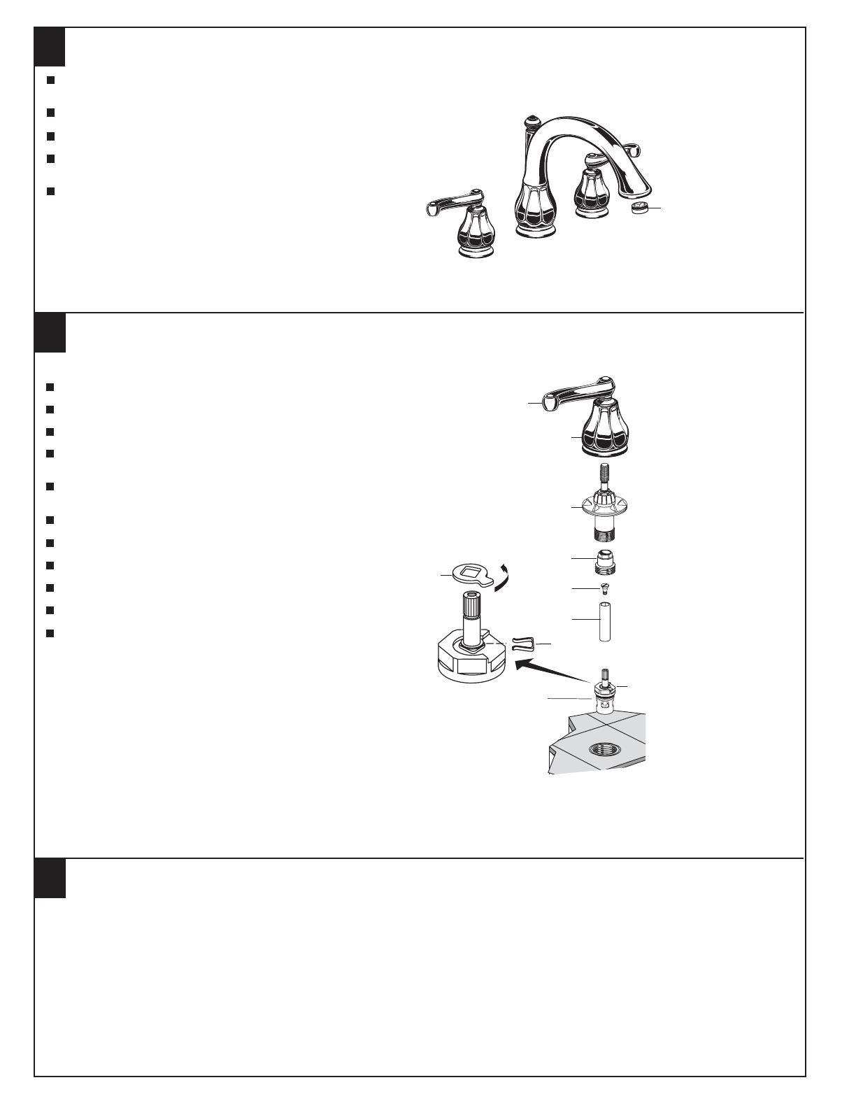
SERVICE
VALVE
CARTRIDGE
Turn off the water supplies
Turn HANDLE (1) to the off position.
Unthread the HANDLE BASE (2) from HANDLE ADAPTER (3).
Unthread HANDLE ADAPTER (3) and remove.
Remove VALVE LOCKNUT (4). A 17mm deep socket
is required.
Remove the CARTRIDGE (5) by pulling up
on the SLEEVE (6).
Remove SCREW (7) and pull off SLEEVE (6).
Remove the SPRING CLIP (8).
Remove the STOP WASHER (9). Turn it 90˚ and replace.
Replace the SPRING CLIP (8).
Reverse the above steps to reassembly the components.
If the spout drips, operate the handles several times from
the off to the on position. Do not force - the handles only turn 90˚.
90
To change the direction of handle rotation
1
3
9
2
4
7
6
8
5
DO: SIMPLY RINSE THE PRODUCT CLEAN WITH CLEAR WATER. DRY WITH A SOFT COTTON
FLANNEL CLOTH.
DO NOT: DO NOT CLEAN THE PRODUCT WITH SOAPS, ACID, POLISH, ABRASIVES, HARSH
CLEANERS, OR A CLOTH WITH A COARSE SURFACE.
CARE INSTRUCTIONS:


