Makita SP6000 User manual

Category
Hand tools supplies
Type
User manual

Makita SP6000 is a plunge cut circular saw with a powerful motor that can deliver up to 5,800 rotations per minute, enabling a maximum cutting depth of 56 millimeters at 90 degrees, 40 millimeters at 45 degrees, and 38 millimeters at 48 degrees. It features double insulation for enhanced safety and can be used for plunge cuts, lengthways and crossways straight cuts, and mitre cuts in wood or aluminum when equipped with a special saw blade.

Makita SP6000 is a plunge cut circular saw with a powerful motor that can deliver up to 5,800 rotations per minute, enabling a maximum cutting depth of 56 millimeters at 90 degrees, 40 millimeters at 45 degrees, and 38 millimeters at 48 degrees. It features double insulation for enhanced safety and can be used for plunge cuts, lengthways and crossways straight cuts, and mitre cuts in wood or aluminum when equipped with a special saw blade.

1
ENGLISH (Original instructions)
INSTRUCTION MANUAL
DOUBLE INSULATION
IMPORTANT: Read Before Using.
Plunge Cut Circular Saw
SP6000
007654
2
ENGLISH (Original instructions)
SPECIFICATIONS
Model SP6000
Blade diameter 165 mm
at 90° 56 mm
at 45° 40 mm
Max. cutting depth
at 48° 38 mm
No load speed (min
-1
) 2,000 - 5,800
Overall length 341 mm
Net weight 4.4 kg
Safety class /II
• Due to our continuing program of research and development, the specifications herein are subject to change without notice.
• Specifications may differ from country to country.
• Weight according to EPTA-Procedure 01/2003
END201-6
Symbols
The following show the symbols used for the equipment.
Be sure that you understand their meaning before use.
󺹮 Read instruction manual.
󺹮 DOUBLE INSULATION
󺹮 Only for EU countries
Do not dispose of electric equipment
together with household waste material!
In observance of European Directive
2012/19/EU on waste electric and
electronic equipment and its
implementation in accordance with
national law, electric equipment that
have reached the end of their life must
be collected separately and returned to
an environmentally compatible
recycling facility.
ENE067-1
Intended use
The tool is specially intended for performing plunge cuts.
In addition, lengthways and crossways straight cuts and
mitre cuts with angles in wood can also be performed
while in firm contact with the workpiece.
If the tool is equipped with the special saw blade for
aluminium, the tool can be used for sawing aluminium.
ENF002-2
Power supply
The tool should be connected only to a power supply of
the same voltage as indicated on the nameplate, and
can only be operated on single-phase AC supply. They
are double-insulated and can, therefore, also be used
from sockets without earth wire.
ENG905-1
Noise
The typical A-weighted noise level determined according
to EN60745:
Sound pressure level (L
pA
) : 81 dB (A)
Sound power level (L
WA
) : 92 dB (A)
Uncertainty (K) : 3 dB (A)
Wear ear protection
ENG900-1
Vibration
The vibration total value (tri-axial vector sum)
determined according to EN60745:
Work mode : cutting wood
Vibration emission (a
h,W
) : 2.5 m/s
2
or less
Uncertainty (K) : 1.5 m/s
2
Work mode : cutting metal
Vibration emission (a
h,M
) : 2.5 m/s
2
or less
Uncertainty (K) : 1.5 m/s
2
ENG901-1
The declared vibration emission value has been
measured in accordance with the standard test
method and may be used for comparing one tool
with another.
The declared vibration emission value may also be
used in a preliminary assessment of exposure.
WARNING:
The vibration emission during actual use of the
power tool can differ from the declared emission
value depending on the ways in which the tool is
used.
Be sure to identify safety measures to protect the
operator that are based on an estimation of
exposure in the actual conditions of use (taking
account of all parts of the operating cycle such as
3
the times when the tool is switched off and when it
is running idle in addition to the trigger time).
ENH101-17
For European countries only
EC Declaration of Conformity
Makita declares that the following Machine(s):
Designation of Machine:
Plunge Cut Circular Saw
Model No./ Type: SP6000
Conforms to the following European Directives:
2006/42/EC
They are manufactured in accordance with the following
standard or standardized documents:
EN60745
The technical file in accordance with 2006/42/EC is
available from:
Makita, Jan-Baptist Vinkstraat 2, 3070, Belgium
31.12.2013
000331
Yasushi Fukaya
Director
Makita, Jan-Baptist Vinkstraat 2, 3070, Belgium
GEA005-3
General Power Tool Safety
Warnings
WARNING Read all safety warnings and all
instructions.
Failure to follow the warnings and instructions
may result in electric shock, fire and/or serious injury.
Save all warnings and
instructions for future reference.
The term "power tool" in the warnings refers to your
mains-operated (corded) power tool or battery-operated
(cordless) power tool.
Work area safety
1. Keep work area clean and well lit. Cluttered or
dark areas invite accidents.
2. Do not operate power tools in explosive
atmospheres, such as in the presence of
flammable liquids, gases or dust. Power tools
create sparks which may ignite the dust or fumes.
3. Keep children and bystanders away while
operating a power tool. Distractions can cause
you to lose control.
Electrical safety
4. Power tool plugs must match the outlet. Never
modify the plug in any way. Do not use any
adapter plugs with earthed (grounded) power
tools. Unmodified plugs and matching outlets will
reduce risk of electric shock.
5. Avoid body contact with earthed or grounded
surfaces such as pipes, radiators, ranges and
refrigerators. There is an increased risk of
electric shock if your body is earthed or grounded.
6. Do not expose power tools to rain or wet
conditions. Water entering a power tool will
increase the risk of electric shock.
7. Do not abuse the cord. Never use the cord for
carrying, pulling or unplugging the power tool.
Keep cord away from heat, oil, sharp edges or
moving parts. Damaged or entangled cords
increase the risk of electric shock.
8. When operating a power tool outdoors, use an
extension cord suitable for outdoor use. Use of
a cord suitable for outdoor use reduces the risk of
electric shock.
9. If operating a power tool in a damp location is
unavoidable, use a residual current device
(RCD) protected supply. Use of an RCD reduces
the risk of electric shock.
10. Use of power supply via a RCD with a rated
residual current of 30mA or less is always
recommended.
Personal safety
11. Stay alert, watch what you are doing and use
common sense when operating a power tool.
Do not use a power tool while you are tired or
under the influence of drugs, alcohol or
medication. A moment of inattention while
operating power tools may result in serious
personal injury.
12. Use personal protective equipment. Always
wear eye protection. Protective equipment such
as dust mask, non-skid safety shoes, hard hat, or
hearing protection used for appropriate conditions
will reduce personal injuries.
13. Prevent unintentional starting. Ensure the
switch is in the off-position before connecting
to power source and/or battery pack, picking
up or carrying the tool. Carrying power tools
with your finger on the switch or energising power
tools that have the switch on invites accidents.
14. Remove any adjusting key or wrench before
turning the power tool on. A wrench or a key left
attached to a rotating part of the power tool may
result in personal injury.
15. Do not overreach. Keep proper footing and
balance at all times. This enables better control
of the power tool in unexpected situations.
4
16. Dress properly. Do not wear loose clothing or
jewellery. Keep your hair, clothing, and gloves
away from moving parts. Loose clothes,
jewellery or long hair can be caught in moving
parts.
17.
If devices are provided for the connection of
dust extraction and collection facilities, ensure
these are connected and properly used.
Use of
dust collection can reduce dust-related hazards.
Power tool use and care
18. Do not force the power tool. Use the correct
power tool for your application. The correct
power tool will do the job better and safer at the
rate for which it was designed.
19. Do not use the power tool if the switch does
not turn it on and off. Any power tool that cannot
be controlled with the switch is dangerous and
must be repaired.
20. Disconnect the plug from the power source
and/or the battery pack from the power tool
before making any adjustments, changing
accessories, or storing power tools. Such
preventive safety measures reduce the risk of
starting the power tool accidentally.
21. Store idle power tools out of the reach of
children and do not allow persons unfamiliar
with the power tool or these instructions to
operate the power tool. Power tools are
dangerous in the hands of untrained users.
22. Maintain power tools. Check for misalignment
or binding of moving parts, breakage of parts
and any other condition that may affect the
power tool’s operation. If damaged, have the
power tool repaired before use. Many accidents
are caused by poorly maintained power tools.
23. Keep cutting tools sharp and clean. Properly
maintained cutting tools with sharp cutting edges
are less likely to bind and are easier to control.
24. Use the power tool, accessories and tool bits
etc. in accordance with these instructions,
taking into account the working conditions
and the work to be performed. Use of the power
tool for operations different from those intended
could result in a hazardous situation.
Service
25. Have your power tool serviced by a qualified
repair person using only identical replacement
parts. This will ensure that the safety of the power
tool is maintained.
26. Follow instruction for lubricating and
changing accessories.
27. Keep handles dry, clean and free from oil and
grease.
GEB031-5
CIRCULAR SAW SAFETY
WARNINGS
Cutting procedures
1.
DANGER: Keep hands away from cutting
area and the blade. Keep your second hand on
auxiliary handle, or motor housing. If both
hands are holding the saw, they cannot be cut by
the blade.
2. Do not reach underneath the workpiece. The
guard cannot protect you from the blade below the
workpiece.
3. Adjust the cutting depth to the thickness of
the workpiece. Less than a full tooth of the blade
teeth should be visible below the workpiece.
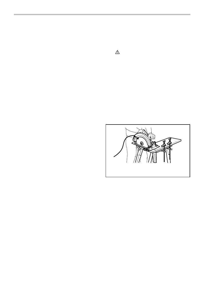
4. Never hold piece being cut in your hands or
across your leg. Secure the workpiece to a
stable platform. It is important to support the
work properly to minimize body exposure, blade
binding, or loss of control.
A typical illustration of proper hand support, workpiece
support, and supply cord routing (if applicable).
000157
5. Hold the power tool by insulated gripping
surfaces only, when performing an operation
where the cutting tool may contact hidden
wiring or its own cord. Contact with a "live" wire
will also make exposed metal parts of the power
tool "live" and could give the operator an electric
shock.
6. When ripping, always use a rip fence or
straight edge guide. This improves the accuracy
of cut and reduces the chance of blade binding.
7.
Always use blades with correct size and shape
(diamond versus round) of arbour holes.
Blades
that do not match the mounting hardware of the saw
will run eccentrically, causing loss of control.
8. Never use damaged or incorrect blade
washers or bolt. The blade washers and bolt
were specially designed for your saw, for optimum
performance and safety of operation.
5
Kickback causes and related warnings
kickback is a sudden reaction to a pinched, bound
or misaligned saw blade, causing an uncontrolled
saw to lift up and out of the workpiece toward the
operator;
when the blade is pinched or bound tightly by the
kerf closing down, the blade stalls and the motor
reaction drives the unit rapidly back toward the
operator;
if the blade becomes twisted or misaligned in the
cut, the teeth at the back edge of the blade can dig
into the top surface of the wood causing the blade
to climb out of the kerf and jump back toward the
operator.
Kickback is the result of saw misuse and/or incorrect
operating procedures or conditions and can be avoided
by taking proper precautions as given below.
9. Maintain a firm grip with both hands on the
saw and position your arms to resist kickback
forces. Position your body to either side of the
blade, but not in line with the blade. Kickback
could cause the saw to jump backwards, but
kickback forces can be controlled by the operator,
if proper precautions are taken.
10. When blade is binding, or when interrupting a
cut for any reason, release the trigger and
hold the saw motionless in the material until
the blade comes to a complete stop. Never
attempt to remove the saw from the work or
pull the saw backward while the blade is in
motion or kickback may occur. Investigate and
take corrective actions to eliminate the cause of
blade binding.
11. When restarting a saw in the workpiece, centre
the saw blade in the kerf and check that saw
teeth are not engaged into the material. If saw
blade is binding, it may walk up or kickback from
the workpiece as the saw is restarted.
12. Support large panels to minimise the risk of
blade pinching and kickback. Large panels tend
to sag under their own weight. Supports must be
placed under the panel on both sides, near the
line of cut and near the edge of the panel.
To avoid kickback, do support
board or panel near the cut.
000154
Do not support board or
panel away from the cut.
000156
13. Do not use dull or damaged blades.
Unsharpened or improperly set blades produce
narrow kerf causing excessive friction, blade
binding and kickback.
14. Blade depth and bevel adjusting locking
levers must be tight and secure before making
cut. If blade adjustment shifts while cutting, it may
cause binding and kickback.
15. Use extra caution when sawing into existing
walls or other blind areas. The protruding blade
may cut objects that can cause kickback.
16. ALWAYS hold the tool firmly with both hands.
NEVER place your hand, leg or any part of
your body under the tool base or behind the
saw, especially when making cross-cuts. If
kickback occurs, the saw could easily jump
backwards over your hand, leading to serious
personal injury.
6
000194
17. Never force the saw. Push the saw forward at a
speed so that the blade cuts without slowing.
Forcing the saw can cause uneven cuts, loss of
accuracy, and possible kickback.
Guard function
18. Check guard for proper closing before each
use. Do not operate the saw if guard does not
move freely and enclose the blade instantly.
Never clamp or tie the guard so that the blade
is exposed. If saw is accidentally dropped, guard
may be bent. Check to make sure that guard
moves freely and does not touch the blade or any
other part, in all angles and depths of cut.
19. Check the operation and condition of the
guard return spring. If the guard and the
spring are not operating properly, they must
be serviced before use. Guard may operate
sluggishly due to damaged parts, gummy deposits,
or a build-up of debris.
20. Assure that the base plate of the saw will not
shift while performing the plunge cut” when
the blade bevel setting is not at 90 󺺨. Blade
shifting sideways will cause binding and likely
kick back.
21. Always observe that the guard is covering the
blade before placing saw down on bench or
floor. An unprotected, coasting blade will cause
the saw to walk backwards, cutting whatever is in
its path. Be aware of the time it takes for the blade
to stop after switch is released.
Additional safety warnings
22. Use extra caution when cutting damp wood,
pressure treated lumber, or wood containing
knots. Maintain smooth advancement of tool
without decrease in blade speed to avoid
overheating the blade tips.
23. Do not attempt to remove cut material when
blade is moving. Wait until blade stops before
grasping cut material.Blades coast after turn off.
24. Avoid cutting nails. Inspect for and remove all
nails from lumber before cutting.
25. Place the wider portion of the saw base on
that part of the workpiece which is solidly
supported, not on the section that will fall off
when the cut is made. As examples, Fig. 1
illustrates the RIGHT way to cut off the end of
a board, and Fig. 2 the WRONG way. If the
workpiece is short or small, clamp it down. DO
NOT TRY TO HOLD SHORT PIECES BY HAND!
Fig. 1
000147
Fig. 2
000150
26. Before setting the tool down after completing
a cut, be sure that the lower guard has closed
and the blade has come to a complete stop.
27. Never attempt to saw with the circular saw
held upside down in a vise. This is extremely
dangerous and can lead to serious accidents.
000029
7
28. Some material contains chemicals which may
be toxic. Take caution to prevent dust
inhalation and skin contact. Follow material
supplier safety data.
29. Do not stop the blades by lateral pressure on
the saw blade.
30. Always use blades recommended in this
manual. Do not use any abrasive wheels.
31. Keep blade sharp and clean. Gum and wood
pitch hardened on blades slows saw and
increases potential for kickback. Keep blade clean
by first removing it from tool, then cleaning it with
gum and pitch remover, hot water or kerosene.
Never use gasoline.
32. Wear a dust mask and hearing protection
when use the tool.
SAVE THESE INSTRUCTIONS.
WARNING:
DO NOT let comfort or familiarity with product
(gained from repeated use) replace strict adherence
to safety rules for the subject product. MISUSE or
failure to follow the safety rules stated in this
instruction manual may cause serious personal
injury.
FUNCTIONAL DESCRIPTION
CAUTION:
Always be sure that the tool is switched off and
unplugged before adjusting or checking function on
the tool.
Adjusting depth of cut
2
1
007656
CAUTION:
After adjusting the depth of cut, always tighten the
clamping screw securely.
Loosen the clamping screw on the depth guide and move the
blade lower limit stopper to the desired depth on the scale plate.
At the desired depth of cut, tighten the clamping screw firmly.
For cleaner, safer cuts, set cut depth so that no more
than one blade tooth projects below workpiece. Using
proper cut depth helps to reduce potential for dangerous
KICKBACKS which can cause personal injury.
NOTE:
Setting the blade lower limit stopper to the desired
depth on the scale plate allows rough depth of cut.
For accurate depth of cut, measure the actual
protrusion of saw blade below the tool base.
Quick stop button for 2 to 3 mm depth of cut
when using guide rail (accessory)
1
007669
This tool has the quick stop button for 2 to 3 mm depth of
cut on the gear housing aside the rear handle when
using guide rail. This is used when avoiding splinter on
the workpiece in the cut. Make a pass of the 2 to 3 mm
first cut and then make another pass of usual cut.
To o bt a in t he 2 t o 3 m m d epth o f cut , p us h i n the s to p
button toward the saw blade. This is convenient for
avoiding splinter on the workpiece.
1. Quick stop
button
1. Clamping screw
2.
Blade lower limit
stopper
8
To re l e as e th e dept h of cu t fr o m this po si tio n f or f re e
depth of cut, just pull the button back.
1
007670
Bevel cutting
1
1
2
007657
Tilting to the right
1
007659
Turn the positive stopper so that the arrow on it points
one of two positions (vertical for 22.5°, horizontal for 45°).
Loosen the clamping screws in front and back. Then, tilt
the tool base until it stops and secure the base with the
clamping screws.
To g et 4 8° b ev el a ng l e, m ov e t he l ev e r t o 4 8° m ar ki n g a s
far as it will go. Turn the positive stopper so that the
arrow on it points to the horizontal position. Then, tilt the
tool base until it stops and secure the base with the
clamping screws.
1
007660
Tilting to the left
1
007661
The tool can be tilted to the left bevel angle. To get
the left bevel angle, loosen the clamping screws in
front and back, tilt the tool handle slightly to the right and
push two bevel angle shifting levers at the same time in
the direction of arrow which has a marking -1. And then
tilt the tool handle to the left while pushing these two
levers at the same time. Secure the base with the
clamping screws.
NOTE:
Returning the blade to the right angle makes the
shifting lever return to 0° by itself.
Sighting
1
2
A
B
007671
When using the tool without guide rail (accessory)
For straight cuts, align the A position on the front of the
base with your cutting line. For 45° bevel cuts, align the
B position with it.
When using the tool with guide rail (accessory)
For both straight cuts and 45° bevel cuts, always align
the A position on the front of the base with your cutting
line.
Switch action
1
2
007664
1. Lock-off button
2. Switch trigger
1. Base
2. Cutting line
1. Bevel angle
shifting lever
1. Lever
1. Positive stopper
1. Clamping
screws
2. Tool base
1. Quick stop
button
9
CAUTION:
Before plugging in the tool, always check to see
that the switch trigger actuates properly and
returns to the "OFF" position when released.
To p re ven t t he s wi tc h t ri gg er f ro m b ei n g ac ci de nta ll y
pulled, a lock-off button is provided. To start the tool,
push in the lock-off button and pull the switch trigger.
Release the switch trigger to stop.
Speed adjusting dial
1
007663
The tool speed can be adjusted by turning the adjusting
dial. Higher speed is obtained when the dial is turned in
the direction of number 6; lower speed is obtained when
it is turned in the direction of number 1.
Refer to the table to select the proper speed for the
workpiece to be cut. However, the appropriate speed
may differ with the type or thickness of the workpiece. In
general, higher speeds will allow you to cut workpieces
faster but the service life of the blade will be reduced.
Number min
-1
1
2
3
4
5
6
2,000
2,500
3,500
4,500
5,500
5,800
014599
CAUTION:
The speed adjusting dial can be turned only as far
as 6 and back to 1. Do not force it past 6 or 1, or
the speed adjusting function may no longer work.
The speed adjusting dial is not for using low speed
rated saw blades but for obtaining a speed which is
suitable to material of workpiece. Use only saw
blades which are rated for at least the maximum no
load speed stated in the SPECIFICATIONS.
The tools equipped with electronic function are easy to
operate because of the following features.
Overload protector
When the tool is overloaded and current flows above a
certain level, the tool automatically stops to protect motor.
Constant speed control
Electronic speed control for obtaining constant speed.
Possible to get fine finish, because the rotating speed is
kept constant even under load condition.
Soft start feature
Soft start because of suppressed starting shock.
ASSEMBLY
CAUTION:
Always be sure that the tool is switched off and
unplugged before carrying out any work on the tool.
Hex wrench storage
1
007684
Hex wrench is stored on the tool. To remove hex wrench,
just pull it out.
To in s ta l l he x wr en ch , pl ace i t o n t h e gri p an d in s e r t it a s
far as it will go.
Removing or installing saw blade
CAUTION:
Do not use saw blades which do not comply with
the characteristics specified in these instructions.
Use only saw blades which are rated for at least
the maximum no load speed stated in the
SPECIFICATIONS.
Be sure the blade is installed with teeth pointing up
at the front of the tool.
Use only the Makita wrench to install or remove the
blade.
To r em ove t he b lad e, pus h in t h e l oc k - of f b ut t on t o
unlock the upper limit stopper.
2
1
007662
Turn the locking lever to lock the saw head for replacing
a blade.
1. Lock-off button
2. Locking lever
1. Hex wrench
1. Speed adjusting
dial
10
1
007655
With the lock-off button depressed and the locking lever
turned, lower the handle so that the lock pin fits in the groove
formed by the locking lever and the depth guide with scale
plate. Make sure that the lock pin fits in the groove.
Press the shaft lock fully so that the blade cannot revolve and
use the wrench to loosen the hex bolt counterclockwise. Then
remove the hex bolt, outer flange and blade.
1
2
007658
To i ns tal l t h e b la d e , f ol lo w t he r em ova l p r o c e d ur e i n
reverse. BE SURE TO TIGHTEN THE HEX BOLT
CLOCKWISE SECURELY.
1
2
3
4
007672
Connecting a vacuum cleaner
1
2
007673
When you wish to perform clean cutting operation,
connect a Makita vacuum cleaner to your tool. Connect
a hose of the vacuum cleaner to the dust port as shown
in the figure.
OPERATION
Section cutting (ordinary sawing)
CAUTION:
Be sure to move the tool forward in a straight line
gently. Forcing or twisting the tool will result in
overheating the motor and dangerous kickback,
possibly causing severe injury.
Never approach any part of your body under the
tool base when section cutting, especially at
starting. Doing so may cause serious personal
injuries. The blade is exposed under the tool base.
Hold the tool firmly. The tool is provided with both a front
grip and rear handle. Use both to best grasp the tool. If
both hands are holding saw, they cannot be cut by the
blade. Set the front of base on the workpiece to be cut
without the blade making any contact. Then push in the
lock-off button and turn the tool on and wait until the
blade attains full speed. Now press down the saw head
slowly to the preset depth of cut and simply move the
tool forward over the workpiece surface, keeping it flat
and advancing smoothly until the sawing is completed.
To g et c le an c ut s , k ee p y o u r s awin g l in e s tr a i ght a n d
your speed of advance uniform. If the cut fails to properly
follow your intended cut line, do not attempt to turn or
force the tool back to the cut line. Doing so may bind the
blade and lead to dangerous kickback and possible
serious injury. Release switch, wait for blade to stop and
then withdraw tool. Realign tool on new cut line, and
start cut again. Attempt to avoid positioning which
exposes operator to chips and wood dust being ejected
from saw. Use eye protection to help avoid injury.
007674
1. Vacuum cleaner
2. Dust port
1. Hex bolt
2. Outer flange
3. Saw blade
4. Inner flange
1. Hex wrench
2. Shaft lock
1. Locking lever
11
When using with guide rail (accessory)
1
007685
Place the tool on the rear end of guide rail. Turn two
adjusting screws on the tool base so that the tool slides
smoothly without a clatter. Hold the tool firmly. The tool is
provided with both a front grip and rear handle. Use both
to best grasp the tool. Turn on the tool, press down the
tool to the preset depth of cut and cut the splinterguard
along the full length with a stroke. The edge of the
splinterguard corresponds to the cutting edge.
When bevel cutting with the guide rail, slide the slide
lever on the tool base so that the tool does not fall down
on its side.
1
007666
Move the slide lever on the tool base in the direction of
arrow so that it engages the undercut groove in the
guide rail.
Rip fence (guide rule) (Accessory)
1
007675
The handy rip fence allows you to do extra-accurate
straight cuts. Simply slide the rip fence up snugly against
the side of the workpiece and secure it in position with
the screws on the front and the back of the base. It also
makes repeated cuts of uniform width possible.
Overturning the rip fence (guide rule) also works as a
sub base for the tool.
Plunge cutting (Cutting-out)
1
2
007686
WARNING:
To a vo i d a k i c k ba c k , b e su re to ob se rve t he
following instructions.
When using the tool without guide rail
Place the tool on the workpiece with the rear edge of tool
base against a fixed stop or equivalent which is devised
by an operator.
When using the tool with guide rail
Place the tool on the guide rail with the rear edge of tool
base against a fixed stop or equivalent which is clamped
on the guide rail.
Hold the tool firmly with one hand on the front grip and
the other on the tool handle. Then push in the lock-off
button and turn the tool on and wait until the blade
attains full speed. Now press down the saw head slowly
to the preset depth of cut and simply move the tool
forward to the desired plunge position.
NOTE:
The markings on the side of the blade guard show
the absolute front and the absolute rear cutting
points of the saw blade (A for diameter 160 mm
and B for diameter 165 mm) at the maximum
cutting depth and using the guide rail.
B
A
A
B
007678
Guide device (accessories)
Use of the miter gauge (accessory) allows exact miter
cuts with angles and fitting works.
Use of the clamp (accessory) ensures firm hold of
workpiece on the table.
1. Rear edge of
tool base
2. Fixed stop
1. Rip fence
(Guide rule)
1. Slide lever
1.
Adjusting screws
12
MAINTENANCE
CAUTION:
Always be sure that the tool is switched off and
unplugged before attempting to perform inspection
or maintenance.
Never use gasoline, benzine, thinner, alcohol or the
like. Discoloration, deformation or cracks may result.
Adjusting for accuracy of 90° and 4 cut
(vertical and 45° cut)
This adjustment has been made at the factory. But if it is
off, adjust the adjusting screws with a hex wrench while
inspecting 90° or 45° the blade with the base using a
triangular rule or square rule, etc.
1
007667
1
007668
NOTE:
Adjusting for accuracy of 22.5° , 48° and -1° cut
cannot be performed.
Replacing carbon brushes
1
001145
Remove and check the carbon brushes regularly.
Replace when they wear down to the limit mark. Keep
the carbon brushes clean and free to slip in the holders.
Both carbon brushes should be replaced at the same
time. Use only identical carbon brushes.
1
2
007676
Use a screwdriver to remove the brush holder caps.
Take o ut t h e w or n c ar bo n b ru s hes , i nsert t h e n ew o ne s
and secure the brush holder caps.
To ma i n tai n pr od uc t SA FE TY an d RE LI ABI LI TY, re pa ir s,
any other maintenance or adjustment should be
performed by Makita Authorized Service Centers,
always using Makita replacement parts.
OPTIONAL ACCESSORIES
CAUTION:
These accessories or attachments are
recommended for use with your Makita tool
specified in this manual. The use of any other
accessories or attachments might present a risk of
injury to persons. Only use accessory or
attachment for its stated purpose.
If you need any assistance for more details regarding
these accessories, ask your local Makita Service Center.
Saw blades
Guide rail
Rip fence (Guide rule)
Miter gauge
Clamp
Hex wrench
Sheet set for guide rail
Rubber sheet set for guide rail
Position sheet set for guide rail
NOTE:
Some items in the list may be included in the tool
package as standard accessories. They may differ
from country to country.
1. Screwdriver
2. Brush holder
cap
1. Limit mark
1. Adjusting screw
for 45 󺺨
1. Adjusting screw
for 90 󺺨
13
14
15
16
www.makita.com
Makita Jan-Baptist Vinkstraat 2, 3070, Belgium
Makita Corporation Anjo, Aichi, Japan
884683J228
1 / 1

Makita SP6000 User manual

Category
Hand tools supplies
Type
User manual

Makita SP6000 is a plunge cut circular saw with a powerful motor that can deliver up to 5,800 rotations per minute, enabling a maximum cutting depth of 56 millimeters at 90 degrees, 40 millimeters at 45 degrees, and 38 millimeters at 48 degrees. It features double insulation for enhanced safety and can be used for plunge cuts, lengthways and crossways straight cuts, and mitre cuts in wood or aluminum when equipped with a special saw blade.

Ask a question and I''ll find the answer in the document

Finding information in a document is now easier with AI

Ask the document