
For Customer Use:
Enter below the Model No. and Serial
No. which are located either on the rear,
bottom or side of the cabinet. Retain this
information for future reference.
Model No.
Serial No.
LVT0382-001A
[J]
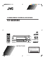
RX-6500VBK
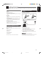
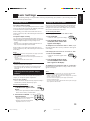
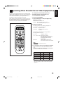
INSTRUCTIONS
AUDIO/VIDEO CONTROL RECEIVER
RX-6500V AUDIO/VIDEO CONTROL RECEIVER
STANDBY
PHONES
SPEAKERS
12
ADJUST
SETTING
MEMORY
DVD
CD
TV SOUND/DBS
TAPE/MD
VCR
PHONO
THEATER LIVE CLUB DANCE CLUB HALL PAVILLION
DIGITAL AUTO
SOURCE NAME
SOURCE NAME
ONE TOUCH OPERATION/
INPUT ATT.
DSP. MODE MULTI CURSOR
ANALOG/DIGITAL
SURROUND
FM/AM
MASTER VOLUME
–+
— OFF_ ON
POWER
DIGITAL
ON
CATV CH
VCR CH
RM-SRX6500J REMOTE CONTROL
POWER
TV SOUND/ DBS
TV
SURROUND
SURROUND
MODE
CD - DISC
SOUND
VCR
VCR
AUDIO
CATV
CONTROL
CD
PHONO
SLEEP
CATV/ SAT
DVD
TAPE/MD FM/AM
ANALOG/DIGITAL
TEST
100+
EFFECT
TV/ VIDEO
MUTING
REC PAUSE
1
2
3
4
5
6
7
/P
8
9
0
10
+10
CNTR
REAR•L
REAR•R
SUBWOOFER
MENU
TV CH TV VOL VOLUME
ENTER
8
7
3
RETURN
DIGITAL
RX-6500V[J]COVER/1 99.12.10, 6:15 PM1

RX-6000VBK/RX-6008VBK[J]/
RX-6500VBK[J]
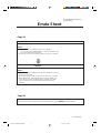
Errata Sheet
Please notice the following modifications when reading Instructions.
Page 18.
Incorrect
Notes:
• If “REAR SPK” and “CENTER SPK” are set to “NONE,”
— you can select only “HEAD PHONE” or “OFF” for the DSP mode.
— you cannot select Surround mode.
• No sounds come out of the center speaker, even if it is connected.
Correct
Notes:
• If “REAR SPK” and “CENTER SPK” are set to “NONE,” you cannot
select Surround mode.
• No sounds come out of the center speaker, even if it is connected.
• When “REAR SPK” and “CENTER SPK” are set to “NONE,” the
same effect as used for the 3D-PHONIC is applied to any DAP
mode to maintain the surround elements with only two front
speakers.
Page 20.
On page 20, in the DSP mode cycle it is written that "3D ACTION" will be selected after "HEAD PHONE,"
but the order has been changed so that "3D ACTION" will be selected before "HEAD PHONE."
LV 41818-001A
Errata for RX-6000/6008/6500[J] 99.12.27, 7:09 PM1

G-1
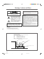
Warnings, Cautions and Others
Floor
Spacing 15 cm or more
Stand height 15 cm or more
Wall or obstructions
Front
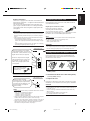
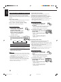
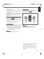
Caution: Proper Ventilation
To avoide risk of electric shock and fire and to protect from damage.
Locate the apparatus as follows:
Front: No obstructions open spacing.
Sides: No obstructions in 10 cm from the sides.
Top: No obstructions in 10 cm from the top.
Back: No obstructions in 15 cm from the back
Bottom: Place on the level surface.
In addition, maintain the best possible air circulation as illustrated.
CAUTION: TO REDUCE THE RISK OF ELECTRIC SHOCK.
DO NOT REMOVE COVER (OR BACK)
NO USER SERVICEABLE PARTS INSIDE.
REFER SERVICING TO QUALIFIED SERVICE PERSONNEL.
RISK OF ELECTRIC SHOCK
DO NOT OPEN
The lightning flash with arrowhead symbol,
within an equilateral triangle is intended to
alert the user to the presence of uninsulated
"dangerous voltage" within the product's
enclosure that may be of sufficient
magnitude to constitute a risk of electric
shock to persons.
The exclamation point within an equilateral
triangle is intended to alert the user to the
presence of important operating and
maintenance (servicing) instructions in the
literature accompanying the appliance.
CAUTION
WARNING: TO REDUCE THE RISK OF FIRE
OR ELECTRIC SHOCK, DO NOT EXPOSE
THIS APPLIANCE TO RAIN OR MOISTURE.
CAUTION
To reduce the risk of electrical shocks, fire, etc.:
1. Do not remove screws, covers or cabinet.
2. Do not expose this appliance to rain or moisture.
Caution –– POWER switch!
Disconnect the mains plug to shut the power off completely. The
POWER switch in any position does not disconnect the mains line.
The power can be remote controlled.
For U.S.A.
This equipment has been tested and found to comply with the limits
for a Class B digital device, pursuant to part 15 of the FCC Rules.
These limits are designed to provide reasonable protection against
harmful interference in a residential installation.
This equipment generates, uses and can radiate radio frequency
energy and, if not installed and used in accordance with the
instructions, may cause harmful interference to radio
communications. However, there is no guarantee that interference
will not occur in a particular installation. If this equipment does cause
harmful interference to radio or television reception, which can be
determined by turning the equipment off and on, the user is
encouraged to try to correct the interference by one or more of the
following measures:
Reorient or relocate the receiving antenna.
Increase the separation between the equipment and receiver.
Connect the equipment into an outlet on a circuit different from that
to which the receiver is connected.
Consult the dealer or an experienced radio/TV technician for help.
RX-6500V
RX-6500V[J]Safety/1 99.12.10, 6:14 PM1

1
English
Table of Contents
Using the DSP Modes ................................ 18
Available DSP Modes According to the Speaker Arrangement .. 20
Adjusting the 3D-PHONIC Modes .......................................... 21
Adjusting the DAP Modes and Headphones mode .................. 21
Adjusting the Surround Modes ................................................ 22
Activating the DSP Modes ....................................................... 25
COMPU LINK Remote Control System ......... 26
AV COMPU LINK Remote Control System .... 27
Operating JVC’s Audio/Video Components ... 29
Operating Other Manufacturers’ Video
Equipment ................................................ 31
Troubleshooting......................................... 33
Specifications............................................ 34
Parts Identification...................................... 2
Getting Started........................................... 3
Before Installation ...................................................................... 3
Checking the Supplied Accessories ........................................... 3
Connecting the FM and AM Antennas ....................................... 3
Connecting the Speakers ............................................................ 4
Connecting Audio/Video Components....................................... 5
Connecting the Power Cord ....................................................... 7
Putting Batteries in the Remote Control .................................... 7
Basic Operations ......................................... 8
Turning the Power On and Off (Standby) .................................. 8
Selecting the Source to Play....................................................... 8
Adjusting the Volume ................................................................. 9
Selecting the Front Speakers ...................................................... 9
Muting the Sound ....................................................................... 9
Adjusting the Subwoofer Output Level.................................... 10
Attenuating the Input Signal .................................................... 10
Reinforcing the Bass ................................................................ 10
Adjusting the Tone ................................................................... 10
Basic Settings........................................... 11
Recording a Source .................................................................. 11
Adjusting the Front Speaker Output Balance........................... 11
Changing the Source Name...................................................... 11
Setting the Speakers for the DSP Modes ................................. 12
Digital Input (DIGITAL IN) Terminal Setting ......................... 14
Selecting the Analog or Digital Input Mode ............................ 14
Storing the Basic Settings and Adjustments
— One Touch Operation .................................................... 15
Using the Sleep Timer .............................................................. 15
Receiving Radio Broadcasts ........................ 16
Tuning in Stations Manually .................................................... 16
Using Preset Tuning ................................................................. 16
Selecting the FM Reception Mode........................................... 17
EN01-07.RX-6500V[J] 99.12.16, 1:16 PM1

2
English
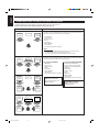
Parts Identification
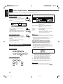
Become familiar with the buttons and controls on the receiver before use.
Refer to the pages in parentheses for details.
Front Panel
~
POWER button and STANDBY lamp (8)
Ÿ
SOURCE NAME (TV SOUND/DBS) button
(11)
!
Display (8)
⁄
ONE TOUCH OPERATION/INPUT ATT.
button (15)
@
DSP MODE button (21)
¤
SURROUND button and lamp (25)
#
Remote sensor (7)
‹
ADJUST button (10) *
$
SETTING button (12 – 14) *
›
MASTER VOLUME control (9)
%
MEMORY button (16)
fi
MULTI CURSOR buttons
^
ANALOG/DIGITAL button and DIGITAL
AUTO lamp (14)
fl
Source selecting buttons (8)
DVD, TV SOUND/DBS, VCR, CD, TAPE/MD,
PHONO, FM/AM *
&
SOURCE NAME (TAPE/MD) button
(8, 11, 14)
‡
SPEAKERS 1/2 buttons (9)
*
PHONES jack (9)
CATV CH VCR CH
100+RETURN
5
6
7
/P
8
R/M-SRX6500J REMOTE CONTROL
TV SOUND/ DBS
TV
SURROUND
SURROUND
MODE
CD - DISC
SOUND
CATV
CONTROL
VCR
VCR
AUDIO
CD
PHONO
SLEEP
CATV/SAT
DVD
TAPE/MD FM/AM
ANALOG/DIGITAL
TESTEFFECT
TV/ VIDEO
MUTING
REC PAUSE
1
2
3
4
9
0
10
+10
CNTR
REAR•L
REAR•R
SUBWOOFER
MENU
TV CH TV VOL VOLUME
ENTER
8
7
3
~
Ÿ
!
⁄
@
¤
#
‹
$
›
%
^
fl
fi
&
‡
°
(
POWER
*
ON
RX-6500V AUDIO/VIDEO CONTROL RECEIVER
STANDBY
PHONES
SPEAKERS
12
ADJUST
SETTING
MEMORY
DVD
CD TAPE/MD
VCR
PHONO
THEATER LIVE CLUB DANCE CLUB HALL PAVILLION
DIGITAL AUTO
SOURCE NAME
SOURCE NAME
ONE TOUCH OPERATION/
INPUT ATT.
DSP. MODE MULTI CURSOR
ANALOG/DIGITAL
SURROUND
FM/AM
MASTER VOLUME
–+
— OFF_ ON
POWER
DIGITAL
Ÿ
!
⁄ @#‹$›
%
fi
*
‡
&
fl
~
¤
^
TV SOUND/DBS
IMPORTANT:
To use the MULTI CURSOR buttons (w) on the front panel:
What these buttons actually do depends on which function you are trying to adjust. Before using these buttons, select the function by
pressing one of the buttons marked with *.
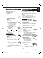
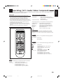
Remote Control
~
POWER buttons (8, 30)
CATV/SAT, TV, VCR, AUDIO
Ÿ
Source selecting buttons (8)
DVD, TV SOUND/DBS, VCR, CD, PHONO,
TAPE/MD, FM/AM
!
Operating buttons for audio/video components
(29, 30)
⁄
REC PAUSE button (30)
@
SURROUND button (25)
¤
CATV CH +/– buttons (31)
#
SURROUND MODE button (21)
‹
• 10 keys for selecting preset channel (17)
• 10 keys for adjusting sound (22 – 24, 29)
• 10 keys for operating audio/video components
(29, 30)
$
TV/VIDEO button (30)
›
MUTING button (9)
%
TV CH +/– buttons (30)
fi
SLEEP button (15)
^
ANALOG/DIGITAL button (14)
fl
CATV CONTROL (31)
&
SOUND button (21)
‡
VCR CH +/– buttons (30)
*
CD-DISC button (29)
°
VOLUME +/– buttons (9)
(
TV VOL +/– buttons (30)
EN01-07.RX-6500V[J] 99.12.16, 1:16 PM2

3
English
ANTENNA
AM
LOOP
AM
EXT
AM
EXT
AM
LOOP
FM 75
COAXIAL
AM
LOOP
ANTENNA
AM
EXT
FM 75
COAXIAL
FM 75
COAXIAL
ANTENNA
Getting Started
This section explains how to connect audio/video components and speakers to the receiver, and how to connect the
power supply.
Before Installation
General
• Be sure your hands are dry.
• Turn the power off to all components.
• Read the manuals supplied with the components you are going to
connect.
Locations
• Install the receiver in a location that is level and protected from
moisture.
• The temperature around the receiver must be between –5˚C and
35˚C (23˚F and 95˚F).
• Make sure there is good ventilation around the receiver. Poor
ventilation could cause overheating and damage the receiver.
Handling the receiver
• Do not insert any metal object into the receiver.
• Do not disassemble the receiver or remove screws, covers, or
cabinet.
• Do not expose the receiver to rain or moisture.
Checking the Supplied Accessories
Check to be sure you have all of the following items, which are
supplied with the receiver.
The number in the parentheses indicates the quantity of the pieces
supplied.
• Remote Control (1)
• Batteries (2)
• AM Loop Antenna (1)
• FM Antenna (1)
If anything is missing, contact your dealer immediately.
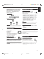
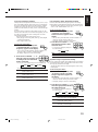
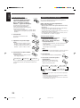
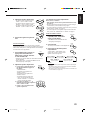
A. Using a Supplied FM Antenna
The FM antenna provided can be connected to the FM 75Ω
COAXIAL terminal as temporary measure.
B. Using a Standard Type Connector (Not Supplied)
A standard type connector should be connected to the FM 75Ω
COAXIAL terminal.
Note:
If reception is poor, connect an outdoor antenna.
Before attaching a 75
Ω
coaxial cable (the kind with a round wire going
to an outdoor antenna), disconnect the supplied FM antenna.
Connecting the FM and AM
Antennas
FM Antenna Connections
B
A
Extend the supplied FM antenna horizontally.
Outdoor FM Antenna Cable
FM Antenna
EN01-07.RX-6500V[J] 99.12.16, 1:16 PM3

4
English
+
+
–
2
1
2
1
–
FRONT SPEAKERS
LEFTRIGHT
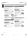
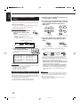
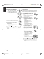
Basic connecting procedure
1 Cut, twist and remove the insulation at the end of
each speaker signal cable (not supplied).
2 Turn the knob counterclockwise.
3 Insert the speaker signal cable.
4 Turn the knob clockwise.
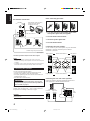
Connecting the front speakers
You can connect two pairs of front speakers (one pair to the FRONT
SPEAKERS 1 terminals, and another pair to the FRONT
SPEAKERS 2 terminals).
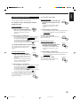
ANTENNA
AM
EXT
AM
LOOP
FM 75
COAXIAL
2
3
1
Snap the tabs on the loop frame
into the slots of the base to
assemble the AM loop.
Turn the loop antenna until you have the best reception.
Notes:
• Make sure the antenna conductors do not touch any other
terminals, connecting cords and power cord. This could cause poor
reception.
• If reception is poor, connect an outdoor single vinyl-covered wire to
the AM EXT terminal. (Keep the AM loop antenna connected.)
Connecting the Speakers
You can connect the following speakers:
• Two pairs of front speakers to produce normal stereo sound.
• One pair of rear speakers to enjoy the surround effect.
• One center speaker to produce more effective surround effect (to
emphasize human voices).
• One subwoofer to enhance the bass.
IMPORTANT:
After connecting the speakers listed above, set the speaker
setting information properly to obtain the best possible DSP
effect. For details, see page 12.
For each speaker (except for a subwoofer), connect the (–) and (+)
terminals on the rear panel to the (–) and (+) terminals marked on
the speakers. For connecting a subwoofer, see page 5.
1
CAUTION:
Use speakers with the SPEAKER IMPEDANCE indicated by the
speaker terminals.
AM Antenna Connections
2
Outdoor single vinyl-covered wire
AM Loop Antenna
(not supplied)
RIGHT
1
RIGHT
1
RIGHT
1
34
FRONT SPEAKERS 1 Left speakerRight speaker
FRONT SPEAKERS 2
Left speakerRight speaker
RIGHT LEFT
CENTER
SPEAKER
REAR
SPEAKERS
Connecting the rear and center speakers
Connect rear speakers to the REAR SPEAKERS terminals and a
center speaker to the CENTER SPEAKER terminals.
Right rear
speaker
Left rear
speaker
Center speaker
EN01-07.RX-6500V[J] 99.12.16, 1:17 PM4

5
English
Connecting the subwoofer speaker
You can enhance the bass by connecting a subwoofer.
Connect the input jack of a powered subwoofer to the
SUBWOOFER OUT jack on the rear panel, using a cable with RCA
pin plugs (not supplied).
SUBWOOFER
OUT
Powered subwoofer
Connecting Audio/Video Components
You can connect the following audio/video components to this
receiver. Refer also to the manuals supplied with your components.
Audio Components Video Components
• CD player* • DVD player*
• Turntable • TV
• Cassette deck • DBS tuner*
or MD recorder* • VCR
*
You can connect these components using the methods described
in “Analog connections” (below) or in “Digital connections” (see
page 7).
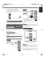
Analog connections
Audio component connections
Use the cables with RCA pin plugs (not supplied).
Connect the white plug to the audio left jack, and the red plug to the
audio right jack.
CAUTION:
If you connect a sound-enhancing device such as a graphic equalizer
between the source components and this receiver, the sound output
through this receiver may be distorted.
RIGHT LEFT
AUDIO
VCR
IN
(PLAY)
OUT
(REC)
CD
PHONO
TV SOUND
/DBS
TAPE
/MD
IN
(PLAY)
OUT
(REC)
CD player
To audio output
CD player
RIGHT LEFT
AUDIO
VCR
IN
(PLAY)
OUT
(REC)
CD
PHONO
TV SOUND
/DBS
TAPE
/MD
IN
(PLAY)
OUT
(REC)
ANTENNA
AM
EXT
AM
LOOP
FM 75
COAXIAL
Turntable
Turntable
To audio
output
If an earth cable is provided for
your turntable, connect the cable
to the terminal marked (H) of the
ANTENNA terminals on the rear
panel.
Note:
Any turntables incorporating a small-output cartridge such as an MC
(moving-coil type) must be connected to this receiver through a
commercial head amplifier or step-up transformer. Direct connection
may result in insufficient volume.
RIGHT LEFT
AUDIO
VCR
IN
(PLAY)
OUT
(REC)
CD
PHONO
TV SOUND
/DBS
TAPE
/MD
IN
(PLAY)
OUT
(REC)
Cassette deck or MD recorder
Cassette deck
To audio outputTo audio input
MD recorder
Note:
You can connect either a cassette deck or an MD recorder to the
TAPE/MD jacks. When connecting an MD recorder to the TAPE/MD
jacks, change the source name, which will be shown on the display
when selected as the source, to “M D.” See page 11 for details.
If your audio components have a COMPU LINK-3 terminal
See also page 26 for detailed information about the connection and
the COMPU LINK-3 remote control system.
To audio input
To audio output
EN01-07.RX-6500V[J] 99.12.16, 1:17 PM5

6
English
RIGHT
RIGHT LEFT
AUDIO
VCR
IN
(PLAY)
OUT
(REC)
CD
PHONO
TV SOUND
/DBS
TAPE
/MD
IN
(PLAY)
OUT
(REC)
VIDEO
VIDEO
S-VIDEO
MONITOR
OUT
VCR
IN
(PLAY)
OUT
(REC)
DBS
DVD
RIGHT
LEFT
AUDIO
DVD
DIGITAL OUT
PCM / DOLBY DIGITAL
/ DTS
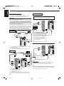
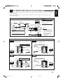
Video component connections
Use the cables with RCA pin plugs (not supplied).
Connect the white plug to the audio left jack, the red plug to the
audio right jack, and the yellow plug to the video jack.
Note:
When connecting the DBS tuner to the TV SOUND/DBS jacks,
change the source name, which will be shown on the display when
selected as the source, to “DBS.” See page 11 for details.
If your audio components have an AV COMPU LINK terminal
See also page 27 for detailed information about the connection and
the AV COMPU LINK remote control system.
DBS
RIGHT LEFT
AUDIO
VCR
IN
(PLAY)
OUT
(REC)
CD
PHONO
TV SOUND
/DBS
TAPE
/MD
IN
(PLAY)
OUT
(REC)
VIDEO
VIDEO
S-VIDEO
MONITOR
OUT
VCR
IN
(PLAY)
OUT
(REC)
DBS
DVD
RIGHT
LEFT
AUDIO
DVD
DIGITAL OUT
PCM / DOLBY DIGITAL
/ DTS
To composite video output
DBS tuner
To audio
output
To composite video input
Connect the TV to the MONITOR
OUT jack to view the playback
picture from the other connected
video components.
To audio
output
To S-video input (for better
playback picture quality)
TV
When connecting the TV to the TV SOUND/DBS jacks, DO NOT
connect the TV’s video output to the video input terminal.
RIGHT LEFT
AUDIO
VCR
IN
(PLAY)
OUT
(REC)
CD
PHONO
TV SOUND
/DBS
TAPE
/MD
IN
(PLAY)
OUT
(REC)
DIGITAL 2 (CD)
DIGITAL 1
(DVD)
DIGITAL 3(DBS)
PCM / DOLBY DIGITAL
/ DTS
DIGITAL IN
VIDEO
VIDEO
S-VIDEO
MONITOR
OUT
VCR
IN
(PLAY)
OUT
(REC)
DBS
DVD
RIGHT
LEFT
AUDIO
DVD
A
B
DF
DIGITAL OUT
PCM / DOLBY DIGITAL
/ DTS
C
E
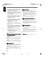
VCR
Å To left/right channel audio output
ı To left/right channel audio input
Ç To composite video output
Î To composite video input
‰ To S-video output (for better playback picture quality)
Ï To S-video input (for better picture recording quality)
VCR
Å To front left/right channel audio output (or to audio mixed
output if necessary)
ı To composite video output
Ç To S-video output (for better playback picture quality)
TV and/or DBS tuner
DVD player
DVD
A
C
VIDEO
VIDEO
S-VIDEO
MONITOR
OUT
VCR
IN
(PLAY)
OUT
(REC)
DBS
DVD
RIGHT
LEFT
AUDIO
DVD
B
DVD player
IMPORTANT:
This receiver is equipped with both the composite video and S-video input
terminals for connecting video components.
You do not have to connect both the composite video and S-video terminals.
However, remember that the video signals from the composite video
input terminal are output only through the composite video output
terminals, while the ones from the S-video input terminal are output
only through the S-video output terminal.
Therefore, if a recording video component and a playing video component
are connected to the receiver through the different video terminals, you
cannot record the picture from the playing component on the recording
component. In addition, if the TV and a playing video component are
connected to the receiver through the different video terminals, you cannot
view the playback picture from the playing component on the TV.
EN01-07.RX-6500V[J] 99.12.16, 1:17 PM6

7
English
Digital connections
This receiver is equipped with one DIGITAL OUT terminal and
three DIGITAL IN terminals — one digital coaxial terminal and two
digital optical terminal.
You can connect any digital equipment such as DBS tuner, DVD
player, CD player, and MD recorder to one of the digital terminals
using a digital coaxial cable (not supplied) or digital optical cable
(not supplied).
IMPORTANT:
• When connecting the DVD player or the DBS tuner using the digital
terminal, you also need to connect it to the video jack on the rear.
Without connecting it to the video jack, you can view no playback
picture.
• After connecting the components using the DIGITAL IN terminals,
set the following correctly if necessary.
– Set the digital input (DIGITAL IN) terminal setting correctly. For
details, see “Digital Input (DIGITAL IN) Terminal Setting” on page
14.
– Select the digital input mode correctly. For details, see “Selecting
the Analog or Digital Input Mode” on page 14.
Connecting the Power Cord
Before plugging the receiver into an AC outlet, make sure that all
connections have been made.
Plug the power cord into an AC outlet.
Keep the power cord away from the
connecting cables and the antenna. The
power cord may cause noise or screen
interference. We recommend that you use a coaxial cable to connect
the antenna, since it is well-shielded against interference.
Note:
The preset settings such as preset channels and sound adjustment
may be erased in a few days in the following cases:
– When you unplug the power cord.
– When a power failure occurs.
CAUTIONS:
• Do not touch the power cord with wet hands.
• Do not pull on the power cord to unplug the cord. When unplugging
the cord, always grasp the plug so as not to damage the cord.
Putting Batteries in the Remote Control
Before using the remote control, put two supplied batteries first.
When using the remote control, aim the remote control directly at
the remote sensor on the receiver.
1. On the back of the remote control, remove the
battery cover.
2. Insert batteries. Make sure to match the polarity:
(+) to (+) and (–) to (–).
3. Replace the cover.
If the range or effectiveness of the remote control decreases, replace
the batteries. Use two R6P(SUM-3)/AA(15F) type dry-cell batteries.
CAUTION:
Follow these precautions to avoid leaking or cracking cells:
• Place batteries in the remote control so they match the polarity: (+)
to (+) and (–) to (–).
• Use the correct type of batteries. Batteries that look similar may
differ in voltage.
• Always replace both batteries at the same time.
• Do not expose batteries to heat or flame.
Notes:
• When shipped from the factory, the DIGITAL IN terminals has been
set for use with the following components.
– DIGITAL 1 (coaxial): For DVD player
– DIGITAL 2 (optical): For CD player
– DIGITAL 3 (optical): For DBS tuner
• When you want to operate the CD player or MD recorder using the
COMPU LINK remote control system, connect the target
component also as described in “Analog connections” (see page 5).
• When you want to operate the DVD player using the AV COMPU
LINK remote control system, connect the DVD player also as
described in “Analog connections” (see page 5).
1
2
3
DIGITAL IN
DIGITAL 3 (DBS)
DIGITAL 2 (CD)
DIGITAL 1
(DVD)
PCM / DOLBY DIGITAL
/ DTS
DVD
DVD player, etc
Before connecting a digital
optical cable, unplug the
protective plug.
When the component has a digital
optical output terminal, connect it to
the DIGITAL 2 (CD) or DIGITAL 3
(DBS), using a digital optical cable
(not supplied).
When the component has a digital
coaxial output terminal, connect it to
the DIGITAL 1 (DVD) terminal, using a
digital coaxial cable (not supplied).
DIGITAL OUT
PCM / DOLBY DIGITAL
/ DTS
When the digital recording
equipment such as an MD recorder
has a digital optical input terminal,
connecting it to the DIGITAL OUT
terminal enables you digital-to-
digital recording.
MD recorder, etc
EN01-07.RX-6500V[J] 99.12.16, 1:17 PM7

8
English
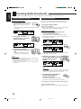
Turning the Power On and Off (Standby)
On the front panel:
To turn on the power, press POWER.
The STANDBY lamp goes off. The name of the
current source (or station frequency) appears on
the display.
To turn off the power (into standby mode),
press POWER again.
The STANDBY lamp lights up. A small amount
of power is consumed in standby mode. To turn
the power off completely, unplug the AC power
cord.
From the remote control:
To turn on the power, press AUDIO POWER.
The STANDBY lamp goes off. The name of the
current source (or station frequency) appears on
the display.
To turn off the power (into standby mode),
press AUDIO POWER again.
The STANDBY lamp lights up.
Selecting the Source to Play
Press one of the source selecting buttons.
On the front panel:
From the remote control:
Basic Operations
The following operations are commonly used when you play any sound source.
DVD Select the DVD player for viewing the stereo
digital video disc.
TV SOUND/DBS Select the TV sound (or the DBS tuner).
VCR Select the video component connected to the
VCR jacks.
CD * Select the CD player.
TAPE/MD * Select the cassette deck (or the MD recorder).
PHONO * Select the turntable.
FM/AM * Select an FM or AM broadcast.
• Each time you press the button, the band
alternates between FM and AM.
Notes:
• When connecting an MD recorder (to the TAPE/MD jacks) or a DBS
tuner (to the TV SOUND/DBS jacks), change the source name that
appears on the display. See page 11 for details.
• When you press one of the source selecting buttons on the remote
control marked above with an asterisk (
*
), the receiver
automatically turns on.
Signal and speaker indicators on the display
• The signal indicators light up to indicate the incoming channel
signals.
– Only the indicators for the incoming signals light up. (When
analog input is selected, “L” and “R” always light up.)
• The frame of the signal indicator (except for “LFE”: See notes
below) lights up if the corresponding speaker is set to “LARGE”
or “SMALL” (for subwoofer, “YES”).
L: Light up when the left front channel signal comes in.
The frame of this signal indicator always lights up.
R: Light up when the right front channel signal comes in.
The frame of this signal indicator always lights up.
C: Light up when the center channel signal comes in.
LS: Light up when the left rear channel signal comes in.
RS: Light up when the right rear channel signal comes in.
S: Light up when the monaural rear channel signal comes in.
LFE: Light up when the LFE channel signal comes in.
Notes:
• When the
LFE
channel signal comes in, “LFE” lights up.
• When “SUBWOOFER” is set to “YES,” (See page 15)
SUBWFR
lights up.
STANDBY
POWER
Selected source name appears
Current source name appears
Current volume level is shown here
STANDBY
POWER
AUDIO
DVD
CD
TV SOUND/DBS
TAPE/MD
VCR
PHONO
SOURCE NAME
SOURCE NAME
FM/AM
TV SOUND/ DBS
VCR
CD
PHONO
DVD
TAPE/MD FM/AM
S
C
LS
L
LFESUBWFR
RS
R
EN08_17.RX-6500V[J] 99.12.16, 1:08 PM8

9
English
Selecting different sources for picture and sound
You can watch picture from a video component while listening to
sound from another component. Press one of the audio source
selecting buttons (CD, TAPE/MD, PHONO, FM/AM, TV
SOUND*), while viewing the picture from a video component such
as the VCR or DVD player, etc.
On the front panel:
From the remote control:
Notes:
• Once you have selected a video source, pictures of the selected
source are sent to the TV until you select another video source.
*
Except when your TV is connected through the AV COMPU LINK
remote control system (see page 27).
Adjusting the Volume
On the front panel:
To increase the volume, turn MASTER
VOLUME clockwise.
To decrease the volume, turn it
counterclockwise.
• When you turn MASTER VOLUME rapidly,
the volume level also changes rapidly.
• When you turn MASTER VOLUME slowly,
the volume level also changes slowly.
From the remote control:
To increase the volume, press VOLUME +.
To decrease the volume, press VOLUME –.
CAUTION:
Always set the volume to the minimum before starting any source. If
the volume is set at its high level, the sudden blast of sound energy
can permanently damage your hearing and/or ruin your speakers.
Note:
The volume level can be adjusted within the range of “0” (minimum) to
“80” (maximum).
SPEAKERS
_ ON — OFF
12
MUTING
CD
TV SOUND/DBS
TAPE/MD PHONO
SOURCE NAME
SOURCE NAME
FM/AM
CD
PHONO
TAPE/MD FM/AM
TV SOUND/ DBS
VOLUME
–
+
MASTER VOLUME
Selecting the Front Speakers
On the front panel ONLY:
When you have connected two pairs of the front
speakers, you can select which to use. Pressing
SPEAKERS 1 or SPEAKERS 2 activates the
respective set of speakers.
• To use the speakers connected to the FRONT SPEAKERS 1
terminals, press SPEAKERS 1 to set it in the _ ON position, and
press SPEAKERS 2 to set it in the — OFF position.
• To use the speakers connected to the FRONT SPEAKERS 2
terminals, press SPEAKERS 2 to set it in the _ ON position, and
press SPEAKERS 1 to set it in the — OFF position.
• To use both sets of the speakers, press SPEAKERS 1 and
SPEAKERS 2 to set them in the _ ON position.
• To use neither set of the speakers, press SPEAKERS 1 and
SPEAKERS 2 to set them in the — OFF position.
Note:
When only one set of the speakers is connected to either the FRONT
SPEAKERS
1
or
2
terminals, do not activate both pairs of the
speakers. If you do, no sound comes out of the front speakers.
Listening only with headphones
1. Connect a pair of headphones to the PHONES jack on the front
panel.
2. Press SPEAKERS 1 and SPEAKERS 2 to set them in the —
OFF position.
CAUTION:
Be sure to turn down the volume before connecting or putting on the
headphones, as high volume can damage both the headphones and
your hearing.
Note:
You cannot shut off the sound through the other speakers using the
SPEAKERS 1 and 2 buttons.
Muting the Sound
From the remote control ONLY:
Press MUTING to mute the sound through all
speakers and headphones connected.
“MUTING” appears on the display and the
volume turns off (the volume level indicator goes
off).
To restore the sound, press MUTING again so that “OFF” appears
on the display.
• Turning MASTER VOLUME or pressing VOLUME +/– also
restores the sound.
EN08_17.RX-6500V[J] 99.12.16, 1:08 PM9

10
English
Adjusting the Subwoofer Output Level
You can adjust the subwoofer output level if you have selected
“YES” for the “SUBWOOFER” (see page 15).
Once it has been adjusted, the receiver memorizes the adjustment.
Before you start, remember...
• There is a time limit in doing the following steps. If the setting is
canceled before you finish, start from step 1 again.
On the front panel:
1. Press ADJUST repeatedly until
“SUBWFR LEVEL” appears on
the display.
• Once you have pressed ADJUST, MULTI CURSOR % / fi
can be also used for selecting “SUBWFR LEVEL.”
• The display changes to show the current setting.
2. Press MULTI CURSOR @ / # to
adjust the subwoofer output level
(–10 dB to +10 dB).
From the remote control:
1. Press SOUND.
The 10 keys are activated for sound adjustments.
2. Press SUBWOOFER –/+ to adjust
the subwoofer output level (–10 dB
to +10 dB).
Attenuating the Input Signal
When the input level of the playing source is too high, the sounds
will be distorted. If this happens, you need to attenuate the input
signal level to prevent the sound distortion.
On the front panel ONLY:
Press and hold INPUT ATT. (ONE TOUCH
OPERRATION) so that the ATT indicator
lights up on the display.
• Each time you press and hold the button, the
Input Attenuator mode turns on (“INPUT ATT
ON”) or off (“INPUT NORMAL”).
Notes:
• This function is available only for the sources connected using the
analog terminals.
• This function does not take effect when digital input is selected.
Reinforcing the Bass
With this Bass Boost function, you can boost the bass level.
Before you start, remember...
• There is a time limit in doing the following steps. If the setting is
canceled before you finish, start from step 1 again.
On the front panel ONLY:
1. Press ADJUST repeatedly until
“BASSBOOST” (with the current
setting) appears on the display.
• Once you have pressed ADJUST, MULTI CURSOR % / fi
also can be used for selecting “BASSBOOST.”
2. Press MULTI CURSOR @ / # to
switch this function “ON” or
“OFF.”
• When this function is switched “ON,” the
BASS BOOST indicator on the display
lights up.
Note:
The Bass Boost function affects the front speaker sounds only.
Adjusting the Tone
You can adjust the treble and bass sounds as you like.
Before you start, remember...
• There is a time limit in doing the following steps. If the setting is
canceled before you finish, start from step 1 again.
On the front panel ONLY:
1. Press ADJUST repeatedly until
“BASS” or “TREBLE” appears on
the display.
• Once you have pressed ADJUST, MULTI CURSOR % / fi
can be also used for selecting “BASS” or “TREBLE.”
• Select “BASS” to adjust the bass sound level.
• Select “TREBLE” to adjust the treble sound level.
2. Press MULTI CURSOL @ / # to
adjust the bass or treble sound
level within the range of –10 to
+10.
• Each time you press the button, the sound
level changes by ± 2 steps.
MULTI CURSOR
ADJUST
ADJUST
MULTI CURSOR
ONE TOUCH OPERATION/
INPUT ATT.
ADJUST
1
2
SUBWOOFER
MULTI CURSOR
SOUND
EN08_17.RX-6500V[J] 99.12.16, 1:08 PM10

11
English
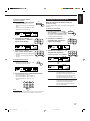
Changing the Source Name
When you have connected the MD recorder to the TAPE/MD jacks
or the DBS tuner to the TV SOUND/DBS jacks on the rear panel,
change the source name shown on the display when you select the
MD recorder or the DBS tuner as the source.
On the front panel ONLY:
When changing the source name from “TAPE” to “MD”:
1. Press TAPE/MD.
• Make sure “TAPE” appears on the display.
2. Press and hold SOURCE NAME
(TAPE/MD) until “ASSGN. MD”
appears on the display.
To change the source name from “MD” to “TAPE,” repeat
the same procedure above (in step 1, make sure “MD” appears
on the display
).
When changing the source name from “TV SOUND” to “DBS”:
1. Press TV SOUND/DBS.
• Make sure “TV SOUND” appears on the
display.
2. Press and hold SOURCE NAME
(TV SOUND/DBS) until “ASSGN.
DBS” appears on the display.
To change the source name from “DBS” to “TV SOUND,”
repeat the same procedure above (in step 1, make sure “DBS”
appears on the display).
Note:
Without changing the source name, you can still use the connected
components. However, there may be some inconvenience.
– “TAPE” or “TV SOUND” will appear on the display when you select
the MD recorder or DBS tuner.
– You cannot select the digital input (see page 14) for the MD
recorder and the DBS tuner.
– You cannot use the COMPU LINK remote control system (see page
26) to operate the MD recorder.
Recording a Source
For analog-to-analog recording
You can record any source playing through the receiver to a cassette
deck (or an MD recorder) connected to the TAPE/MD jacks and the
VCR connected to the VCR jacks at the same time.
While recording, you can listen to the selected sound source at
whatever sound level you like, without affecting the sound levels of
the recording.
For digital-to-digital recording
You can record the selected digital input through the receiver to a
digital recording device connected to the DIGITAL OUT terminal.
• Analog-to-digital and digital-to-analog recordings are not
possible.
• When the source is the digital recording equipment such as an
MD, only linear PCM signals can be recorded.
While recording, you can listen to the selected sound source at
whatever sound level you like, without affecting the sound levels of
the recording.
Notes:
• The output volume level, tone adjustment (see page 10) and bass
boost (see page 10) cannot affect the recording.
• The following signals do not come out through the DIGITAL OUT
terminal:
• Test tone signal
• Signals processed with the DSP modes
IMPORTANT:
• During recording, do not change the DSP mode (see page 18);
otherwise, recording will be interrupted.
• During digital-to-digital recording, do not output the test tone
signal (see page 26, 28); otherwise, your recording will be
interrupted.
Adjusting the Front Speaker Output
Balance
If the sounds you hear from the front right and left speakers are
unequal, you can adjust the speaker output balance.
Before you start, remember...
• There is a time limit in doing the following steps. If the setting is
canceled before you finish, start from step 1 again.
On the front panel ONLY:
1. Press ADJUST repeatedly until
“L/R BALANCE” appears on the
display.
• Once you have pressed ADJUST, MULTI CURSOR % / fi can
be also used for selecting “L/R BALANCE.”
2. Press MULTI CURSOR @ / # to
adjust the balance.
• Pressing @ decreases the right channel
output (from “L-21” to “R-21”).
• Pressing # decreases the left channel
output (from “R-21” to “L-21”).
Basic Settings
Some of the following settings are required after connecting and positioning your speakers in your listening room, while
others will make operations easier.
TV SOUND/DBS
SOURCE NAME
TAPE/MD
SOURCE NAME
MULTI CURSOR
ADJUST
EN08_17.RX-6500V[J] 99.12.16, 1:08 PM11

12
English
Setting the Speakers for the DSP Modes
To obtain the best possible surround sound of the DSP (Digital
Signal Processor) modes (see page 18), you have to register the
information about the speakers arrangement after all connections are
completed.
Before you start, remember...
• There is a time limit in doing the following steps. If the setting is
canceled before you finish, start from step 1 again.
Front, Center, and Rear Speaker Setting
Register the sizes of all the connected speakers.
On the front panel ONLY:
1. Press SETTING repeatedly until
“FRONT SPK” (Front Speaker),
“CENTER SPK” (Center
Speaker), or “REAR SPK” (Rear
Speaker) appears on the display.
• Once you have pressed SETTING, MULTI
CURSOR % / fi can be also used for
selecting the speakers.
2. Press MULTI CURSOR @ / # to
select the appropriate item about
the speaker selected in the above
step.
LARGE: Select this when the speaker size is relatively large.
SMALL: Select this when the speaker size is relatively small.
NONE: Select this when you have not connected a speaker.
(Not selectable for the front speakers)
3. Repeat steps 1 and 2 to select the appropriate
items for the other speakers.
Notes:
• Keep the following comment in mind as reference when adjusting.
– If the size of the cone speaker unit built in your speaker is greater
than 12 cm, select “LARGE,” and if it is smaller than 12 cm,
select “SMALL.”
• If you have selected “NO” for the subwoofer setting, you can only
select “LARGE” for the front speaker setting.
• If you have selected “SMALL” for the front speaker setting, you
cannnot select “LARGE” for the center and rear speaker settings.
• When you change your speakers, you need to register the
information about the speaker again.
SETTING
MULTI CURSOR
MULTI CURSOR
SETTING
LARGE
SMALL NONE
MULTI CURSOR
Center Delay Time Setting
Register the delay time of the sound from the center speaker,
comparing that of the sound from the front speakers.
If the distance from your listening point to the center speaker is
equal to that to the front speakers, select 0 msec. As the distance to
the center speaker becomes shorter, increase the delay time.
• 1 msec increase (or decrease) in delay time corresponds to 30 cm
decrease (or increase) in distance.
• When shipped from the factory, delay time is set to 0 msec.
On the front panel ONLY:
1. Press SETTING repeatedly until
“CENTER DELAY” appears on
the display.
• Once you have pressed SETTING, MULTI CURSOR % / fi
can be also used for selecting “CENTER DELAY.”
• The display changes to show the current setting.
2. Press MULTI CURSOR @ / # to
select the delay time of the center
speaker output.
• Pressing # increases the delay time from
0 msec (“C. DELAY: 0ms”) to 5 msec (“C.
DELAY: 5ms”).
• Pressing @ decreases the delay time from
5 msec (“C. DELAY: 5ms”) to 0 msec (“C.
DELAY: 0ms”).
Rear Delay Time Setting
Register the delay time of the sound from the rear speakers,
comparing that of the sound from the front speakers.
If the distance from your listening point to the rear speakers is equal
to that to the front speakers, select 0 msec. As the distance to the rear
speakers becomes shorter, increase the delay time.
• 1 msec increase (or decrease) in delay time corresponds to 30 cm
decrease (or increase) in distance.
• Rear delay time for Dolby Digital and DTS Digital Surround is to
be set to 5 msec.
• When shipped from the factory, delay time is set to 5 msec.
On the front panel ONLY:
1. Press SETTING repeatedly until
“REAR DELAY” appears on the
display.
• Once you have pressed SETTING, MULTI CURSOR % / fi
can be also used for selecting “REAR DELAY.”
• The display changes to show the current setting.
2. Press MULTI CURSOR @ / # to
select the delay time of the rear
speaker output.
• Pressing # increases the delay time from
0 msec (“R. DELAY: 0ms”) to 15 msec
(“R. DELAY: 15ms”).
• Pressing @ decreases the delay time from
15 msec (“R. DELAY: 15ms”) to 0 msec
(“R. DELAY: 0ms”).
SETTING
EN08_17.RX-6500V[J] 99.12.16, 1:08 PM12

13
English
Crossover Frequency Setting
Small speaker cannot reproduce the bass sound very well. So, if you
have used a small speaker any for the front, center, or rear channels,
this receiver automatically reallocates the bass elements, originally
assigned to the channel for which you have connected the small
speaker, to another channel (for which you have connected the large
speaker).
If you have selected “LARGE” for all speakers (see page 12), this
function will not take effect. To use this function properly, you need
to set this crossover frequency level according to the size of the
small speaker connected.
This function takes effect in the following cases:
- When playing a source using Dolby Pro Logic, Dolby Digital,
or DTS Digital Surround.
- When using the DAP modes.
On the front panel ONLY:
1. Press SETTING repeatedly until
“CROSSOVER FRQ” (Crossover
Frequency) appears on the display.
• Once you have pressed SETTING, MULTI CURSOR % / fi
can be also used for selecting “CROSSOVER FRQ.”
• The display changes to show the current setting.
2. Press MULTI CURSOR @ / # to
select the crossover frequency level
according to the size of the small
speaker connected.
• As you press it, the display changes to show the following:
• Use the following comments as reference when adjusting.
80Hz: Select this when the cone speaker unit built in the
speaker is about 12 cm.
100Hz: Select this when the cone speaker unit built in the
speaker is about 10 cm.
120Hz: Select this when the cone speaker unit built in the
speaker is about 8 cm.
SETTING
MULTI CURSOR
80Hz 100Hz 120Hz
Low Frequency Effect Attenuator Setting
If the bass sound is distorted while playing back a source using
Dolby Digital or DTS Digital Surround, follow the procedure below.
• This function takes effect only when the subwoofer (LFE) signals
come in. (with “SUBWOOFER” set to “Yes.”)
On the front panel ONLY:
1. Press SETTING repeatedly until
“LFE ATT” (Low Frequency
Effect Attenuator) appears on the
display.
• Once you have pressed SETTING, MULTI CURSOR % / fi
can be also used for selecting “LFE ATT.”
• The display changes to show the current setting.
2. Press MULTI CURSOR @ / # to
select the low frequency effect
attenuator level.
• As you press it, the display changes to
show the following:
0dB: Normally select this.
10dB: Select this when the bass sound is distorted.
Dynamic Range Compression Setting
You can compress the dynamic range (difference between maximum
sound and minimum sound) of the reproduced sound. This is useful
when enjoying surround sound at night.
• This function takes effect only when playing back a source using
Dolby Digital.
On the front panel ONLY:
1. Press SETTING repeatedly until
“D. RANGE COMP.” (Dynamic
Range Compression) appears on
the display.
• Once you have pressed SETTING, MULTI CURSOR % / fi
can be also used for selecting “D. RANGE COMP.”
• The display changes to show the current setting.
2. Press MULTI CURSOR @ / # to
select the appropriate item about
the compression level.
• As you press it, the display changes to
show the following:
OFF: Select this when you want to enjoy surround with its
full dynamic range. (No effect applied)
MID: Select this when you want to reduce the dynamic
range a little. (Factory setting)
MAX: Select this when you want to apply the compression
effect fully. (Useful at night)
SETTING
MULTI CURSOR
0dB 10dB
OFF MID MAX
SETTING
MULTI CURSOR
EN08_17.RX-6500V[J] 99.12.16, 1:08 PM13

14
English
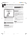
Digital Input (DIGITAL IN) Terminal
Setting
When you use the digital input terminals, you have to register what
components are connected to which terminals (DIGITAL IN 1/2/3).
Before you start, remember...
• There is a time limit in doing the following steps. If the setting is
canceled before you finish, start from step 1 again.
On the front panel ONLY:
1. Press SETTING repeatedly until
“DIGITAL IN” appears on the
display.
• Once you have pressed SETTING, MULTI
CURSOR % / fi can be also used for
selecting “DIGITAL IN.”
• The display changes to show the current setting.
2. Press MULTI CURSOR @ / # to
select an appropriate setting.
• As you press it, the display changes to show
the following:
1 DVD 2 CD 3 DBS “ 1 DVD 2 CD 3 MD “
1 DVD 2 MD 3 DBS “ 1 CD 2 DVD 3 DBS “
1 CD 2 DVD 3 MD “ 1 CD 2 MD 3 DBS “
1 DBS 2 CD 3 DVD “ 1 DBS 2 CD 3 MD “
1 DVS 2 DVD 3 MD “ 1 MD 2 CD 3 DBS “
1 MD 2 CD 3 DVD “ 1 MD 2 DVD 3 DBS “
(back to the beginning)
Note:
When shipped from the factory, the DIGITAL IN terminals can be used
as the digital input for the following components.
• DIGITAL 1 (coaxial): For DVD player
• DIGITAL 2 (optical): For CD player
• DIGITAL 3 (optical): For DBS tuner
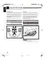
Selecting the Analog or Digital Input Mode
When you have connected some digital source components using the
digital terminals (see page 7), you need to change the input mode for
these components to the appropriate digital input mode correctly —
AUTO/PCM, DOLBY DIGITAL, or DTS.
Once the correct mode is selected for each digital source
component, the mode is memorized until you change it.
1. Follow the steps in “Digital Input (DIGITAL IN)
Terminal Setting” to the left.
2. Press the source selecting button (CD, TAPE/MD,
TV SOUND/DBS, or DVD) for which you want to
change the input mode from analog input to
digital input.
3. Press ANALOG/DIGITAL repeatedly until the
digital input mode you want appears on the
display.
Each time you press the button, the input mode changes as
follows:
Normally select “AUTO/PCM,” so the receiver automatically
detects the incoming digital signal. The DIGITAL AUTO
indicator lights up on the display. (The DIGITAL AUTO lamp
next to the ANALOG/DIGITAL button lights up.)
- When the receiver can recognize the digital signal coming
into the receiver, the frame of the digital signal indicator for
the detected signal lights up automatically.
- When the receiver cannot recognize the incoming signal
correctly, the frame of the digital signal indicator flashes.
If this happens, select the same digital input mode with the
incoming digital signal — either “DOLBY DIGITAL” or
“DTS.”
Notes:
• Noise may come out of the speakers while searching or skipping a
multi-sound source encoded with Dolby Digital or DTS Digital
Surround. If this happens, select “DOLBY DIGITAL” or “DTS” for
digital input mode. (See above)
• When you change the source, the digital input mode will be
automatically reset to “AUTO/PCM.”
SETTING
DIGITAL 2 terminal setting
DIGITAL 1 terminal setting DIGITAL 3 terminal setting
MULTI CURSOR
On the front panel
TV SOUND/ DBS
CD
DVD
TAPE/MD
DVD
CD
TV SOUND/DBS
TAPE/MD
SOURCE NAME
SOURCE NAME
On the remote control
DIGITAL AUTO
ANALOG/DIGITAL
ANALOG/DIGITAL
On the front panel On the remote control
ANALOG
DTS
AUTO/PCM
DOLBY DIGITAL
(Digital)
(Digital)(Digital)
EN08_17.RX-6500V[J] 99.12.16, 1:08 PM14

15
English
To cancel the One Touch Operation function
Press ONE TOUCH OPERATION (INPUT ATT.) so that the ONE
TOUCH OPERATION indicator goes off.
(Even though the One Touch Operation function is canceled, the
recalled sound effects remain active.)
Note:
If the source is FM or AM, you can assign a different setting for each
band.
Using the Sleep Timer
Using the Sleep Timer, you can fall asleep to music and know the
receiver will turn off by itself rather than play all night.
From the remote control ONLY:
Press SLEEP repeatedly.
The SLEEP indicator lights up on the display,
and the shut-off time changes as follows (in
minutes):
When the shut-off time comes
The receiver turns off automatically.
To check or change the time remaining until the shut-off time
Press SLEEP once.
The remaining time until the shut-off time appears in minutes.
• To change the shut-off time, press SLEEP repeatedly.
To cancel the Sleep Timer
Press SLEEP repeatedly until “SLEEP 00min.” appears on the
display. (The SLEEP indicator goes off.)
• Turning off the power also cancels the Sleep Timer.
Setting the Subwoofer Information
Register whether or not you have connected a subwoofer.
Before you start, remember...
• There is a time limit in doing the following steps. If the setting is
canceled before you finish, start from step 1 again.
On the front panel ONLY:
1. Press SETTING repeatedly until
“SUBWOOFER” appears on the
display.
• Once you have pressed SETTING, MULTI CURSOR % / fi
can be also used for selecting “SUBWOOFER.”
• The display changes to show the current setting.
2. Press MULTI CURSOR % / fi to
select “YES” or “NO.”
YES: Select this when a subwoofer is used.
NO: Select this when no subwoofer is used.
Storing the Basic Settings and
Adjustments — One Touch Operation
JVC’s One Touch Operation function is used to assign and store
different sound settings for each different playing source. By using
this function, you do not have to change the settings every time you
change the source. The stored settings for the newly selected source
are automatically recalled.
The following can be stored for each source:
• Volume level (see page 9)
• Bass boost (see page 10)
• Tone adjustment (see page 10)
• Input attenuator mode (see page 10)
• Subwoofer output level (see page 10)
• Balance (see page 11)
• DSP modes
– 3D-PHONIC mode settings (see page 21)
– DAP mode settings (see page 21)
– Surround mode settings (see page 22)
On the front panel ONLY:
To store the sound settings
1. Press ONE TOUCH OPERATION
(INPUT ATT.) so that the ONE
TOUCH OPERATION indicator
lights up on the display.
2. Adjust the sound using the functions listed above.
The newly adjusted settings are memorized.
To recall the sound settings
With the ONE TOUCH OPERATION lamp lit, the settings for the
currently selected source are recalled when the source is selected.
SETTING
MULTI CURSOR
SLEEP
2010 30 40 50 60 70 80 90
(Canceled)
00
ONE TOUCH OPERATION/
INPUT ATT.
EN08_17.RX-6500V[J] 99.12.16, 1:08 PM15

16
English
Using Preset Tuning
Once a station is assigned to a channel number, the station can be
quickly tuned. You can preset up to 30 FM and 15 AM stations.
To store the preset stations
Before you start, remember...
• There is a time limit in doing the following steps. If the setting is
canceled before you finish, start from step 1 again.
On the front panel ONLY:
1. Tune in the station you want to preset (see
“Tuning in Stations Manually”).
If you want to store the FM reception mode for this station,
select the FM reception mode you want. See “Selecting the FM
Reception Mode” on page 17.
2. Press MEMORY.
“CH-” appears and the channel number position starts flashing
on the display for about 5 seconds.
3. Press MULTI CURSOR @ / # to
select a channel number while the
channel number position is
flashing.
Note:
You can use the 10 keys on the remote control to select the preset
number. When using the 10 keys, be sure that they are activated
for the tuner, not for the CD and others. (See page 29.)
4. Press MEMORY again while the
selected channel number is
flashing on the display.
The selected channel number stops flashing.
The station is assigned to the selected channel number.
5. Repeat steps 1 to 4 until you store all the stations you want.
To erase a stored preset station
Storing a new station on a used number erases the previously stored
one.
Tuning in Stations Manually
On the front panel ONLY:
1. Press FM/AM to select the band.
The MULTI CURSOR % / fi / @ / #
buttons can be now used for operating the
tuner.
• Each time you press the button, the band alternates between
FM and AM.
2. Press MULTI CURSOR % / fi
repeatedly until “ – TUNING +”
appears on the display.
3. Press MULTI CURSOR @ / #
until you find the frequency you
want.
• Pressing @ decreases the frequency.
• Pressing # increases the frequency.
Notes:
• When you hold MULTI CURSOR
@
/
#
in step 3, the frequency
keeps changing until a station is tuned in.
• When a station of sufficient signal strength is tuned in, the TUNED
indicator lights up on the display.
When an FM stereo program is received, the STEREO indicator
also lights up.
Receiving Radio Broadcasts
You can browse through all the stations or use the preset function to go immediately to a particular station.
MEMORY
MULTI CURSOR
MEMORY
FM/AM
MULTI CURSOR
MULTI CURSOR
EN08_17.RX-6500V[J] 99.12.16, 1:09 PM16

17
English
Selecting the FM Reception Mode
When an FM stereo broadcast is hard to
receive or noisy
You can change the FM reception mode while receiving an FM
broadcast.
On the front panel ONLY:
1. If necessary, press FM/AM so that the
MULTI CURSOR % / fi / @ / # buttons
can be now used for operating the tuner.
• Each time you press the button, the band
alternates between FM and AM.
2. Press MULTI CURSOR % / fi
repeatedly until “FM MODE”
appears on the display.
3. Press MULTI CURSOR @ / # to
switch the FM reception to
“AUTO MUTING” or “MONO.”
AUTO MUTING: When a program is broadcasted in stereo,
you will hear stereo sound; when in
monaural, you will hear monaural sounds.
This mode is also useful to suppress static
noise between stations. The AUTO
MUTING indicator lights up on the display.
MONO: Reception will be improved although you
will lose the stereo effect. In this mode, you
will hear noise while tuning into the
stations. The AUTO MUTING indicator
goes off on the display.
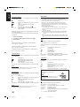
To tune in a preset station
On the front panel:
1. Press FM/AM to select the band.
• The MULTI CURSOR % / fi / @ / #
buttons can be now used for operating the
tuner.
• Each time you press the button, the band
alternates between FM and AM.
2. Press MULTI CURSOR % / fi
repeatedly until “ – PRESET +”
appears on the display.
3. Press MULTI CURSOR @ / # to
select a preset channel station.
• Pressing @ decreases the preset channel
number.
• Pressing # increases the preset channel
number.
From the remote control:
1. Press FM/AM.
• Each time you press the button, the band
alternates between FM and AM.
2. Press 10 keys to select a preset channel number.
• For channel number 5, press 5.
• For channel number 15, press +10 then 5.
• For channel number 20, press +10 then 10.
• For channel number 30, press +10, +10,
then 10.
Note:
When you use the 10 keys on the remote control, be sure that they are
activated for the tuner, not for the CD and others. (See page 29.)
FM/AM
MULTI CURSOR
MULTI CURSOR
FM/AM
FM/AM
MULTI CURSOR
MULTI CURSOR
TEST
100+
EFFECT
1
2
3
4
5
6
7
/P
8
9
0
10
+10
CNTR
REAR•L
REAR•R
SUBWOOFER
MENU
ENTER
RETURN
EN08_17.RX-6500V[J] 99.12.16, 1:09 PM17
Page is loading ...
Page is loading ...
Page is loading ...
Page is loading ...
Page is loading ...
Page is loading ...
Page is loading ...
Page is loading ...
Page is loading ...
Page is loading ...
Page is loading ...
Page is loading ...
Page is loading ...
Page is loading ...
Page is loading ...
Page is loading ...
Page is loading ...
Page is loading ...
Page is loading ...
Page is loading ...
Page is loading ...
-
 1
1
-
 2
2
-
 3
3
-
 4
4
-
 5
5
-
 6
6
-
 7
7
-
 8
8
-
 9
9
-
 10
10
-
 11
11
-
 12
12
-
 13
13
-
 14
14
-
 15
15
-
 16
16
-
 17
17
-
 18
18
-
 19
19
-
 20
20
-
 21
21
-
 22
22
-
 23
23
-
 24
24
-
 25
25
-
 26
26
-
 27
27
-
 28
28
-
 29
29
-
 30
30
-
 31
31
-
 32
32
-
 33
33
-
 34
34
-
 35
35
-
 36
36
-
 37
37
-
 38
38
-
 39
39
-
 40
40
-
 41
41


Ask a question and I''ll find the answer in the document
Finding information in a document is now easier with AI
Related papers
Other documents
-
Eltax AVR-900 User manual
-
HP Home Theater Audio System User manual
-
RCA 7-Piece 600-Watt Home Theater Audio System User manual
-
Technicolor - Thomson Stereo Receiver DPL5000 User manual
-
-
-
Hitachi HTADD3WAU User manual
-
-
Sherwood RV-4060 User manual
-