Page is loading ...

45521A
Printed in Canada 01-05-2011
ROCKET E.P.A. WOOD STOVE
OWNER’S MANUAL
US ENVIRONMENTAL
PROTECTION AGENCY PHASE
II CERTIFIED WOOD STOVE
Safety tested according to ULC
S627 and UL 1482 Standards
by:
READ AND KEEP THIS MANUAL FOR REFERENCE
STOVE BUILDER INTERNATIONAL INC.
250, de Copenhague, Saint-Augustin-de-Desmaures (Quebec), Canada G3A 2H3
Tel: (418) 878-3040
Fax: (418) 878-3001
This manual is available for free download on the manufacturer’s web site. It is a copyrighted
document. Re-sale is strictly prohibited. The manufacturer may update this manual from time
to time and cannot be responsible for problems, injuries, or damages arising out of the use
of information contained in any manual obtained from unauthorized sources.

2
INTRODUCTION
Stove Builder International, one of the most important wood stove and fireplace
manufacturers in North America, congratulates you on your purchase and wishes to help
you get maximum satisfaction from your wood stove. In the pages that follow, we will
give you advice on wood heating and controlled combustion as well as technical
specifications regarding installation, operation and maintenance of the model you have
chosen.
The instructions pertaining to the installation of your wood stove in North America
comply with ULC-S627 and UL-1482 standards.
Read this entire manual before you install and use your new stove. If this stove is
not properly installed, a house fire may result. To reduce the risk of fire, follow
the installation instructions. Failure to follow instructions may result in property
damage, bodily injury, or even death.
Consult your municipal building department or fire officials about restrictions and
installation requirements in your area and the need to obtain a permit.
KEEP THIS INSTRUCTION MANUAL FOR FUTURE REFERENCE.
CAUTIONS:
HOT WHILE IN OPERATION. KEEP CHILDREN, CLOTHING AND FURNITURE AWAY. CONTACT
MAY CAUSE SKIN BURNS.
DO NOT USE CHEMICALS OR FLUIDS TO IGNITE THE FIRE.
DO NOT LEAVE THE STOVE UNATTENDED WHEN THE DOOR IS SLIGHTLY OPENED DURING
IGNITION.
DO NOT BURN WASTE, FLAMMABLE FLUID SUCH AS GASOLINE, NAPHTHA, OR MOTOR OIL.
DO NOT CONNECT TO ANY AIR DISTRIBUTION DUCT OR SYSTEM.
ALWAYS CLOSE THE DOOR AFTER IGNITION.
DO NOT INSTALL IN A MOBILE HOME
REGISTER YOU WARRANTY ONLINE
To receive full warranty coverage, you will need to show
evidence of the date you purchased your stove. Keep your
sales invoice. We also recommend that you register your
warranty online at
www.drolet.ca
Registering your warranty online will help us track rapidly
the information we need on your stove.

3
TABLE OF CONTENTS
SECTION 1.0 - INSTALLATION .............................................................. 4
1.1 GENERAL INSTALLATION ..................................................................................... 4
1.2 POSITIONING THE STOVE ................................................................................... 5
1.3 CLEARANCES TO COMBUSTIBLES AND FLOOR PROTECTOR ........................ 5
SECTION 2.0 CHIMNEY (FLUE SYSTEM) ......................................... 12
2.1 DEFINITIONS ....................................................................................................... 12
2.2 CHIMNEY ............................................................................................................. 12
2.2.1 Step by step installation of your factory-built chimney ...................................... 14
2.2.2 Typical installation through an existing masonry chimney ................................ 23
2.3 CHIMNEY CONNECTOR...................................................................................... 26
2.4 DRAFT .................................................................................................................. 28
2.5 OUTSIDE COMBUSTION AIR .............................................................................. 28
2.6 THE ADVANTAGE OF INSTALLING A BLOWER (FAN) ...................................... 29
SECTION 3.0 OPERATION ..................................................................... 30
3.1 SAFETY INFORMATION ...................................................................................... 30
3.2 FUEL .................................................................................................................... 32
3.2.1 The use of manufactured logs .......................................................................... 33
3.2.2 Simple wood moisture test ............................................................................... 33
3.3 NOTES ABOUT FIRST FIRING ............................................................................ 33
3.4 LIGHTING A FIRE ................................................................................................ 34
3.5 MAINTAINING THE FIRE ..................................................................................... 34
3.6 FAN (BLOWER) OPERATION .............................................................................. 35
SECTION 4.0 MAINTENANCE ............................................................... 36
4.1 CLEANING AND PAINTING YOUR STOVE ......................................................... 36
4.2 GASKETING ......................................................................................................... 36
4.3 ASH REMOVAL .................................................................................................... 36
4.4 CHIMNEY (FLUE) CLEANING .............................................................................. 37
4.5 DEALING WITH A CHIMNEY FIRE ...................................................................... 37
SECTION 5.0 FEATURES ........................................................................ 38
5.1 ROCKET STOVE .................................................................................................. 38
DROLET LIMITED LIFETIME WARRANTY..................................... 40

4
SECTION 1.0 - INSTALLATION
When installed and operated as described in these instructions, the E.P.A Rocket wood
stove is suitable for use as a freestanding wood stove in residential installations. The
E.P.A Rocket wood stove is not intended for installation in a bedroom or a mobile home.
In Canada, the CSA B365 Installation Code for Solid Fuel Burning Appliances and
Equipment and the CSA C22.1 Canadian National Electrical Code are to be followed in
the absence of local code requirements. In the USA, the ANSI NFPA 70 National
Electrical Code and NFPA 211 Standard for Chimneys, Fireplaces, Vents and Solid
Fuel-Burning Appliances are to be followed in the absence of local code requirements.
In addition to the national installation and/or local building codes, fire officials (or other
authorities having jurisdiction) should be contacted to determine what restrictions and
installation requirements might apply locally.
1.1 GENERAL INSTALLATION
CAUTIONS:
MIXING OF APPLIANCE OR FLUE SYSTEM COMPONENTS FROM DIFFERENT SOURCES OR
MODIFYING THE DIMENSIONAL SPECIFICATION OF COMPONENTS MAY RESULT IN
HAZARDOUS CONDITIONS. WHERE SUCH ACTION IS CONSIDERED, THE MANUFACTURER
SHOULD BE CONSULTED IN THE FIRST INSTANCE.
DO NOT CONNECT THIS UNIT TO ANY AIR DISTRIBUTION SYSTEM.
CRACKED AND BROKEN COMPONENTS, e.g. CERAMIC TILES, MAY RENDER THIS
INSTALLATION UNSAFE.
CONNECT THE STOVE ONLY TO A LINED MASONRY CHIMNEY CONFORMING TO NATIONAL
AND LOCAL BUILDING CODES FOR USE WITH SOLID FUEL, OR TO A LISTED FACTORY BUILT
CHIMNEY SUITABLE FOR USE WITH SOLID FUEL.
DO NOT INSTALL IN A MOBILE HOME.
WARNINGS:
A SOURCE OF FRESH AIR INTO THE ROOM OR SPACE HEATED SHALL BE PROVIDED WHEN
REQUIRED.

5
1.2 POSITIONING THE STOVE
It is very important to position the wood stove in an area that will favour the most efficient
heat distribution throughout the house. The stove should therefore be installed in the
room where the most time is spent, and in the most spacious room possible. Recall that
wood stoves produce radiating heat, the heat we feel when we are close to a wood
stove. A wood stove also functions by convection that is through the displacement of hot
air accelerated upwards and its replacement with cooler air at the floor level. The
stove’s convection effect is facilitated by the installation of a blower.
1.3 CLEARANCES TO COMBUSTIBLES AND FLOOR
PROTECTOR
To install your appliance correctly, it is extremely important to respect all clearances to
any combustibles as indicated on your stove’s certification label.
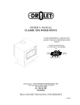
Clearances to combustible materials
(see figure 1.3 to match each letter to a clearance)
CLEARANCES (SINGLE WALL PIPE)
CANADA
USA
A
16" (410 mm)
16" (410 mm)
B
21" (535 mm)
21" (535 mm)
C
10" (255 mm)
7" (180 mm)
D
18" (460 mm)
18" (460 mm)
E
29" (740 mm)
29" (740 mm)
F
18" (460 mm)
15" (385 mm)
K
48’’ (1220 mm)
48’’ (1220 mm)
L
84’’ (213 cm)
84’’ (213 cm)
CLEARANCES (DOUBLE WALL PIPE)
CANADA
USA
A
16" (410 mm)
16" (410 mm)
B
21" (535 mm)
21" (535 mm)
C
7" (180 mm)
7" (180 mm)
D
18" (460 mm)
18" (460 mm)
E
29" (740 mm)
29" (740 mm)
F
15" (385 mm)
15" (385 mm)
K
48’’ (1220 mm)
48’’ (1220 mm)
L
84’’ (213 cm)
84’’ (213 cm)

6
FIGURE 1.3 Clearances to combustible materials and floor protection

7
Floor protector
If the stove is to be installed on top of a combustible floor, it must be guarded by a non
combustible material as shown on figure 1.3 (see the dotted line area).
FLOOR PROTECTOR*
CANADA
USA
G
8’’ (205 mm) – Note 1
N/A (Canada only)
H
8’’ (205 mm)
N/A (Canada only)
I
18’’ (460 mm)
From door opening
16’’ (410 mm)
From door opening
J
N/A (USA only)
8’’ (205 mm)
M
8’’ (205 mm)
N/A (Canada only)
N
N/A (USA only)
Note 2
*Steel with a minimum thickness of 0.015’’ (0.38 mm) or ceramic tiles sealed together with grout. No
protection is required if the unit is installed on a non-combustible floor (ex: concrete).
Note 1: The floor protection at the back of the stove is limited to the stove’s required
clearance if such clearance is smaller than 8 inches (203 mm).
Note 2: Only required under the horizontal section of the connector. Must exceed each
side of the connector by at least 2 inches (51 mm).
Reduced clearances using shielding
You may decrease the clearances by installing heat radiation shields between the walls
or the ceiling and the stove. These heat radiation shields must be installed permanently,
and can include sheet metal, a rigid non-combustible sheet or a masonry wall.
Clearances of not less than 1" (25 mm) and not more than 3" (76 mm) between the
bottom of the shield and the floor and not less than 3" (76 mm) between the top of the
shield and the ceiling must be respected to allow vertical air circulation behind the shield.
The shield must extend 20" (500 mm) above the stove top and 18" (450mm) to each
side of the stove (see Graphic 1).
Following the installation of such a heat radiation shield, the clearances mentioned on
the stove certification plate may be reduced as stated in the following table.

8
TYPE OF PROTECTION
Reducing Clearances
With Shielding
Sides and
Rear/Back
Top
Sheet metal, a minimum of 0,024" (0,61mm)
spaced out at least 1" (25mm) by non-combustible
spacers (see graphic 2).
67%
50%
Ceramic tiles, or an equivalent non-combustible
material on fire-proof supports spaced out at least
1" (25 mm) by non-combustible spacers (see
graphic 3).
50%
33%
Ceramic tiles, or an equivalent non-combustible
material on fire-proof supports with a minimum of
0,024" (0,61 mm) sheet metal backing spaced out
at least 1" (25 mm) by non-combustible spacers
(see graphic 4)
67%
50%
Brick spaced out at least 1" (25 mm) by non-
combustible spacers (see graphic 5)
50%
N/A
Brick with a minimum of 0,024" (0,61 mm) sheet
metal backing spaced out at least 1" (25 mm) by
non-combustible spacers (see graphic 6).
67%
N/A

9
Graphic 1
A- Minimum clearance required between the appliance and an unshielded combustible
ceiling.
B- 20 in. (500 mm) minimum;
C- 1 in. (25 mm) minimum;
D- Between 1 in. and 3 in. (25 mm and 75 mm);
E- 3 in. (75 mm) minimum;
F- 18 in. (457 mm) minimum.
1- Shielding;
2- Non-combustible spacers;
3- Ceiling protector;
4- Combustible wall;
5- Ceiling;
6- Appliance (side view);
7- Appliance (top view).

10
Graphic 2
A- 1 in.(25 mm) minimum;
1- Combustible wall;
2- Non-combustible spacers;
3- 0.024’’ (0.61mm) sheet metal.
Graphic 3
A- 1 in. (25 mm) minimum;
1- Combustible wall;
2- Non-combustible spacers;
3- Non-combustible support;
4- Ceramic tile or non-combustible material.
Graphic 4
A- 1 in. (25 mm) minimum;
1- Combustible wall;
2- Non-combustible spacer;
3- 0.024’’ (0.61 mm) thick sheet metal;
4- Non-combustible support;
5- Ceramic tile or non-combustible material.

11
Graphic 5
A- 1 in. (25 mm) minimum;
1- Combustible wall;
2- Non-combustible spacers;
3- Brick.
Graphique 6
A- 1 in. (25 mm) minimum;
1- Combustible wall;
2- Non-combustible spacers;
3- 0.024’’ (0.61 mm) thick sheet metal;
4- Brick.

12
SECTION 2.0 CHIMNEY (FLUE SYSTEM)
2.1 DEFINITIONS
For clarity, the following definitions should be used with respect to these instructions:
A chimney system consists of a connector off the top of the stove, and a
chimney, which attaches to the connector and terminates outside the house.
A chimney can be a masonry chimney (of masonry construction with an inside
liner), or a factory built chimney.
A factory built chimney can be a double wall chimney (two concentric pipes
with insulation - sometimes referred to as an insulated solid pack) or an air
cooled chimney (three concentric pipes, with insulation between the first and
second pipes, and air between the second and third pipes).
A single wall connector is a single pipe.
A double wall connector has two concentric pipes, no insulation, and is an air
cooled connector.
2.2 CHIMNEY
CAUTIONS:
DO NOT FILL ANY FRAMED SPACE AROUND THE FACTORY-BUILT CHIMNEY WITH
INSULATION OR ANY OTHER MATERIAL. INSULATION PLACED IN THIS AREA COULD CAUSE
ADJACENT COMBUSTIBLES TO OVERHEAT.
DO NOT USE MAKESHIFT COMPROMISES DURING INSTALLATION AS THEY MAY BE SAFETY
HAZARDS, AND A FIRE COULD RESULT.
DO NOT CONNECT THIS UNIT TO A CHIMNEY SYSTEM SERVING ANOTHER APPLIANCE.
DO NOT CUT RAFTERS OR CEILING JOISTS WITHOUT FIRST CONSULTING A BUILDING
OFFICIAL TO ENSURE STRUCTURAL INTEGRITY IS NOT COMPROMISED.
Your wood stove may be hooked up with a factory built or masonry chimney. If you are
using a factory built chimney, it must comply with UL103 (USA) or ULCS629 (Canada)
standards. It must therefore be a 6” (152mm) HT Type (2100°F) chimney. It is
extremely important that it be installed according to the manufacturer's specifications.
The manufacturers’ installation instructions and specified clearances should always be
followed in accordance with local and national installation codes. In Canada the CSA
B365 and the CSA C22.1 installation codes are to be followed. In the USA the ANSI
NFPA 70 and ANSI NFPA 211 installation codes are to be followed.

13
If you are using a masonry chimney, it is important that it be built in compliance with the
specifications of the Building Code. It must be lined with fire clay bricks, or clay tiles,
sealed together with fire cement, or have a listed solid fuel burning stainless steel liner.
Round chimneys are the most efficient.
The interior diameter of the chimney should be identical to the stove's smoke exhaust. A
chimney which is too small may cause draft problems, since it may not have the required
volume to properly evacuate the quantity of smoke resulting from the combustion. A
chimney which is too large may also cause draft problems. In fact, a large chimney will
be harder to warm-up and may not reach high enough temperatures to create a proper
draft effect. Note that it is the chimney which creates the draft effect, not your
stove. Your stove's performance is therefore directly dependent on an adequate
draft from your chimney.
The following recommendations may be useful for the installation of your chimney:
Do not connect your stove to a chimney serving another appliance.
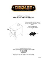
The chimney must rise above the roof at least 3' (0.9 mm) from the uppermost
point of contact. See Figure 2.2.
The chimney must exceed any part of the building or other obstruction within a
10' (3.04 m) distance by a height of at least 2' (0.6 m). See Figure 2.2.
The minimum overall height of the chimney system, measured from the stove top
to the exterior termination cap of the chimney should be at least 12' (3.66m). A
chimney which is too short may lack the “tunnel effect” required to obtain a
proper draft.
Installation of an interior chimney is always preferable to an exterior chimney.
Chimneys constructed outside of the home on an exterior wall should be avoided
if possible, especially in colder climates. The gas which circulates into an interior
chimney will cool more slowly, thus reducing the build-up of creosote and the risk
of flue fires.
All else being equal, cooler chimneys will have less draft than hotter ones. This
problem will be amplified if the chimney is excessively long. A chimney which is
excessively long may be very hard to warm-up due to its higher volume. A cool
chimney may even down draft (reverse flow) due to the difficulty in heating it up
to operating temperature while trying to evacuate the stack gases.
If an exterior chimney is used, the best results will be obtained by using a
connector vertically off the unit to the highest possible point before elbowing off
horizontally to the exterior chimney. For efficiency and safety reasons the stove
must not be installed with an insulated chimney connected directly to the
appliance.
Using a fire screen at the extremity of the chimney requires regular inspection in
order to insure that it is not obstructed, thus blocking the draft. It should be
cleaned when necessary.

14
FIGURE 2.2 Minimum Height of the Chimney
2.2.1 Step by step installation of your factory-built chimney
The way to install your chimney may vary from one chimney manufacturer to another. The
instructions contained in this manual are based on the recommendations of chimney
manufacturers whose products are sold at many North American retailers of wood stoves
and related heating accessories.
Wall support system
If your chimney must rise along an outside wall, you need to connect it to your stove
through an adjacent wall. In Canada the CSA B365 and the CSA C22.1 installation codes
are to be followed. For this type of installation, the following items are normally required:
Chimney
Suitable lengths of chimney (enough to go up to your roof)
An adjustable wall support
A wall thimble
An adequate number of wall bands (one for every 8 feet of chimney, excluding the
roof portion)
A stove pipe adapter
One insulated tee & plug
A roof flashing kit (if necessary)
A chimney cap.
Roof guys (if required)

15
Stove pipe
An adequate number of stove pipe sections.
A 90
o
elbow
Typical installation through the wall
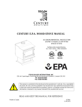
FIGURE 2.2.1 (A) Typical installation through the wall
1- Start by positioning your stove where you would like it to go, taking into account
the minimum clearances to combustible material. You will then be able to
determine where the chimney will pass through the wall. You will probably have to
adjust the stove position slightly to ensure that your chimney will run between the
studs. You can use a stud finder to locate the studs. Use a spoke saw or jig saw to
cut a hole, remembering that you need to maintain a clearance of 2 inches
between the chimney and any combustible materials. For concrete walls, cut a
hole slightly larger than the outer diameter of the chimney.

16
2- Once the opening completed, you need to frame in the area to allow for the
installation of a wall thimble. A wall thimble is not required for installations through
concrete walls.
3- You must first secure the wall thimble into the exterior wall surface. Then, do the
same inside and fasten the trim plate.
4- Then, from outside the building, slide a short chimney length (attached to the tee)
through the wall thimble. The chimney must extend at least 3 inches into the living
space where it attaches to the stove pipe.

17
5- You can now install the wall support. Simply slide the wall support up to the tee,
ensuring that the adapter on the support engages with the female coupler on the
bottom of the tee. When the wall support is level and properly positioned, you can
use lag bolts to secure it into the wall studs. To complete the installation, install an
insulated tee plug below the wall support.
6- You can start to add chimney sections. We recommend that you also use locking
bands to secure all connections. You will need to secure the chimney to the house
using wall bands. Wall bands wrap around the chimney and then attach to the
wall. Install the first one 3 feet above the wall support. Then, you will need
another band for each 8 feet of chimney. Note: if your chimney must be
installed through your soffit, install a roof flashing above and finishing plate
below where the roof is cut. Consult the following section called “CEILING
SUPPORT SYSTEM” for more details.
7- Authorities require that the chimney extend not less than 3 feet above the highest
point where it passes through the roof of a building and not less than 2 feet above
any portion of the building within 10 feet. If the chimney extends more than 5 feet
above the roof deck, roof guys with telescoping legs and draw bands are required.

18
8- Finally, twist on your rain cap and you can head back inside.
9- You are now ready to connect your chimney to your stove. Simply install the inter-
connecting stove pipe between the stove pipe adapter and the stove. You can
follow the instructions in the following section (section 2.3) of this manual called
« CHIMNEY CONNECTOR».
Ceiling support system
If your chimney must rise inside the house and go through the ceiling, you need to connect
it to your stove at the ceiling level. For this type of installation, the following items are
normally required:
Chimney
An adequate number of chimney sections (enough to go up to your roof)
A ceiling support kit with stove pipe adapter
An attic insulation shield
A roof flashing kit
A chimney cap
Roof guys (if necessary)
Stove pipe
Suitable lengths of stove pipe

19
Typical installation through the ceiling
FIGURE 2.2.1 (B) Typical Installation Through the Ceiling
1. Place your stove where you would like it located and use a plumb line to mark the
ceiling directly above your stove flue. You will probably have to adjust this position
slightly to ensure that your chimney will run between the joists. You can use a stud
finder to locate the joists. You also need to take into account the minimum
clearances to combustible materials. After you have determined where the
chimney will go through the ceiling, use a spoke saw or power jig saw to cut a hole,
remembering that you need a minimum 2-inch clearance between the chimney and
any combustible materials. Depending on whether you have a one or two story
structure, you will need to cut a matching hole through the floor of the attic or
second floor living space.

20
2. Before you install the ceiling support, you need to frame the area.
3. To install the ceiling support, just slide the assembly into the framed opening from
below. Once you ensure that the finishing plate is flush with the underside of the
ceiling and assembly is level, secure it with screws.
4. Once the support is secure, you can begin to assemble the chimney by lowering
the first section into the support. Make sure that the male coupler is pointing
upwards, as indicated by the arrow on the chimney label.
5. Then, from beneath the support, insert the stove pipe adapter and twist-lock it into
place.
/