Page is loading ...

2” OR 3” DIRTY WATER PUMP
65322
or
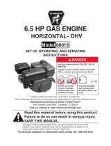
SET UP, OPERATING, AND SERVICING
INSTRUCTIONS
Using an engine indoors CAN KILL YOU IN
MINUTES.
Engine exhaust contains carbon monoxide.
This is a poison you cannot see or smell.
NEVER use inside
a home or garage,
EVEN IF doors and
windows are open.
Only use OUTSIDE
and far away from
windows, doors, and
vents.
Distributed exclusively by Harbor Freight Tools
®
.
3491 Mission Oaks Blvd., Camarillo, CA 93011
Visit our website at: http://www.harborfreight.com
Read this material before using this product.
Failure to do so can result in serious injury.
SAVE THIS MANUAL.
Copyright
©
2008 by Harbor Freight Tools
®
. All rights reserved. No portion of this manual or any artwork
contained herein may be reproduced in any shape or form without the express written consent of
Harbor Freight Tools. Diagrams within this manual may not be drawn proportionally. Due to continuing
improvements, actual product may differ slightly from the product described herein. Tools required for
assembly and service may not be included.
For technical questions or replacement parts, please call 1-800-444-3353.
65323

SKU 65322 or 65323 For technical questions, please call 1-800-444-3353. Page 2
Page # Contents
1 Cover and Contact Information
2 Table of Contents
3 - 6 Important Safety Information
6 Pump Specications
6-8 Unpacking and Set Up
7-9 Operating Instructions
7 Checking and Filling Engine Oil
8 Checking and Filling Fuel
8 Start Procedure
9 Break In Period
9 Pump Operation
10 Engine Controls and Indicators
11 - 12 Pre Operation Checks
12 Starting & Stopping the Engine
13 Technical Specications
13 - 19 Servicing
13 - 14 Engine Oil Change
14 Air Filter Element Maintenance
14 Spark Plug Maintenance
15 Fuel Filter Replacement
15 Cleaning, Maintenance and
Lube Schedule
16 Storage
17 - 18 Engine Troubleshooting
19 Pump Troubleshooting
19 Pump Parts List
20 Pump Assembly Diagram
Page # Contents
21 Crankcase Assembly Diagram
and Parts List
22 Crankcase Cover Assembly
Diagram and Parts List
23 Cylinder Head and Cover As-
sembly Diagram and Parts List
24 Crankshaft, Piston and Connect-
ing Rod Assembly Diagram and
Parts List
25 Camshaft and Rocker Valve As-
sembly Diagram and Parts List
26 Carburetor Assembly Diagram
and Parts List
27 Fuel Tank Assembly Diagram
and Parts List
28 Air Cleaner Assembly Diagram
and Parts List
29 Mufer Assembly Diagram and
Parts List
30 Recoil Starter Assembly Dia-
gram and Parts List
31 Regulator Control Assembly
Diagram and Parts List
32 Flywheel Assembly Diagram
and Parts List
33 Ignition Coil Assembly Diagram
and Parts List
34 Wiring Diagram
35 - 36 Warranty
CONTENTS

SKU 65322 or 65323 For technical questions, please call 1-800-444-3353. Page 3
SAVE THIS MANUAL
Keep this manual for the safety warn-
ings and precautions, assembly, operat-
ing, inspection, maintenance and cleaning
procedures. Write the product’s serial
number in the back of the manual near the
assembly diagram (or month and year of
purchase if product has no number). Keep
this manual and the receipt in a safe and
dry place for future reference.
IMPORTANT SAFETY
INFORMATION
In this manual, on the labeling,
and all other information
provided with this product:
This is the safety alert
symbol. It is used to alert
you to potential personal
injury hazards. Obey all
safety messages that
follow this symbol to avoid
possible injury or death.
DANGER indicates
a hazardous
situation which, if not
avoided, will result in death or
serious injury.
WARNING
indicates a
hazardous situation which, if
not avoided, could result in
death or serious injury.
CAUTION, used
with the safety
alert symbol, indicates a
hazardous situation which, if
not avoided, could result in
minor or moderate injury.
NOTICE is used to
address practices
not related to personal injury.
CAUTION, without
the safety alert
symbol, is used to address
practices not related to
personal injury.
WARNING! Read all instructions.
Failure to follow all instructions
listed below may result in re,
serious injury and/or DEATH.
The warnings and precautions
discussed in this manual cannot
cover all possible conditions and
situations that may occur. It must
be understood by the operator that
common sense and caution are
factors which cannot be built into
this product, but must be supplied
by the operator.
SAVE THESE INSTRUCTIONS
SET UP PRECAUTIONS
Gasoline fuel and fumes are amma-1.
ble, and potentially explosive. Use
proper fuel storage and handling pro-
cedures. Do not store fuel or other
ammable materials nearby.
Have multiple ABC class re extin-2.
guishers nearby.
Operation of this equipment may cre-3.
ate sparks that can start res around
dry vegetation.
A spark arrestor may be required.
The operator should contact local re
agencies for laws or regulations relat-
ing to re prevention requirements.
Set up and use only on a at, level, 4.
well-ventilated surface.

SKU 65322 or 65323 For technical questions, please call 1-800-444-3353. Page 4
Wear ANSI-approved safety goggles, 5.
heavy-duty work gloves, and dust
mask/respirator during set up.
Use only oil and fuel recommended 6.
in the “Specications” section of this
manual.
OPERATING PRECAUTIONS
1. CARBON MONOXIDE
HAZARD
Using an engine indoors
CAN KILL YOU IN
MINUTES.
Engine exhaust contains carbon
monoxide. This is a poison you
cannot see or smell.
NEVER use inside a home or garage,
EVEN IF doors and windows are
open.
Only
use OUTSIDE and far away from
windows, doors, and vents.
Keep children away from the equip-2.
ment, especially while it is operating.
Do not leave the equipment unat-3.
tended when it is running. Turn off
the equipment (and remove safety
keys, if available) before leaving the
work area.
Wear ANSI-approved safety goggles 4.
and hearing protection during use.
People with pacemakers should 5.
consult their physician(s) before
use. Electromagnetic elds in close
proximity to a heart pacemaker could
cause pacemaker interference or
pacemaker failure. Caution is neces-
sary when near the engine’s magneto
or recoil starter.
Use only accessories that are recom-6.
mended by Harbor Freight Tools for
your model. Accessories that may be
suitable for one piece of equipment
may become hazardous when used
on another piece of equipment.
Do not operate in explosive atmo-7.
spheres, such as in the presence of
ammable liquids, gases, or dust.
Gasoline-powered engines may ignite
the dust or fumes.
Stay alert, watch what you are doing 8.
and use common sense when operat-
ing this piece of equipment. Do not
use this piece of equipment while
tired or under the inuence of drugs,
alcohol or medication.
Do not overreach. Keep proper foot-9.
ing and balance at all times. This en-
ables better control of the equipment
in unexpected situations.
Use this equipment with both hands 10.
only. Using equipment with only
one hand can easily result in loss of
control.
Dress properly. Do not wear loose 11.
clothing or jewelry. Keep hair, cloth-
ing and gloves away from moving
parts. Loose clothes, jewelry or long
hair can be caught in moving parts.

SKU 65322 or 65323 For technical questions, please call 1-800-444-3353. Page 5
Parts, especially exhaust system 12.
components, get very hot during use.
Stay clear of hot parts.
Do not cover the engine or equipment 13.
during operation.
Keep the equipment, engine, and sur-14.
rounding area clean at all times.
Use the equipment, accessories, etc., 15.
in accordance with these instructions
and in the manner intended for the
particular type of equipment, taking
into account the working conditions
and the work to be performed. Use
of the equipment for operations differ-
ent from those intended could result
in a hazardous situation.
Do not operate the equipment with 16.
known leaks in the engine’s fuel sys-
tem.
This product contains or, when used, 17.
produces a chemical known to the
State of California to cause cancer
and birth defects or other reproduc-
tive harm. (California Health & Safety
Code § 25249.5, et seq.)
When spills of fuel or oil occur, they 18.
must be cleaned up immediately.
Dispose of uids and cleaning materi-
als as per any local, state, or federal
codes and regulations. Store oil rags
in a bottom-ventilated, covered, metal
container.
Keep hands and feet away from 19.
moving parts. Do not reach over or
across equipment while operating.
Before use, check for misalignment 20.
or binding of moving parts, breakage
of parts, and any other condition that
may affect the equipment’s operation.
If damaged, have the equipment
serviced before using. Many ac-
cidents are caused by poorly main-
tained equipment.
Use the correct equipment for the 21.
application. Do not modify the equip-
ment and do not use the equipment
for a purpose for which it is not in-
tended.
SERVICE PRECAUTIONS
Before service, maintenance, or 1.
cleaning:
Turn the engine switch to its a.
“OFF” position.
Allow the engine to completely b.
cool.
Then, remove the spark plug c.
wire(s) from the spark plug(s).
Keep all safety guards in place and in 2.
proper working order. Safety guards
include mufer, air cleaner, mechani-
cal guards, and heat shields, among
other guards.
Do not alter or adjust any part of 3.
the equipment or its engine that is
sealed by the manufacturer or dis-
tributor. Only a qualied service
technician may adjust parts that
may increase or decrease gov-
erned engine speed.
Wear ANSI-approved safety goggles, 4.
heavy-duty work gloves, and dust
mask/respirator during service.
Maintain labels and nameplates on 5.
the equipment. These carry impor-
tant information. If unreadable or
missing, contact Harbor Freight Tools
for a replacement.

SKU 65322 or 65323 For technical questions, please call 1-800-444-3353. Page 6
Have the equipment serviced by a 6.
qualied repair person using only
identical replacement parts. This will
ensure that the safety of the equip-
ment is maintained. Do not attempt
any service or maintenance proce-
dures not explained in this manual
or any procedures that you are un-
certain about your ability to perform
safely or correctly.
Store equipment out of the reach of 7.
children.
Follow scheduled engine and equip-8.
ment maintenance.
Refueling Precautions:9.
Do not smoke, or allow sparks, a.
ames, or other sources of ignition
around the equipment, especially
when refuelling.
Do not rell the fuel tank while the b.
engine is running or hot.
Do not ll fuel tank to the top. Leave c.
a little room for the fuel to expand as
needed.
Refuel in a well-ventilated area only.d.
SAVE THESE
INSTRUCTIONS.
PUMP SPECIFICATIONS
Inlet / Outlet Diameter
Model 65322 = 3”
Model 65323 = 2”
Maximum Flow in GPM
(Gallons per Minute)
Model 65322 = 345
Model 65323 = 235
Maximum Lift Suction
Model 65322 = 26’
Model 65323 = 23’
Maximum Head
Model 65322 = 85’
Model 65323 = 82’
Anti-Reverse Flow
Rubberized Flap on
Inlet Port
Note: Additional specications found in
the TECHNICAL ENGINE SPECIFI-
CATIONS chart in this manual.
The emission control system for
this engine is warranted for standards
set by the U.S. Environmental Protec-
tion Agency. For warranty information,
refer to the last pages of this manual.
At high altitudes, the engine’s carbu-
retor, governor (if so equipped), and any
other parts that control the fuel-air ratio will
need to be adjusted by a qualied me-
chanic to allow efcient high-altitude use
and to prevent damage to the engine and
any other devices used with this product.
UNPACKING
When unpacking, check to make sure
that the item is intact and undamaged. If
any parts are missing or broken, please
call Harbor Freight Tools at the number
shown on the cover of this manual as soon
as possible.
Included Accessories:
a. Inlet and Outlet Pipes.
b. Inlet Hose Basket Filter

SKU 65322 or 65323 For technical questions, please call 1-800-444-3353. Page 7
SET UP INSTRUCTIONS
Read the ENTIRE IMPORTANT
SAFETY INFORMATION
section at the beginning of this
manual including all text under
subheadings therein before set
up or use of this product.
TO PREVENT
SERIOUS INJURY
FROM ACCIDENTAL
STARTING:
Turn the Power Switch of the
equipment to its “OFF”
position, wait for the engine to
cool, and disconnect the
spark plug wire(s) before
assembling or making any
adjustments to the equipment.
TO PREVENT
SERIOUS INJURY:
Operate only with proper
spark arrestor installed.
Operation of this equipment
may create sparks that
can start res around dry
vegetation.
A spark arrestor may be
required.
The operator should contact
local re agencies for laws
or regulations relating to re
prevention requirements.
Note: For additional information regarding
the parts listed in the following pages,
refer to the Assembly Diagram near
the end of this manual.
Assembly
Inlet and Outlet Pipes (12) must be 1.
attached prior to use. Additional inlet
and outlet hoses and clamps (not
included) will be needed depending
on the specics of use.
Remove the Pipe Clamps (13) from 2.
both Inlet and Outlet Ports of the
Pump Housing (10) by turning coun-
terclockwise.
Place Pipe Clamp (13) over Inlet 3.
or Outlet Pipe (12). Position Inlet /
Outlet Gasket (11) at Inlet or Outlet
Port of the Pump Housing (10). Posi-
tion Inlet or Outlet Pipe (12) at Inlet
or Outlet Port, and secure in place by
turning Pipe Clamp (13) clockwise.
Hand tighten rmly. See Pump As-
sembly Diagram on page 20.
OPERATING INSTRUCTIONS
Read the ENTIRE IMPORTANT
SAFETY INFORMATION
section at the beginning of this
manual including all text under
subheadings therein before set
up or use of this product.
Starting the Engine
Inspect engine and equipment
looking for damaged, loose,
and missing parts before
set up and starting. If any
problems are found, do not use
equipment until xed properly.
Checking and Filling Engine Oil
CAUTION! Your Warranty is VOID if the
engine’s crankcase is not properly
lled with oil before each use. Before
each use, check the oil level. Do not
run the engine with low or no engine
oil. Running the engine with no or
low engine oil WILL permanently
damage the engine.

SKU 65322 or 65323 For technical questions, please call 1-800-444-3353. Page 8
Wipe off dipstick area, remove dip-1.
stick and wipe it off with a clean rag.
Reinsert the dipstick (do not thread 2.
in) and remove it to check the oil
level. The oil level should be be-
tween the high and low marks on the
dipstick.
If the oil level is below the low mark 3.
add the appropriate type of oil until
the oil level is between the high and
the low marks.
Oil type:
32° F or above = SAE 10W30
Below 32° F = SAE 5W30
Replace the Oil Dipstick.1.
CAUTION! Do not run the engine with too
little or too much oil. The engine will
be permanently damaged.
Checking and Filling Fuel
WARNING! TO PREVENT
SERIOUS INJURY FROM
FIRE:
Fill the fuel tank in a well-venti-
lated area away from ignition sourc-
es. Do not smoke.
Check the fuel level before starting 1.
engine.
To ll the Fuel Tank, rst wipe off the 2.
Fuel Tank Cap and the surrounding
area.
Unscrew, and remove the Fuel Tank 3.
Cap.
Mix fuel stabilizer (not included) with 4.
91 octane (or better) unleaded gaso-
line according to fuel stabilizer direc-
tions.
Fill the Fuel Tank to about 1 inch un-5.
der the ll neck of the gasoline tank
with the stabilized unleaded gasoline
mixture.
Then replace the Fuel Tank Cap.6.
Start Procedure
Before starting the engine:
Follow the Set Up Instruc-a.
tions to prepare the equip-
ment.
Inspect the equipment and b.
engine.
Fill the engine with the prop-c.
er amount and type of fuel
and oil.
Read the Equipment Opera-d.
tion section that follows.
Turn the engine fuel valve to its 1.
“OPEN” position.
Turn the engine power switch to its 2.
ON or RUN position.
Then, turn the engine choke lever to 3.
its “CHOKE” position. Set the choke
lever in the “RUN” position when
starting a warm engine.
Grasp the starter handle, and pull 4.
slowly until resistance is felt. While
holding the handle, allow the starter
rope to rewind slowly. Then, pull the
starter handle with a rapid, full arm
stroke. Once again while holding
the handle, allow the rope to rewind
slowly. Repeat as necessary, until
the engine starts.
After the engine starts and warms 5.
up, slowly move the choke lever to its
“RUN” position.

SKU 65322 or 65323 For technical questions, please call 1-800-444-3353. Page 9
IMPORTANT: Allow the engine to run 6.
at no load until warm (1-5 minutes)
with no load after each start-up to al-
low the engine to stabilize.
Break-in Period
Breaking-in the engine will help to 1.
ensure proper equipment and engine
operation, and will extend the en-
gine’s lifespan. The warranty is void
if the engine is not broken in properly.
The rst 20 hours of operation is the
break-in period.
During the rst 3 hours of use:2.
Do not apply a heavy load to the •
equipment.
Do not operate the engine at its •
maximum speed.
After the rst 20 hours of use:3.
Change the engine oil.•
Under normal operating conditions
subsequent maintenance follows the
schedule explained in the MAINTE-
NANCE AND SERVICING section.
Pump Operation
Attach exible input and output hoses 1.
(not included) to the Inlet and Outlet
Pipes (12). Secure them with clamps,
as the seal must be air and water
tight. Attach the included accessory
Basket Filter (18 and 19) to the input
end of your exible input hose.
CAUTION:2. Do not operate the pump
without a basket lter on the input
hose. This prevents large objects
from being sucked into the Pump
and/or damaging the Pump.
Locate the pump as close to the wa-3.
ter as possible. The pump should be
on a rm, level surface.
Position the input and output hoses 4.
as required. Place the input hose in
the water to be removed, and output
hose in an appropriate location to
drain the water. Avoid sharp bends or
kinks in the hoses.
Check that the pump is not jammed. 5.
Disconnect the spark plug wire on the
engine, then slowly pull the Starter
Handle to rotate the engine and
pump. If the pump does not rotate
freely, clear it before proceeding.
Prime the pump. To do this, remove 6.
Access Plug (14) from top of Pump
Housing (10). Fill the pump with clean
water, then replace the Priming Plug.
CAUTION: Never operate the pump
dry, damage may result.
Start the engine. The pump will start 7.
to operate as soon as the air is re-
moved from the input hose.
STOP THE PUMP AS SOON AS 8.
WATER IS REMOVED. DO NOT
ALLOW PUMP TO RUN DRY, DAM-
AGE TO THE PUMP WILL RESULT.
Whenever possible, operate the 9.
pump for 2-3 minutes with clear water
after pumping dirty water to clear it.
Drain the water from the pump and 10.
disconnect the exible hoses.
To prevent accidents, turn off the 11.
engine and disconnect its spark plug
wire after use. Wait for the engine to
cool, clean external parts with clean
cloth, then store the equipment out
of children’s reach according to the
Storage instructions in this manual.

SKU 65322 or 65323 For technical questions, please call 1-800-444-3353. Page 10
ENGINE CONTROLS AND INDICATORS
Mufer
Fuel Tank Cap
Oil Dip Stick
Oil Fill Port
Oil Drain Plug
Engine Switch
Oil Dip Stick
Note: For clarity, pump not shown.
Mufer Spark Plug Air Filter
Oil Fill Plug
Carburetor Filter Cup
Oil Drain Plug
Choke
Throttle
Gas Shut Off Valve
Starter Pull Cord

SKU 65322 or 65323 For technical questions, please call 1-800-444-3353. Page 11
PRE-OPERATION CHECKS
Caution: Failure to add oil to the Engine
before use will damage the Engine
and void the factory warranty. En-
gine oil is the key factor in engine
performance. Do not use Engine oil
with additives. Do not use two-stroke
gasoline-oil. Using these products will
shorten Engine life. See Specica-
tions on page 6 for recommended oil
type.
Check that all mounting nuts and 1.
bolts are tight.
Check oil level2. (See illustration be-
low.) If needed, add oil and wipe Dip-
stick area. Unscrew the oil Dip Stick
and wipe clean. Insert the Dip Stick
back into the hole without screwing
it in. Remove it again and check the
oil level. Full is indicated by oil on the
Upper Level mark.
If adding oil, use a siphon to avoid 3.
spilling the oil. Do not overll.
When full, carefully screw the plastic 4.
Dip Stick back into the metal Engine
crankcase to avoid stripping the plas-
tic threads on the Dip Stick.
Check Air Filter.5. (See illustration
below.) Unscrew Air Filter Wing Nut
and remove the Air Filter Cover and
Filter Elements. If dirty or dusty, clean
(refer to the Maintenance Section).
Caution: To avoid damaging the En-6.
gine, never run it without the Air Filter
Assembly attached.
Check fuel level.7. Remove the fuel
Filter Cup, clean and replace it before
lling.
Fill the Fuel Tank, outdoors, with up 8.
to 0.95 of a gallon of unleaded gaso-

SKU 65322 or 65323 For technical questions, please call 1-800-444-3353. Page 12
line containing at least 91 octane. Do
not top-off tank, leave at least 1 inch
of open space at top of tank.
Replace Fuel Cap. Hand tighten by 9.
turning clockwise.
Clean up any spilled gas with a dry 10.
cloth.
Fire Hazard! Do not ll
Gas Tank when the Engine is
running, or near a pilot light
or open ame or when hot.
Do not smoke. Do not operate
if gasoline has been spilled.
Clean spilled gasoline before
starting the engine.
Starting the Engine
During this procedure, it may be help-1.
ful to refer to the photos of the Engine
Controls on page 10.
Push the Gas Valve to the 2.
open (right) position.
Close the Choke by pulling 3.
it to the left.
Note: If the Engine is already hot, it is 4.
not necessary to close the Choke.
Push the 5.
Throttle
Lever to the
slow (right)
position , then move it back slightly.
Turn the Engine Switch to the On 6.
position.
Gently pull the Pull Cord Handle until 7.
it engages. Then pull it hard and all
the way out. Slowly guide the Pull
Cord back into the starter. The En-
gine should start. Try again if it does
not start. Refer to the Troubleshoot-
ing section if problems persist. Let
the engine run for ve minutes to
warm up.
Push the Choke to the 8.
right
Push the Throttle Lever to 9.
the fast position (left).
Stopping the Engine
Push the 1.
Throttle
Lever to the
slow (right) position.
Turn the Engine Switch to the Off 2.
position.
Push the Gas Valve to the closed 3.
(left) position.

SKU 65322 or 65323 For technical questions, please call 1-800-444-3353. Page 13
TECHNICAL
SPECIFICATIONS
Engine Type
6.5 HP, OHV, 4 Stroke,
Gas Engine
Bore x Stroke 68 x 54 mm
Starter Type Manual Recoil Pull Type
Ignition Electronic Ignition
Displacement 196cc
Cooling System Air Cooled
Low Oil Shutdown Yes
Inlet/Outlet Pipe
Outside Diameter
2.5” (Inlet)/3” (Outlet)
Driveshaft Type
Horizontal 3/4” straight.
3/16” Keyed Shaft with
Ball Bearings
Driveshaft Rotation
Counterclockwise (facing
shaft). Length: 2-¼”.
Central Thread: 5/16”-24
TPI
Fuel
Type
91+ octane unleaded
gasoline
Capacity 0.95 Gallons (3.6 Liters)
Engine Oil
Type
SAE 10W30 above 32° F
SAE 5W30 at 32° F or
below
Capacity .5 Quarts (0.5 liters)
Spark Plug
Type
BP6ES, BPR6ES (NGK),
or NHSPLD F6RTCU
Gap 0.7 - 0.8 mm gap
Valve
Clearance
Intake
Cold Engine: 0.15+/-
0.02mm
Exhaust
Cold Engine: 0.20+/-
0.02mm
Distributor
Timing
Opening
Closing
Intake: BTDC 10°
Exhaust: ABDC 20°
Speed
Idle 1700 ± 150 RPM
Maximum 3600 RPM
The emission control system for
this engine is warranted for standards
set by the U.S. Environmental Protec-
tion Agency. For warranty information,
refer to the last pages of this manual.
SERVICING
TO PREVENT
SERIOUS INJURY
FROM ACCIDENTAL
STARTING:
Turn the Power Switch of the
equipment to its “OFF”
position, wait for the engine to
cool, and disconnect the
spark plug wire(s) before
performing any inspection,
maintenance, or cleaning
procedures.
TO PREVENT
SERIOUS INJURY
FROM EQUIPMENT FAILURE:
Do not use damaged
equipment. If abnormal noise,
vibration, or excess smoking
occurs, have the problem
corrected before further use.
Maintenance Procedures
Many maintenance procedures,
including those not detailed
in this manual, will need to
be performed by a qualied
technician for safety. If you
have any doubts about your
ability to safely service the
equipment or engine, have a
qualied technician service the
equipment instead.
Note: Warranty is void if proper mainte-
nance and servicing procedures are
not followed.
Engine Oil Change
CAUTION! Oil is very hot during opera-
tion and can cause burns. Wait for
engine to cool before changing oil.

SKU 65322 or 65323 For technical questions, please call 1-800-444-3353. Page 14
Place a drain pan (not included) un-1.
derneath the crankcase’s drain plug.
Remove the Dip Stick and Oil Drain 2.
Plug and, if possible, tilt the crank-
case slightly to help drain the oil out.
Recycle used oil.
Replace the Oil Drain Plug and gas-3.
ket and tighten it.
Remove the cap from the Oil Fill Port. 4.
Using a siphon, rell the oil to the
proper level. Replace the cap on the
Oil Fill Port.
Recheck the oil level, using the dip-5.
stick. Add or remove oil if necessary.
Do not operate the engine with too
much or too little oil.
Inspect before operation.6.
Air Filter Element Maintenance
Wipe off the air cleaner cover.1.
The air cleaner cover is held in place 2.
by a wing nut or clamps. Remove it.
Remove the air lter element.3.
Cleaning:4.
For “paper” lter elements: a.
To prevent injury from dust and
debris, wear ANSI-approved safety
goggles, NIOSH-approved dust
mask/respirator, and heavy-duty
work gloves. In a well-ventilated
area away from bystanders, use
pressurized air to blow dust out
of the air lter from the side oppo-
site the lter’s normal air ow (the
“clean” side of the lter).
If this does not get the lter reason-
ably clean, replace it.
For foam lter elements: b.
Wash the element in warm water
and mild detergent several times.
Rinse. Squeeze out excess water
and allow it to dry completely. Soak
the lter in lightweight oil briey, then
squeeze out the excess oil.
Install the new lter or the cleaned 4.
lter. Secure the Air Cleaner Cover
before use.
Spark Plug Maintenance
Disconnect spark plug wire from 1.
end of plug. Clean out debris from
around spark plug.
Using a spark plug wrench, remove 2.
the spark plug.
Inspect the spark plug: 3.
If the electrode is oily, clean it using a
clean, dry rag.
If the electrode has deposits on it,
polish it using emery paper.
If the white insulator is cracked or
chipped, the spark plug needs to be
replaced.
When installing a new spark plug, ad-4.
just the plug’s gap to the specication
on the Technical specication chart
(page 14). Do not pry against the
electrode or the insulator, the spark
plug can be damaged.
Install the new spark plug or the 5.
cleaned spark plug into the engine.
Gasket-style: Finger-tighten until the
gasket contacts the cylinder head,
then about 1/2-2/3 turn more.
Non-gasket-style: Finger-tighten until
the plug contacts the head, then
about 1/16 turn more.
Apply dielectric spark plug cap pro-6.
tector to the end of the spark plug
and reattach the wire securely.

SKU 65322 or 65323 For technical questions, please call 1-800-444-3353. Page 15
Fuel Filter Replacement
WARNING! TO PREVENT
SERIOUS INJURY FROM
FIRE:
Replace the fuel lter in a
well-ventilated area away from igni-
tion sources. Do not smoke.
Wait for engine to cool completely 1.
before proceeding.
Wear protective gear including, ANSI-2.
approved safety goggles, NIOSH-
approved dust mask/respirator, and
nitrile gloves.
Close fuel valve leading from gas 3.
tank completely.
Take note of the fuel lter’s orienta-4.
tion.
Place a suitable container under the 5.
fuel lter.
Disconnect the fuel lines leading to 6.
and from the fuel lter and allow fuel
to drain onto the container.
Install new fuel lter in the same 7.
orientation. Make sure to properly
secure both fuel lines.
Clean up and properly dispose of all 8.
fuel.
Wait for at least one hour before use 9.
to allow all residual fuel vapors to
dissipate. To prevent FIRE, do not
start the engine while the smell of
fuel hangs in the air. Remember to
open the fuel valve before restarting
the engine. It may take a little longer
than usual to start the engine be-
cause the fuel needs to rell the fuel
line and new lter.
Cleaning, Maintenance, and
Lubrication Schedule
Note: This maintenance schedule is
intended solely as a general guide.
If performance decreases or if equip-
ment operates unusually, check sys-
tems immediately. The maintenance
needs of each piece of equipment will
differ depending on factors such as
duty cycle, temperature, air quality,
fuel quality, and other factors.
Note: These procedures are in addition to
the regular checks and maintenance
explained as part of the regular op-
eration of the engine and equipment.
After Initial 20 Operation Hour Period:
Change engine oil.a.
Every 25 Operation Hours Thereafter:
Clean/replace air lter element.a.
Inspect/clean spark plug.b.
Every 50 Operation Hours:
Change engine oil.a.
Replace fuel lter (if equipped).b.
Every 100 Operation Hours:
Replace spark plug.a.
Replace air lter element.b.
Note: All maintenance procedures sched-
uled for 25, 50, and 100 operation
hours should be performed at least
yearly.
Every 300 Operation Hours:
Clean fuel tank and carburetor.a.
Clean carbon build-up from combus-b.
tion chamber.

SKU 65322 or 65323 For technical questions, please call 1-800-444-3353. Page 16
STORAGE
Engine Storage Preparation
Wait for engine to cool, then clean 1.
engine with clean cloth.
When the equipment is to remain idle 2.
for longer than 20 days, prepare the
engine for storage as follows:
Change engine oil and empty fuel a.
tank.
Either leave fuel tank empty or b.
rell fuel tank with fresh unleaded
gasoline mixed with a fuel stabilizer
intended for long term engine stor-
age (not included). After lling, run
engine for about 3-5 minutes to cir-
culate the treated gasoline through
the carburetor. Wait for engine to
cool before proceeding.
Clean out area around spark plug. c.
Remove spark plug and pour one
tablespoon of engine oil into cylinder
through spark plug hole.
Reinstall spark plug, but leave spark d.
plug wire disconnected.
Pull recoil starter to distribute oil in e.
cylinder. Stop after one or two revo-
lutions when you feel the piston start
the compression stroke (when you
start to feel resistance).
Apply a thin coat of rust preventive oil 3.
to all uncoated metal parts.
Cover and store in a dry, well-venti-4.
lated area out of reach of children.
Before starting the engine after stor-5.
age, keep in mind that untreated gas-
oline will deteriorate quickly. Drain
the fuel tank and lter, and change
to fresh fuel if untreated gasoline has
been sitting for a month, if treated
gasoline has been sitting beyond the
fuel stabilizer’s recommended time
period, or if the engine does not start
properly.
Pump Storage Preparation
Be sure the pump has been drained. 1.
Remove the Access Plug (15) on the
bottom of the Pump Housing (10).
Allow the water to drain, then replace
the plug.
Check the pump for any damage be-2.
fore storage. Wipe with a clean cloth.

SKU 65322 or 65323 For technical questions, please call 1-800-444-3353. Page 17
Engine Troubleshooting
Problem Possible Causes Probable Solutions
Engine will not
start
FUEL RELATED:
No fuel in tank or fuel valve closed.1.
Choke not in start position, 2.
especially with cold engine.
Low quality or deteriorated, old 3.
gasoline.
Carburetor not primed. 4.
Dirty fuel passageways blocking 5.
fuel ow.
Carburetor needle stuck. Fuel can 6.
be smelled in the air.
Too much fuel in chamber. This can 7.
be caused by the carburetor needle
sticking.
FUEL RELATED:
Fill fuel tank and open fuel valve.1.
Move choke to start position if 2.
engine is cold.
Use only fresh 89+ octane 3.
unleaded gasoline.
Prime carburetor by pressing 4.
priming bulb specied number of
times (if equipped).
Clean out passageways using 5.
fuel additive. Heavy deposits may
require further cleaning.
Gently6. tap side of carburetor oat
chamber with screwdriver handle.
Turn choke to run position. 7.
Remove spark plug and pull the
start handle several times to air out
the chamber. Reinstall spark plug
and set choke to start position.
IGNITION (SPARK) RELATED:
Spark plug wire not connected 1.
securely.
Spark plug electrode wet or dirty.2.
Incorrect spark plug gap.3.
Spark plug wire or spark plug 4.
broken.
Incorrect spark timing or faulty 5.
ignition system.
IGNITION (SPARK) RELATED:
Connect spark plug wire properly. 1.
Clean spark plug.2.
Correct spark plug gap.3.
Replace spark plug wire and/or 4.
spark plug.
Have qualied technician diagnose/5.
repair ignition system.
COMPRESSION RELATED:
Cylinder not lubricated. Problem 1.
after long storage periods.
Loose or broken spark plug. 2.
(Hissing noise will occur when
trying to start.)
Loose cylinder head or damaged 3.
head gasket. (Hissing noise will
occur when trying to start.)
Engine valves or tappets 4.
misadjusted or stuck.
COMPRESSION RELATED:
Pour tablespoon of oil into spark 1.
plug hole. Crank engine a few
times and try to start again.
Tighten spark plug. If that does 2.
not work, replace spark plug. If
problem persists, may have head
gasket problem, see item below.
Tighten head. If that does not 3.
remedy problem, replace head
gasket.
Adjust valve clearance. If that does 4.
not work, clean or replace valves/
tappets.
Follow all safety precautions whenever diagnosing or servicing the
equipment or engine.

SKU 65322 or 65323 For technical questions, please call 1-800-444-3353. Page 18
Engine Troubleshooting
Problem Possible Causes Probable Solutions
Engine misres
Spark plug wire loose.1.
Incorrect spark plug gap or 2.
damaged spark plug.
Defective spark plug wire.3.
Old or low quality gasoline. 4.
Incorrect compression.5.
Check wire connections.1.
Re-gap or replace spark plug. 2.
Replace spark plug wire.3.
Use only fresh 89+ octane 4.
unleaded gasoline.
Diagnose and repair compression. 5.
(Use Engine will not start:
COMPRESSION RELATED
section.)
Engine stops
suddenly
Low oil shutdown. 1.
Fuel tank empty or full of impure or 2.
low quality gasoline.
Defective fuel tank cap creating 3.
vacuum, preventing proper fuel
ow.
Improper idle speed.4.
Faulty magneto, incorrect timing, or 5.
clogged carburetor.
Fill engine oil to proper level. 1.
Check engine oil before EVERY
use.
Fill fuel tank with fresh 89+ octane 2.
unleaded gasoline.
Test/replace fuel tank cap. 3.
Properly adjust idle speed.4.
Have qualied technician diagnose 5.
and service engine.
Engine knocks
Old or low quality gasoline. 1.
Engine overloaded. 2.
Incorrect spark timing, deposit 3.
buildup, worn engine, or other
mechanical problems.
Fill fuel tank with fresh 89+ octane 1.
unleaded gasoline.
Do not exceed equipment’s load 2.
rating.
Have qualied technician diagnose 3.
and service engine.
Engine backres
Impure or low quality gasoline. 1.
Engine too cold. 2.
Choke not open after engine warm. 3.
Engine not properly adjusted for 4.
high altitude operation.
Intake valve stuck, choke stuck, 5.
incorrect timing, clogged carburetor,
or overheated engine.
Fill fuel tank with fresh 89+ octane 1.
unleaded gasoline.
Use cold weather fuel and oil 2.
additives to prevent backring.
Move choke to run position after 3.
engine warms up.
Qualied technician must adjust 4.
engine at altitudes greater than
5,000 feet above sea level.
Have qualied technician diagnose 5.
and service engine.
Follow all safety precautions whenever diagnosing or servicing the
equipment or engine.

SKU 65322 or 65323 For technical questions, please call 1-800-444-3353. Page 19
Problem Possible Causes Probable Solutions
Pump fails to
prime or low
output
Air leaks in exible hoses or ttings.1.
Air Leak at Shaft Seal (3).2.
Input basket lter not submerged.3.
Input basket lter clogged or buried.4.
Pump not primed.5.
Collapsed input hose.6.
Pump Impeller (5) damaged.7.
Repair any air leaks.1.
Repair or replace shaft Seal.2.
Submerge input basket lter.3.
Clear input basket.4.
Prime pump.5.
Check and clear input hose.6.
Replace Impeller.7.
Engine stops
suddenly
Large object jams impeller.1. Clear impeller. Repair or replace 1.
input basket lter.
Pump Troubleshooting
PUMP PARTS LIST
Part Description Q’ty
1 Pump Cover 1
2 Spring Washer 4
3 Shaft Seal 1
4 Bolt m8 x 35 4
5 Impeller 1
6 O-Ring 1
7 Impeller Casing 1
8 O-Ring 1
9 Check Valve 1
10 Pump Housing 1
11 Input / Output Gaskets 2
12 Input / Output Pipes 2
PUMP PARTS LIST
Part Description Q’ty
13 Pipe Clamp 2
14 Access Plug 2
15 Access Plug Gasket 2
16 O-Ring 6
17 T-Bolt 6
18 Basket Filter Connecting Pipe 1
19 Basket Filter 1
20 Frame 1
21 Engine 1
22 Flange Bolt 6
23 Flange Nut 6
24 Rubber Shock Absorber 2
PLEASE READ THE FOLLOWING CAREFULLY
THE MANUFACTURER AND/OR DISTRIBUTOR HAS PROVIDED THE PARTS LIST AND ASSEMBLY
DIAGRAM IN THIS MANUAL AS A REFERENCE TOOL ONLY. NEITHER THE MANUFACTURER OR
DISTRIBUTOR MAKES ANY REPRESENTATION OR WARRANTY OF ANY KIND TO THE BUYER THAT
HE OR SHE IS QUALIFIED TO MAKE ANY REPAIRS TO THE PRODUCT, OR THAT HE OR SHE IS
QUALIFIED TO REPLACE ANY PARTS OF THE PRODUCT. IN FACT, THE MANUFACTURER AND/OR
DISTRIBUTOR EXPRESSLY STATES THAT ALL REPAIRS AND PARTS REPLACEMENTS SHOULD
BE UNDERTAKEN BY CERTIFIED AND LICENSED TECHNICIANS, AND NOT BY THE BUYER. THE
BUYER ASSUMES ALL RISK AND LIABILITY ARISING OUT OF HIS OR HER REPAIRS TO THE
ORIGINAL PRODUCT OR REPLACEMENT PARTS THERETO, OR ARISING OUT OF HIS OR HER
INSTALLATION OF REPLACEMENT PARTS THERETO.

SKU 65322 or 65323 For technical questions, please call 1-800-444-3353. Page 20
PUMP ASSEMBLY DIAGRAM
/