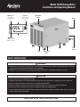
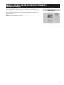
Aprilaire 1870F effectively removes moisture from the air, with a capacity of 130 pints per day. Ideal for spaces up to 3,000 sq ft, it features a washable MERV 8 filter to trap dust and allergens, and a built-in humidistat to maintain your desired humidity level between 40% and 80%. The digital control panel allows for easy operation and monitoring.
Aprilaire 1870F effectively removes moisture from the air, with a capacity of 130 pints per day. Ideal for spaces up to 3,000 sq ft, it features a washable MERV 8 filter to trap dust and allergens, and a built-in humidistat to maintain your desired humidity level between 40% and 80%. The digital control panel allows for easy operation and monitoring.


-
 1
1
-
 2
2
-
 3
3
-
 4
4
-
 5
5
-
 6
6
-
 7
7
-
 8
8
-
 9
9
-
 10
10
-
 11
11
-
 12
12


Aprilaire 1870F effectively removes moisture from the air, with a capacity of 130 pints per day. Ideal for spaces up to 3,000 sq ft, it features a washable MERV 8 filter to trap dust and allergens, and a built-in humidistat to maintain your desired humidity level between 40% and 80%. The digital control panel allows for easy operation and monitoring.
Ask a question and I''ll find the answer in the document
Finding information in a document is now easier with AI
Related papers
-
Aprilaire 1870F Owner's manual
-
Aprilaire 1820 Owner's manual
-
Aprilaire 1700FS Owner's manual
-
-
-
-
-
-
-
Other documents
-
Carrier DEHXXCDA1080-AO4 Cent Whole House 4 Pack Dehumidifier Owner's manual
-
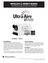 Therma-Stor Products Group XT150H User manual
-
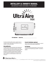 Therma-Stor Products Group 90H User manual
-
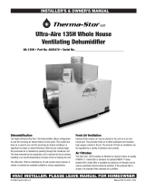 Therma-Stor Products Group UA-135H User manual
-
 DanVex DEH-1000wp User manual
-
EINHELL 23.691.11 Datasheet
-
 Therma-Stor Products Group UA-150H User manual
-
 Therma-Stor Products Group FOCUS 135H User manual
-
Johnson Controls S1-CVD090T01 User manual
-
TOOVEM Digital User manual


