Atlantis Land A05-17AM-D01, A05-17BM-D03, A05-19BM-D02 User manual
- Category
- TVs & monitors
- Type
- User manual
This manual is also suitable for

A05-17AM-D01 - A05-17BM-D03 – A05-19BM-D02_X02
A05-17AM-D01 A05-17BM-D03
A05-19BM-D02
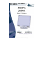
MONITOR LCD
MONITEUR LCD
User Manual
Manuale d’uso
Manuel d’utilisation
Page is loading ...

A05-17AM-D01 - A05-17BM-D03 - A05-19BM-D02_X02 3 - 40
ENGLISH
IMPORTANT SAFETY INSTRUCTIONS 2
1 GETTING STARTED 2
1.1 Precautions 2
1.2 Cleaning the TFT LCD Monitor 2
1.3 Federal Communications Commission (FCC) Statement 2
2 INSTALLING THE MONITOR 2
2.1 Unpacking 2
2.2 Installing the Base 2
2.3 Installing the Monitor 2
3 CONTROL FUNCTIONS 2
4 FUNCTION SELECT 2
4.1 Input Select (only for A05-17BM-D03) 2
4.2 Video 2
4.3 Audio 2
4.4 Color 2
4.5 Language 2
4.6 Tools 2
5 MICRO-CONTROLLER FEATURES 2
6 DISPLAY MODES MEMORY 2
6.1 User Setting Area 2
6.2 Factory Presetting Area 2
7 SIGNAL CONNECTOR PIN-OUTS 2
7.1 15-pin Mini D-type Male VGA Connector 2
8 POWER SAVING FEATURE 2
9 TIME SETTINGS 2
10 SPECIFICATIONS 2
ITALIANO
AVVERTENZE 2
11 PRIMA DI INIZIARE 2
11.1 Precauzioni 2
11.2 Pulizia del pannello LCD 2
11.3 Comunicato relativo alle interferenze Radio 2
11.4 Precauzioni per il cavo di alimentazione 2
12 INSTALLAZIONE DEL MONITOR 2
12.1 Disimballo 2
12.2 Installare la base 2
12.3 Installazione del monitor 2
13 FUNZIONI DI CONTROLLO 2
14 SELEZIONE DELLA FUNZIONE 2
14.1 Selezione ingresso (solo per A05-17BM-D03) 2
14.2 Video 2
14.3 Audio 2
14.4 Colore 2
14.5 Lingua 2
Page is loading ...

ENGLISH
A05-17AM-D01 - A05-17BM-D03 - A05-19BM-D02_X02 5 - 40
Important Safety Instructions
• Read the Safety Instructions carefully and keep it for later use.
• Be aware of all warnings and instruction signs marked on the products.
• When cleaning, turn off the electrical supply at all times. Never use liquid or aerosol detergent, use
a damp rag instead. For more details, please refer to Pag. 6 “Cleaning the Monitor.”
• Always keep the product away from heavy moisture.
• Keep this product stable all times. The product may fall causing serious damage.
• Do not clog apertures on the bezels used for ventilation purpose. Do not install this product in
poor ventilated areas. Always keep this product away from all kinds of heat sources.
• The power source used for this product must match one marked on the product's label. Please
consult your dealer if you have any doubt.
• In order to avoid electric shock, a 3-wire plug with a grounding pin is provided. Do not use any
kind of plug without grounding.
• Do not lay the power cord in a pathway or rest anything heavy on it.
• Do not insert objects or pour liquid into this product through apertures on bezels. It may touch a
high voltage area causing an electric shock or short circuit.
• Do not attempt to repair the product by yourself. It may expose you to electric shock. Contact a
dealer near you for service.
• Do not plug the power cord in under the following circumstances. A qualified field service
electrician is needed.
• When the power cord is damaged or frayed.
• If liquid has been poured into the product.
• If the product has been exposed to rain or heavy moisture.
• If the product can't be adjusted and operated properly by following the operative instructions. Intent
to do more advanced adjustments may result in extensive work for field service electrician.
• If the product has been dropped or the casting is broken.
• If there is a dramatic change of the performance.
• A proper type of power cord has been selected according to the safety of destination and must be
used to prevent electric shock.
1 Getting Started
Congratulations on your purchase of a TFT LCD Color Monitor. This section lists package contents,
features, precautions, as well as cleaning and installation instructions.
IMPORTANT! PLEASE KEEP THE ORIGINAL BOX AND ALL PACKING MATERIAL FOR FUTURE SHIPPING
NEEDS
.
1.1 Precautions
• Sit at least 18"(45 cm) away from the screen when in use.
• Do not touch the LCD panel with your bare hands. Oil from your skin is difficult to remove and
may damage the screen.
• Do not expose the LCD monitor directly under sunlight or other heat sources. When in use, the
LCD screen should be facing away from light sources to reduce glare.
• It is important to choose a well-ventilated area to place your LCD monitor for adequate ventilation.
Do not place anything on top of the LCD monitor.
• Ensure the area around the LCD monitor is clean and moisture-free.
• Do not place heavy objects on the power cord, adapter, or signal cables.
• If smoke, abnormal noise, or strange odor occurs, immediately turn the LCD monitor off and call
your dealer. Do not continue using the LCD monitor.
• Do not remove the rear cover by yourself. The display unit contains high-voltage parts and may
expose you to the electric shock. Contact your local dealer if service is needed.

ENGLISH
A05-17AM-D01 - A05-17BM-D03 - A05-19BM-D02_X02 6 - 40
• When moving, always handle your LCD monitor with care.
• Do not forcefully press down against the LCD display as this will damage the monitor.
1.2 Cleaning the TFT LCD Monitor
• Wipe the screen gently with a clean camel hairbrush, or a soft, clean, lint-free cloth.
Removing the dust and other particles will prevent your LCD panel from being scratched.
• Never pour or spray any liquid onto the LCD monitor
• Do not apply pressure to the LCD panel.
1.3 Federal Communications Commission (FCC)
Statement
This Equipment has been tested and found to comply with the limits for a class B digital device, pursuant to
Part 15 of the FCC rules. These limits are designed to provide reasonable protection against harmful
interference in a residential installation. This equipment generates, uses and can radiate radio frequency
energy and, if not installed and used in accordance with the instructions, may cause harmful interference to
radio communications. However, there is no guarantee that interference will not occur in a particular
installation. If this equipment does cause harmful interference to radio or television reception, which can be
determined by turning the equipment off and on, the user is encouraged to try to correct the interference by
one or more of the following measures:
• Reorient or relocate the receiving antenna.
• Increase the separation between the equipment and receiver.
• Connect the equipment into an outlet on a circuit different from that to which the receiver is
connected. - Consult the dealer or an experienced radio/TV technician for help.
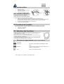
2 Installing the Monitor
2.1 Unpacking
Open the shipping cartons and check the contents.
If any items are missing or damaged, contact your dealer immediately.
The package should include the following items:
• TFT color monitor
• User's guide
• Power cord
• Signal cable
• DC power adapter
• Audio cable
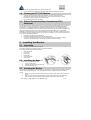
2.2 Installing the Base
Follow these steps to install the base:
1. Turn the monitor down.
2. Assembly the base to the arm with screw.
3. Tie the screw with a coin.
2.3 Installing the Monitor
This monitor is equipped with an auto sensing DC power adapter for voltage ranges 100-240VAC, 60/50Hz.
Confirm the line voltage designation on the rear panel of the monitor. Follow these steps to install the
monitor:
1. Before you connect the cables, made sure that the monitor and the system uni power switches
are off.
2. Plug one end of the 15pin-signal cable to the monitor and the other end to the video signal
connector at the rear of the system. Tighten the two screws on the cable connector.

ENGLISH
A05-17AM-D01 - A05-17BM-D03 - A05-19BM-D02_X02 7 - 40
3. Connect the DC power cord to the DC jack.
4. Connect the power cable.
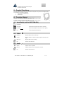
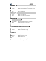
3 Control Functions
The monitor digital control functions are located on the front panel. They are shown in the figure below
and described in the following paragraphs.
1. Power Switch with Indicator LED
2. Function Keys
4 Function Select
With the U and V knobs, you can adjust the speakers volume.
Press the 1 knob to show the OSD menu. Than use the U and V knobs to select
a function. Press the 2 knob to close the OSD menu. You can hold the 2 knob for
more than 3 second to adjust the image quality automatically.
4.1 Input Select (not for A05-17AM-D01)
Input Select
VGA signal Select the image signal coming from the VGA cable.
DVI signal Select the image signal coming from DVI cable. (option)
Exit Close the Signal Select OSD menu.
4.2 Video
Brightness Adjust the luminance level in the image.
Contrast Adjust the difference in luminance between light and dark areas of the
image.
Black Level Adjust the black Level in the image.
Exit Close the Video OSD menu.
4.3 Audio
Volume Adjust the volume of speakers
Balance Adjust the speaker’s volume to right side or left side.
Exit Close the Audio OSD menu

ENGLISH
A05-17AM-D01 - A05-17BM-D03 - A05-19BM-D02_X02 8 - 40
4.4 Color
4.4.1 Color Temperature
User Adjust the R.G.B. gain level.
6500K Select color temperature to 6500°K.
9300K Select color temperature to 9300°K.
Exit Close the Color Temperature OSD menu.
4.4.2 Adjust the flesh tone of the image
Shade Adjust the shade of the image color.
Saturation Adjust the saturation of the image color.
Exit Close the Color OSD menu.
4.4.3 Image Adjust
Geometry Adjust geometry of the image automatically.
Horizontal size Adjust the horizontal sync size of signal.
Horizontal phase Adjust the horizontal sync phase of signal.
Horizontal position Adjust the horizontal position of the image.
Vertical position Adjust the vertical position of the image.
Exit Close the Image OSD menu
4.5 Language
Sets the language of the OSD windows.
4.6 Tools
4.6.1 OSD Controls
Display time Setting the OSD menu display time.
OSD H. Position OSD H. Position Adjust the horizontal position of the OSD menu.
OSD V. Position OSD V. Position Adjust the vertical position of the OSD menu.
Exit Close the OSD Control OSD menu

ENGLISH
A05-17AM-D01 - A05-17BM-D03 - A05-19BM-D02_X02 9 - 40
4.6.2 Recall the factory default setting
4.6.3 Sharpness
Adjust the picture display more clear
Exit Close the Tools OSD menu
Exit Close the OSD menu
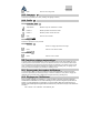
5 Micro-controller Features
The micro-controller automatically detects the video board installed in your system. When you turn on the
monitor, the micro-controller first checks the display mode memory stored in the user setting area of the
video board, and then the factory presetting area. It then adjusts to the proper display mode.
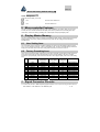
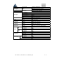
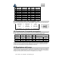
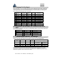
6 Display Modes Memory
The micro-controller has the memory capacity to store different display modes, including timing formats and
display-settings. This memory capacity is divided into two parts: the user setting area and the factory
presetting area.
6.1 User Setting Area
The user setting area on the micro-controller maintains in its memory the last display modes set by the
user. You can change the settings, or add a nonstandard mode. The micro-controller always detects and
displays the last mode stored in the user setting area first when the monitor is turned on.
6.2 Factory Presetting Area
There are some preferred display modes preset in the micro-controller. These display modes are preset
at the factory and include the most popular display modes currently available. The micro-controller
searches for a proper display mode in this area if it fails to find a proper display mode in the user setting
area.
MODE
Resolution
(Dots*lines)
Horizontal
Freq. (KHz)
Vertical
Freq. (Hz)
Remark
1. VGA 640×350 31.5 70 Non-interlaced
2. VGA 720×400 31.5 70 Non-interlaced
3. VGA 640×480 31.5 60 Non-interlaced
4. VESA/75 640×480 37.5 75 Non-interlaced
5. VESA/60 800×600 37.9 60 Non-interlaced
6. VESA/75 800×600 46.9 75 Non-interlaced
7. VESA/60 1024×768 48.4 60 Non-interlaced
8. VESA/70 1024×768 56.5 70 Non-interlaced
9. VESA/75 1024×768 60.0 75 Non-interlaced
10. VESA/60 1280×1024 64.0 60 Non-interlaced
11. VESA/75 1280×1024 80.0 75 Non-interlaced
7 Signal Connector Pin-outs
To connect VGA, 8514A or IBM-compatible graphics adapters, use a 15 pin mini D-type male connector.

ENGLISH
A05-17AM-D01 - A05-17BM-D03 - A05-19BM-D02_X02 10 - 40
7.1 15-pin Mini D-type Male VGA Connector
1 Red Video 6 Red Ground 11 Ground
2 Green Video 7 Green Ground 12 Serial Data/I/O
3 Blue Video 8 Blue Ground 13 H. Sync
4 Ground 9 No Connection 14 V. Sync
5
No Connection
10
Sync Ground
15
Serial Clock Input
8 Power Saving Feature
When the power saving active them the power indicator LED will be from Green Light to Amber, And
power saving feature complies with these VESA power saving modes:
Mode H. Sync. V. Sync. LED
Power Consumption
Normal On On Green
<40W
A05-17AM-D01
A05-17BM.D03
<45W
A05-19BM-D02
Stand-by Off On Amber < 3W
Suspend On Off Amber < 3W
Off Off Off Amber < 3W
The monitor uses the H. Sync and V. Sync signals to determine the operation mode to enter.
The monitor power-saving feature automatically turns off H. Sync and V. Sync if there is no input from the
system for a certain period of time. To use this feature, you need a green PC that is compliant with the
VESA power saving feature or a software utility to detect system input such as keyboard or mouse.
9 Time Settings
Time settings are adjusted from the system unit by software. To fulfill the requirements in the NUTEK
specification 803299/94 the total time from indicated inactivity to Power Saving position A2 (VESA OFF)
must not be set more than 70 minutes. We recommend you switch off the monitor when you do not intend to
use it for awhile.
10 Specifications
A05-17AM-D01
A05-17BM.D03
17.0" (full 17.0" viewable diagonal area)
Size
A05-19BM-D02
19.0" (full 17.0" viewable diagonal area)
Type TFT (Thin Film Transistor), Active Matrix Panel
Pixel Pitch
A05-17AM-D01
A05-17BM.D03
0,264mm
A05-19BM-D02
0,294mm
Color 16.7M
Glass surface Anti-Glare & Hard Coat 3H
Brightness 250 cd/m
2
A05-17AM-D01
A05-17BM.D03
500:1
Contrast
A05-19BM-D02
600:1
View Angle 170 H - 170 V
A05-17AM-D01
A05-17BM.D03
337.92x270.336 mm
LCD
Full screen
A05-19BM-D02
376.320X301.056 mm

ENGLISH
A05-17AM-D01 - A05-17BM-D03 - A05-19BM-D02_X02 11 - 40
Resolution Primary Mode 1280x1024 @75Hz (Max.)
RGB Analog
Input Signal Video
DVI Digital (not for A05-17AM-D03)
Connectors D-sub 15 pin
Input Signal
DVI-D (not for A05-17AM-D03)
Sync H. V., Separate Sync,
TTL Compatible
Horizontal Frequency 31-80kHz,
Vertical Frequency 50-75Hz,
Video Sync
Video Bandwidth 80MHz
Input Stereo mini- Audio Line-in
Audio
Speakers 3W x 2 (At 1KHz for THD 1% Amplifier)
Power Voltage 220V - 12V / 4.2A
Temperature 0°C to 40°C
Operating
Conditions
Humidity 10-90% (non-condensing)
Temperature 0 to 60 Storage
Conditions
Humidity 10-90% (non-condensing)
Physical 425mm (L) x 175mm (W) x 425mm (H)
Dimensions
Package 490mm (L) x 155mm (W) x 500mm (H)mm
A05-17AM-D01
A05-17BM.D03
5.5 Kg
Net
A05-19BM-D02
6,0 Kg
A05-17AM-D01
A05-17BM.D03
7.0 Kg
Weight
Gross
A05-19BM-D02
7,5 Kg
Safety UL/CUL, TUV/GS, CE, CB, FCC-B
Energy Star EPA
Regulations
Quality ISO 13404-2 Class II
A05-17AM-D01
A05-17BM.D03
<42W
On
A05-19BM-D02
<45W
Power saving
Off <3W
Page is loading ...
Page is loading ...
Page is loading ...
Page is loading ...
Page is loading ...
Page is loading ...
Page is loading ...

ITALIANO
A05-17AM-D01 - A05-17BM-D03 – A05-19BM-D02_X02
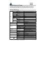
20 Specifiche
A05-17AM-D01
A05-17BM.D03
17.0" (full 17.0" viewable diagonal area)
Dimensioni
A05-19BM-D02
19.0" (full 17.0" viewable diagonal area)
Tipo TFT (Thin Film Transistor), Active Matrix Panel
A05-17AM-D01
A05-17BM.D03
0,264mm
Pixel Pitch
A05-19BM-D02
0,294mm
Colori 16.7M
Trattamento superficie Anti-Glare & Hard Coat 3H
Luminosità 250 cd/m
2
A05-17AM-D01
A05-17BM.D03
500:1
Contrasto
A05-19BM-D02
600:1
Angolo Visuale 170 H - 170 V
A05-17AM-D01
A05-17BM.D03
337.92x270.336
LCD
Area Visibile
A05-19BM-D02
376.320X301.056 mm
Risoluzione Primaria 1280x1024 @75Hz (Max.)
RGB Analogico
Segnale ingresso Video
DVI Digitale (non per A05-17AM-D01)
Sync H. V., Separate Sync,
TTL Compatibile
Frequenza Orizzontale 31-80kHz,
Frequenza Verticale 50-75Hz,
Video Sync
Banda Passante 80MHz
D-sub 15 pin
Connettore Input Signal
DVI-D (non per A05-17AM-D01)
Input Stereo mini- Audio Line-in
Audio
Altoparlanti 3W x 2 (At 1KHz for THD 1% Amplifier)
Alimentazione 220 V 12V / 4.2A
Temperatura 0°C to 40°C
Condizioni di utilizzo
Umidità 10-90% (senza condensa)
Temperatura 0 a 60
Condizioni di imballo
Umidità 10-90% (senza condensa)
Prodotto 425mm (L) x 175mm (W) x 425mm (H)
Dimensioni
Imballo 490mm (L) x 155mm (W) x 500mm (H)mm
A05-17AM-D01
A05-17BM.D03
5.5Kgs
Netto:
A05-19BM-D02
6,0 Kg
A05-17AM-D01
A05-17BM.D03
7.0Kg
Peso
Lordo:
A05-19BM-D02
7,5 Kg
Sicurezza UL/CUL, TUV/GS, CE, CB, FCC-B
Energy Star EPA
Normative
Qualità ISO 13404-2 Class II
Page is loading ...
Page is loading ...
Page is loading ...
Page is loading ...
Page is loading ...
Page is loading ...
Page is loading ...
Page is loading ...

FRANCAIS
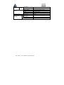
A05-17AM-D01 - A05-17BM-D03 – A05-19BM-D02_X02
A05-17AM-D01
A05-17BM.D03
7.0 Kg
Emballé
A05-19BM-D02
7,5 Kg
Sécurité (Safety) UL/CUL, TUV/GS, CE, CB, FCC-B
Energy Star EPA
Qualité ISO 13404-2 Class II
Normes
Panneau LCD Grade A+
Eclairage arrière Durée de vie 50.000 H
A05-17AM-D01
A05-17BM.D03
<42W
A05-19BM-D02
<45W
Economiseurs
d'énergie
En fonctionnement <3W

A05-17AM-D01 - A05-17BM-D03 – A05-19BM-D02_X02
WARRANTY CERTIFICATE
CONDIZIONI DI GARANZIA
CERTIFICAT DE GARANTIE
Page is loading ...

A05-17AM-D01 - A05-17BM-D03 – A05-19BM-D02_X02
WARRANTY CERTIFICATE
We thank You for your decision to have bought an ATLANTIS LAND® product.
Our society, thank to the quality of its products, offers You an extended guarantee lasting 36 months, both
if the product serves for a private use and if it works for a professional one.
This service will be provided to you directly by ATLANTIS LAND®, without asking you for more
interventions, for example brought off by your usual retailer or by others operators.
However please read carefully all guarantee clauses, in order to avoid ungrateful mistakes for the future
eventualities.
If you will provide within 15 days from the purchase to register it on the ATLANTIS LAND® web
site www.atlantis-land.com ,you won’t be asked, if you will need an intervention, the original proof of
purchase (see clause n° 6).
Clauses
1. The product is warranted for a period of 36 months from the date of purchase.
2. During this period ATLANTIS LAND® will replace the apparatus which will show defects in
conformity to that product’s standard.
3. The replacement will take place without any cost for the costumer.
4. To start the guarantee process the costumer will have to report the defect (by Fax, E-Mail or
Telephone) to the ATLANTIS LAND® Assistance Service, that will provide a new RMA
number after checking the out of order product.
5. This RMA number will have to be reported, together with all the other information
requested, on the appropriate form, attached to the product or available on the web site
www.atlantis-land.com (Support\Warranty page)
6. This form must be accompanied by a valid proof of purchase (Sale receipt or Invoice ), this
clause is not compulsory if the costumer had previously registered his purchase on the
ATLANTIS LAND® web site.
7. The non conformity to one of the previous points 5 and 6 makes the Guarantee
irrecoverable by the costumer.
8. The product must be returned with its original package intact and complete with all its
accessories.
9. If you return a non original or non intact package the material will travel at your own risk ,
and ATLANTIS LAND® doesn’t assume any kind of responsibility about eventual damages
even in case of a transport by ATLANTIS LAND® itself .
10. ATLANTIS LAND® takes back the defective product and replace it with the expedition to
the costumer of a new one.
11. Every ATLANTIS LAND® product is identified by a serial number (S/N) , the cancellation,
even partial, of it bring to the cancellation of the Guarantee.
12. The Guarantee is ineffective even when the damages are due to clear fraud, negligence,
the non conformity with the specifics of the product, modification or tampering.
13. The Guarantee is ineffective also if we find out attempts, succeeded or not, of opening the
apparatus.
14. Moreover damages due to natural phenomena or to extraordinary happenings they are not
included in the Guarantee.
15. Damages due to the connections of the apparatus to tensions which are different from the
ones indicated, or due to sudden changes in the tension of the net to which the apparatus
is connected to, as well as the ones due to any kind of electrical discharge (lightning,
overextensions, electrostatic or inductive discharges ) are not included too.
16. At last damages due to fire or liquid infiltrations are excluded as well.
17. All the elements that undergo wear and tear as accumulator’s batteries , batteries
themselves , fuses and bulbs even when furnished , cables for the connection or the
feeding and connectors are not included in the Guarantee.
18. Exactly only for the line of UPS products the batteries that are furnished with the
product itself are in Guarantee for 12 months.
19. The external feeders, of every kind of apparatus, are covered by a 12months
Guarantee.

A05-17AM-D01 - A05-17BM-D03 – A05-19BM-D02_X02
20. Possible updating of the software or of the firmware, revisions, settings or upkeeps are not
covered by the Guarantee too.
21. For each apparatus send for reparation and for which no defects will be found by the
Assistance Service, you will have to pay for the transport (retire and return) and for a
contribution of test that amount to €30. The total sum will be notified to you by ATLANTIS
LAND®, and only the payment through an allowance will make the return of the apparatus
possible.
22. If after 6 months from the request we haven’t received the payment yet
ATLANTIS LAND® will proceed with the selling off of the apparatus without need to inform
you of anything and it will consider the practice as closed.
23. The Guarantee is provided only by ATLANTIS LAND® s.p.a. to its Assistance Center
.Address : Via De Gasperi, 122 – 20017 – Mazzo di Rho (MI) – Phone: 02-93907634.
24. Any controversy will be up to the Foro di Milano.
Page is loading ...
Page is loading ...
Page is loading ...
Page is loading ...

WARRANTY CLAIM FORM
Model
Serial Number
Family Name
Name
Company
Address
Post Code Town Country
Tel
Fax
e-mail
Date of Purchase
FAULT DESCRIPTION
Dealer Stamp
Complete and fax this WARRANTY CLAIM together with the purchase bill to obtain
Page is loading ...
Page is loading ...

HEADQUARTER & EUROPE
A
TLANTIS LAND S.p.A.
Viale De Gasperi, 122
Mazzo di Rho – MI – Italy
info@atlantis-land.com
A
TLANTIS LAND FRANCE
C
ENTRE AMSTERDAM
7,
RUE D’AMSTERDAM
P
ARIS – FRANCE
info.fr@atlantis-land.com
FAR EAST AND USA SALES:
Atlantis Land
International Sales Office
N° 249 Hsing South Rd.
Taipei – Taiwan
Atlantis Land Technology L.t.d.
3
rd
. Floor, Jonsim Palace
228 Queen’s Road East
Wanchai, Hong Kong
info.hk@atlantis-land.com
-
 1
1
-
 2
2
-
 3
3
-
 4
4
-
 5
5
-
 6
6
-
 7
7
-
 8
8
-
 9
9
-
 10
10
-
 11
11
-
 12
12
-
 13
13
-
 14
14
-
 15
15
-
 16
16
-
 17
17
-
 18
18
-
 19
19
-
 20
20
-
 21
21
-
 22
22
-
 23
23
-
 24
24
-
 25
25
-
 26
26
-
 27
27
-
 28
28
-
 29
29
-
 30
30
-
 31
31
-
 32
32
-
 33
33
-
 34
34
-
 35
35
-
 36
36
-
 37
37
-
 38
38
-
 39
39
-
 40
40


Atlantis Land A05-17AM-D01, A05-17BM-D03, A05-19BM-D02 User manual
- Category
- TVs & monitors
- Type
- User manual
- This manual is also suitable for
Ask a question and I''ll find the answer in the document
Finding information in a document is now easier with AI
in other languages
Related papers
-
 Atlantis Land A04-MO2301 User manual
-
 Atlantis Land A04-MO2313 User manual
-
 Atlantis Land A04-MO2313 User manual
-
 Atlantis Land A04-MO2454 User manual
-
Atlantis AO2-F5P User manual
-
 Atlantis Land A04-W2202 User manual
-
 Atlantis Land A04-MB1001 User manual
-
 Atlantis Land A04-W1102 User manual
-
-


