Page is loading ...

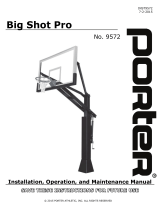
INSTALLATION INSTRUCTIONS
O
UTDOOR
B
ACKSTOP WITH
S
INGLE
4'-0" E
XTENS
UU
ION
No. 00164-_ _ _
O
UTDOOR
B
ACKSTOP WITH
D
OUBLE
4'-0" E
XTENSION
No. 00184-_ _ _
WARNING
READ ALL INSTRUCTIONS THOROUGHLY BEFORE ATTEMPTING TO INSTALL THIS EQUIPMENT.
INSTALLATION / ASSEMBLY OF THIS EQUIPMENT MUST BE DONE ONLY BY ADULTS, WHO ARE PHYSICALLY
CAPABLE OF DOING SO.
INSTALLER NOTE:
Upon completion of the installation/assembly of this backstop, make sure
this instruction manual is in the possession of the owner or facility
manager, to save for future reference, and to order replacement parts.
INST 00367 112
¤ 2010 PORTER ATHLETIC EQUIPMENT COMPANY. ALL RIGHTS RESERVED. 8-1-2010

WARNING
READ ALL WARNINGS THOROUGHLY BEFORE USING THIS EQUIPMENT.
FAILURE TO COMPLY WITH THE FOLLOWING INSTRUCTIONS AND WARNINGS MAY RESULT IN SERIOUS
INJURIES AND/OR PROPERTY DAMAGE.
xDO NOT HANG on the rim or any part of system, including backboard, support braces or net.
xDuring play, especially when performing dunk-type activities, keep player's face away from the backboard, rim and net.
Serious injuries could occur if teeth/face come in contact with backboard, rim or net. All players must wear a mouth guard
when performing dunk-type activities.
xDo not slide, climb or play on pole.
xDuring play, do not wear jewelry (rings, watches, necklaces, etc.). These objects may entangle in net.
xKeep organic material away from base of post. Grass, litter, etc. could cause corrosion and/or deterioration.
xCheck post system for signs of corrosion (rust, pitting, chipping, etc.) and repaint with exterior enamel paint. If rust has
penetrated through the steel anywhere, replace post immediately.
xCheck system before each use for loose hardware, excessive wear, and signs of corrosion, and repair before use.
xCheck system before each use for instability.
xNever allow play on damaged equipment.
THE OWNER OF THIS EQUIPMENT IS RESPONSIBLE TO ENSURE THAT ALL INDIVIDUALS FOLLOW THESE
SAFETY AND OPERATING INSTRUCTIONS TO AVOID INJURIES OR PROPERTY DAMAGE. PROPER USE AND
SUPERVISION OF THIS EQUIPMENT IS ESSENTIAL TO HELP REDUCE THE POSSIBILITY OF ACCIDENTS OR
INJURIES.
NOTE
These instructions detail installing a No. 164 or 184 Backstop permanently in a concrete footing. If using a No. 164 or 184
Backstop with an outdoor ground sleeve, consult factory for information on special post. DO NOT PROCEED.
2

3
PARTS LIST
PARTS LIST – No. 164 BACKSTOP WITH 4-1/2" DIAMETER POST AND SINGLE 4'-0" EXTENSION
No. 164 BACKSTOP With FAN BACKBOARD No. 164 BACKSTOP With RECTANGULAR BACKBOARD
Item No. Qty. Part Number Description Item No. Qty. Part Number Description
1 1 Fan Backboard
2 1 Goal
3 1 UPRT 00258 0G0 Post
4 1 EXTN 00050 009 Extension Arm
7 1 PCAP 00027 002 Pipe Cap
14 2 UBOT 00011 0E0 5/8" U-Bolt (For 4-1/2” Dia. Pole)
15 4 HDWE 04006 0E0 5/8" Lock washer
16 4 HDWE 03012 0E0 5/8" Hex Nut
1 1 Rectangular Backboard
2 1 Goal
3 1 UPRT 00258 0G0 Post
4 1 EXTN 00050 009 Extension Arm
5 2 SWAY 00175 0G0 Brace Tube
6 1 CLMP 000830G0 Clamping Band
7 1 PCAP 00027002 Pipe Cap
8F 2 BRCE 000210G0 Brace Clamp (#216 only)
9F 6 HDWE 01124 0E0 3/8" x 1" Lg. Hex Head Cap Screw i
10 1 HDWE 01125 0E0 3/8" x 1-1/4" Lg. Hex Head Cap Screw i
11F 2 HDWE 012070E0 3/8” x 2-1/4” Lg. Hex Head Cap Screw i
12 7 HDWE 04002 0E0 3/8" Lock washer
13 7 HDWE 03002 0E0 3/8" Hex Nut
14 2 UBOT 00011 0E0 5/8" U-Bolt (For 4-1/2” Dia. Pole)
15 4 HDWE 04006 0E0 5/8" Lock washer
16 4 HDWE 03012 0E0 5/8" Hex Nut
18G 2 HDWE 012060E0 3/8” x 2” Hex Head Cap Screw
19 4 HDWE 050040E0 3/8” Flat Washer
F – Rect. Fiberglass Backboard Only G – Rect. Glass Backboard Only
i NOTE – Grade 5 Hardware
PARTS LIST – No. 184 BACKSTOP WITH 4-1/2" DIAMETER POST AND DOUBLE 4'-0" EXTENSION
No. 184 BACKSTOP With FAN BACKBOARD No. 184 BACKSTOP With RECTANGULAR BACKBOARD
Item No. Qty. Part Number Description Item No. Qty. Part Number Description
1 2 Fan Backboard
2 2 Goal
3 1 UPRT 00258 0G0 Post
4 2 EXTN 00050 009 Extension Arm
7 2 PCAP 00027 002 Pipe Cap
15 4 HDWE 04006 0E0 5/8" Lock washer
16 4 HDWE 03012 0E0 5/8" Hex Nut
17 4 HDWE 01276 0E0 5/8" x 7-1/2" Lg. Hex Head Cap Screw
Grade 8
1 2 Rectangular Backboard
2 2 Goal
3 1 UPRT 00258 0G0 Post
4 2 EXTN 00050 009 Extension Arm
5 4 SWAY 00175 0G0 Brace Tube
6 2 CLMP 000830G0 Clamping Band
7 1 PCAP 00027002 Pipe Cap
8F 4 BRCE 000210G0 Brace Clamp (#216 only)
9F 12 HDWE 01124 0E0 3/8" x 1" Lg. Hex Head Cap Screw i
10 2 HDWE 01125 0E0 3/8" x 1-1/4" Lg. Hex Head Cap Screw i
11F 4 HDWE 012070E0 3/8” x 2-1/4” Lg. Hex Head Cap Screw i
12 12 HDWE 04002 0E0 3/8" Lock washer
13 4 HDWE 03002 0E0 3/8" Hex Nut
15 4 HDWE 04006 0E0 5/8" Lock washer
16 4 HDWE 03012 0E0 5/8" Hex Nut
17 4 HDWE 01276 0E0 5/8" x 7-1/2" Lg. Hex Head Cap Screw
Grade 8
18G 4 HDWE050040E0 3/8” x 2” Hex Head Cap Screw
19 8 HDWE 050040E0 3/8” Flat Washer
F – Rect. Fiberglass Backboard Only G – Rect. Glass Backboard Only
i NOTE – Grade 5 Hardware

1. Check all items against Parts List on Page 3 to ensure all parts and hardware are available to complete the installation.
INSTALL POST
2. Locate center position of post. CAUTION – Contact your local utility companies to locate buried electrical, gas, water lines, etc.
BEFORE DIGGING HOLE FOR FOOTING. Also, check for overhead utilities.
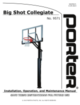
3. Dig a footing 3'-0" in diameter by 4'-0" in depth, centered on the final location of the post. NOTE – Footing size may have to be
increased depending on soil conditions. See Detail "A".
4. Using at least two adults, tip the bottom end of the post (with anchor lugs) into the footing hole, and raise it to the vertical
position. See Detail "A". Brace the post with 2x4's as required, to ensure the post remains plumb and at the proper height above
the playing surface.
5. Center the post in the hole, and brace as required to support it
while the concrete sets up. NOTE – The top of the post will be
located 12' 11-3/4" above the playing surface. See Detail "A".
6. Pour concrete into the hole (approximately 1.1 cubic yards),
tamping as it is poured to eliminate air pockets. Slope top of
footing upward toward post so that top of footing at post is
approximately 1/2" above playing surface. Slope footing away
from post, to a point that is 3" below the playing surface. See
Detail "B". This will ensure proper drainage, reducing the
possibility of corrosion of the steel post. Do not cover the
footing at the post with dirt, sod or anything else that could
hold moisture.
Detail "B"
3"
12"
PLAYING
SURFACE
7. While concrete is still wet, use a level on two sides of the post to ensure it is plumb.
8. Allow concrete to cure at least 24 hours before proceeding.
4

ASSEMBLE EXTENSION ARM AND BRACES TO POST
9. This step requires three adults. Assemble extension arm(s) to post, using hardware as indicated below. The centerline of the
extension arm(s) must be located 9' 8-1/2" above playing surface. This will locate extension arm at the proper height, ensuring a
10'-0" goal height after assembly is completed. ¾ See Detail "C".
No. 164 With Single Extension Arm – Assemble extension arm to post using two u-bolts (14), 5/8" lock washers (15) and
5/8" hex nuts (16).
No. 184 With Double Extension Arms – Assemble extension arms to post using four 5/8" x 7-1/2" lg. hex head cap screws
(17), 5/8" lock washers (15) and 5/8" hex nuts (16).
¾A goal height lower than 10'-0" can be obtained by mounting the extension arm(s) at a lower height on the post (by
decreasing the 9' 8-1/2" dimension).
ASSEMBLE BACKBOARD AND GOAL
10. Assemble backboard and goal to extension arm using the four bolts furnished with the goal. Lay a level horizontally across the
top of the backboard and across the goal. Rotate backboard and goal as required until both are level. When level, tighten
hardware securely. Refer to specific instructions provided with each model of backboard and goal.
5

ASSEMBLE BACKBOARD BRACE TUBES
(NOT REQUIRED FOR FAN BACKBOARDS)
11. If installing a #216 Rectangular Fiberglass Backboard, install two brace clamps (6) as shown in the bottom half of Detail “D”.
Use 3/8" x 1" lg. hex head cap screws (10) and 3/8" lock washers (12) to secure the brace clamps to the back of the backboard.
12. Open up clamping band (6) and install around the offset tube as shown in Detail "D". Long nose vice-grip pliers will help to hold
clamp closed during assembly.
6

13. Loosely assemble front end of brace tubes (5) to backboard.
Rect. Glass Backboards – 3/8" x 2” hex head cap screws (18G), 3/8” flat washers (19), 3/8" lock washers (12) and 3/8" hex
nuts (13).
Rect. Fiberglass Backboards – Use 3/8" x 1" hex head cap screws (9F), 3/8” flat washers (19), 3/8" lock washers (12) and
3/8" hex nuts (13).
14. Loosely assembly back end of brace tubes to clamping bands (6), using 3/8" x 1-1/4" lg. hex head cap screw (11), 3/8" lock
washer (12) and 3/8" hex nut (13), See Detail "D". Brace tube ends fit between the clamping band ends. Use long nose vice-grip
pliers to hold clamping band ends together when installing cap screw.
15. Tighten all hardware from Steps No. 13 and 14.
16. IMPORTANT – Install pipe cap (7) on top of post. Failure to do so will allow water inside post, causing corrosion of the post,
and structural damage to the post during freezing conditions. See Detail "E".
17. NOTE – If additional stability is required from backstop, the post can be filled with concrete. NOTE – Be sure to reinstall the
pipe cap after concrete is poured.
18. Installation/assembly of backstop is now complete. Install optional post and/or backboard padding as required.
7
www.porterathletic.com
(888) 277-7778
THIS WARNING IS GIVEN IN COMPLIANCE
WITH CALIFORNIA’S PROPOSITION 65:
WARNING
This product contains chemicals known to the
State of California to cause cancer, birth defects
or other reproductive harm.
SAVE THESE INSTRUCTIONS FOR FUTURE USE
WARNING: This product can expose you to Titanium Dioxide,
which is known to the State of California to cause cancer.
For more information go to www.p65warnings.ca.gov.
E
/