1U Rackmount Server
User Guide
RS300-E11 Series

ii
Copyright © 2022 ASUSTeK COMPUTER INC. All Rights Reserved.
No part of this manual, including the products and software described in it, may be reproduced, transmitted,
transcribed, stored in a retrieval system, or translated into any language in any form or by any means,
except documentation kept by the purchaser for backup purposes, without the express written permission
of ASUSTeK COMPUTER INC. (“ASUS”).
ASUS provides this manual “as is” without warranty of any kind, either express or implied, including but not
limited to the implied warranties or conditions of merchantability or fitness for a particular purpose. In no
event shall ASUS, its directors, officers, employees, or agents be liable for any indirect, special, incidental,
or consequential damages (including damages for loss of profits, loss of business, loss of use or data,
interruption of business and the like), even if ASUS has been advised of the possibility of such damages
arising from any defect or error in this manual or product.
Specifications and information contained in this manual are furnished for informational use only, and are
subject to change at any time without notice, and should not be construed as a commitment by ASUS.
ASUS assumes no responsibility or liability for any errors or inaccuracies that may appear in this manual,
including the products and software described in it.
Product warranty or service will not be extended if: (1) the product is repaired, modified or altered, unless
such repair, modification of alteration is authorized in writing by ASUS; or (2) the serial number of the
product is defaced or missing.
Products and corporate names appearing in this manual may or may not be registered trademarks or
copyrights of their respective companies, and are used only for identification or explanation and to the
owners’ benefit, without intent to infringe.
E20157
Revised Edition V2
April 2022

iii
Contents
Safety information ..................................................................................................... vii
About this guide ......................................................................................................... ix
Chapter 1: Product Introduction
1.1 System package contents ......................................................................... 1-2
1.2 Serial number label .................................................................................... 1-3
1.3 System specifications ...............................................................................1-4
1.4 Front panel features ...................................................................................1-7
1.5 Rear panel features ....................................................................................1-7
1.6 Internal features .........................................................................................1-9
1.7 LED information .......................................................................................1-11
1.7.1 Front panel LEDs ...................................................................... 1-11
1.7.2 Storage device status LED........................................................ 1-12
1.7.3 LAN (RJ-45) LEDs .................................................................... 1-12
1.7.4 Rear panel LEDs ....................................................................... 1-13
1.7.5 Q-Code table ............................................................................. 1-14
Chapter 2: Hardware Information
2.1 Chassis cover .............................................................................................2-2
2.1.1 Removing the rear cover ............................................................. 2-2
2.2 Central Processing Unit (CPU) .................................................................2-3
2.2.1 Installing the CPU and heatsink .................................................. 2-3
2.3 System memory .........................................................................................2-8
2.3.1 Overview ..................................................................................... 2-8
2.3.2 Memory Configurations ............................................................... 2-8
2.3.3 Installing a DIMM ........................................................................ 2-9
2.3.4 Removing a DIMM ...................................................................... 2-9
2.4 Storage devices........................................................................................2-10
2.4.1 Installing a 3.5” storage device ................................................. 2-10
2.4.2 Installing a 2.5” storage device ................................................. 2-12
2.5 Expansion slot ..........................................................................................2-14
2.5.1 Installing an expansion card to the PCIe x16 slot on the
butterfly riser card bracket......................................................... 2-15
2.5.2 Installing an expansion card to the PCIe x8 slot on the
butterfly riser card bracket......................................................... 2-18
2.5.3 (optional) Installing an Intel® X710 10G LAN card to the
onboard PCIe slot ..................................................................... 2-21
2.5.4 Installing an M.2 module ........................................................... 2-24

iv
Contents
2.5.5 Installing the Baseboard Management Card ............................. 2-26
2.5.6 (optional) Installing the PFR module ......................................... 2-28
2.5.7 Configuring an expansion card ................................................. 2-29
2.6 Cable connections ...................................................................................2-30
2.7 Removable/optional components ...........................................................2-31
2.7.1 Redundant power supply module (on selected models) ........... 2-31
Chapter 3: Installation Options
3.1 Tool-less Friction Rail Kit ..........................................................................3-2
3.1.1 Installing the tool-less rack rail .................................................... 3-2
3.1.2 Rail kit dimensions ...................................................................... 3-4
3.2 Ball bearing Rail Kit ...................................................................................3-5
3.2.1 Attaching the rack rails ............................................................... 3-6
3.3 Cable management arm (optional for 1200 mm rack rails) ..................3-11
3.3.1 Attaching the cable management arm ...................................... 3-11
Chapter 4: Motherboard Information
4.1 Motherboard layout ....................................................................................4-2
4.2 Jumpers ......................................................................................................4-5
4.3 Onboard LEDs .......................................................................................... 4-11
4.4 Internal connectors ..................................................................................4-13
Chapter 5: BIOS Setup
5.1 Managing and updating your BIOS ..........................................................5-2
5.1.1 ASUS CrashFree BIOS 3 utility................................................... 5-2
5.1.2 ASUS EzFlash Utility................................................................... 5-3
5.1.3 BUPDATER utility ....................................................................... 5-4
5.2 BIOS setup program ..................................................................................5-6
5.2.1 BIOS menu screen ...................................................................... 5-7
5.2.2 Menu bar ..................................................................................... 5-7
5.2.3 Menu items..................................................................................5-8
5.2.4 Submenu items ........................................................................... 5-8
5.2.5 Navigation keys ........................................................................... 5-8
5.2.6 General help................................................................................5-8
5.2.7 Configuration fields ..................................................................... 5-8
5.2.8 Pop-up window............................................................................5-8
5.2.9 Scroll bar ..................................................................................... 5-8
5.3 Main menu ..................................................................................................5-9

v
Contents
5.3.1 System Language [English] ........................................................ 5-9
5.3.2 System Date [Day xx/xx/xxxx] ..................................................... 5-9
5.3.3 System Time [xx:xx:xx] ............................................................... 5-9
5.4 Advanced menu .......................................................................................5-10
5.4.1 CPU Configuration .................................................................... 5-11
5.4.2 Power & Performance ............................................................... 5-12
5.4.3 Server ME Configuration ........................................................... 5-15
5.4.4 System Event Log ..................................................................... 5-16
5.4.5 Trusted Computing.................................................................... 5-17
5.4.6 Redfish Host Interface Settings................................................. 5-18
5.4.7 Onboard LAN Configuration ...................................................... 5-18
5.4.8 Serial Port Console Redirection ................................................ 5-19
5.4.9 Intel TXT Information.................................................................5-22
5.4.10 SIO Configuration......................................................................5-22
5.4.11 PCI Subsystem Settings ........................................................... 5-23
5.4.12 USB Configuration .................................................................... 5-27
5.4.13 Network Stack Configuration..................................................... 5-28
5.4.14 CSM (Compatibility Support Module) ........................................ 5-29
5.4.15 NVMe Configuration .................................................................. 5-31
5.4.16 APM Configuration .................................................................... 5-31
5.4.17 Third-party UEFI driver configurations ...................................... 5-32
5.5 Chipset menu ...........................................................................................5-33
5.5.1 System Agent (SA) Configuration ............................................. 5-33
5.5.2 PCH Configuration .................................................................... 5-35
5.6 Security menu ..........................................................................................5-39
5.7 Boot menu ................................................................................................5-43
5.8 Monitor menu ...........................................................................................5-45
5.9 Tool menu ................................................................................................. 5-46
5.10 Event Logs menu .....................................................................................5-47
5.10.1 Change Smbios Event Log Settings ......................................... 5-48
5.10.2 View Smbios Event Log ............................................................ 5-49
5.11 Server Mgmt menu ...................................................................................5-50
5.11.1 System Event Log ..................................................................... 5-51
5.11.2 View FRU information ............................................................... 5-52
5.11.3 Bmc self test log ........................................................................ 5-52
5.11.4 BMC network configuration ....................................................... 5-53
5.11.5 View System Event Log ............................................................ 5-54
5.12 Exit menu .................................................................................................. 5-55

vi
Chapter 6: RAID Configuration
6.1 Setting up RAID ..........................................................................................5-2
6.1.1 RAID definitions .......................................................................... 5-2
6.1.2 Installing hard disk drives ............................................................ 5-3
6.1.3 Setting the RAID item in BIOS .................................................... 5-3
6.2 Intel® Virtual Raid on CPU in BIOS ........................................................... 5-4
6.2.1 Creating a RAID set .................................................................... 5-5
6.2.2 Deleting a RAID set.....................................................................5-6
6.3 Intel® Rapid Storage Technology enterprise (Windows) ........................5-7
6.3.1 Creating a RAID set .................................................................... 5-8
6.3.2 Changing a Volume Type..........................................................5-10
6.3.3 Deleting a volume ..................................................................... 5-11
6.3.4 Preferences ............................................................................... 5-12
Chapter 7: Driver Installation
7.1 RAID driver installation .............................................................................7-2
7.1.1 Creating a USB flash drive with RAID drive ................................ 7-2
7.1.2 Installing the RAID controller driver............................................. 7-2
7.2 Running the Support DVD .........................................................................7-5
Appendix
P12R-M/SYS block diagram ................................................................................... A-2
Notices .................................................................................................................... A-3
Service and Support ............................................................................................... A-7
Contents

vii
Safety information
Electrical Safety
• Before installing or removing signal cables, ensure that the power cables for the system
unit and all attached devices are unplugged.
• To prevent electrical shock hazard, disconnect the power cable from the electrical outlet
before relocating the system.
• When adding or removing any additional devices to or from the system, ensure that the
power cables for the devices are unplugged before the signal cables are connected. If
possible, disconnect all power cables from the existing system before you add a device.
• If the power supply is broken, do not try to fix it by yourself. Contact a qualified service
technician or your dealer.
Operation Safety
• Any mechanical operation on this server must be conducted by certified or experienced
engineers.
• Before operating the server, carefully read all the manuals included with the server
package.
• Before using the server, ensure all cables are correctly connected and the power cables
are not damaged. If any damage is detected, contact your dealer as soon as possible.
• To avoid short circuits, keep paper clips, screws, and staples away from connectors,
slots, sockets and circuitry.
• Avoid dust, humidity, and temperature extremes. Place the server on a stable surface.
• If you encounter technical problems with the product, contact a qualified service
technician or your retailer.
This product is equipped with a three-wire power cable and plug for the user’s safety. Use
the power cable with a properly grounded electrical outlet to avoid electrical shock.

viii
Heavy System
CAUTION! This server system is heavy. Ask for assistance when moving
or carrying the system.
Lithium-Ion Battery Warning
CAUTION! Danger of explosion if battery is incorrectly replaced. Replace
only with the same or equivalent type recommended by the manufacturer.
Dispose of used batteries according to the manufacturer’s instructions.
To prevent exposure to the optical drive’s laser, do not attempt to disassemble or repair the
optical drive by yourself. For your safety, contact a professional technician for assistance.
CLASS 1 LASER PRODUCT
Optical Drive Safety Information
Laser Safety Information

ix
About this guide
Audience
This user guide is intended for system integrators, and experienced users with at least basic
knowledge of configuring a server.
Contents
This guide contains the following parts:
1. Chapter 1: Product Introduction
This chapter describes the general features of the server, including sections on front
panel and rear panel specifications.
2. Chapter 2: Hardware Information
This chapter lists the hardware setup procedures that you have to perform when
installing or removing system components.
3. Chapter 3: Installation Options
This chapter describes how to install optional components into the barebone server.
4. Chapter 4: Motherboard Information
This chapter gives information about the motherboard that comes with the server. This
chapter includes the motherboard layout, jumper settings, and connector locations.
5. Chapter 5: BIOS Setup
This chapter tells how to change system settings through the BIOS Setup menus and
describes the BIOS parameters.
6. Chapter 6: Driver Installation
This chapter provides instructions for installing the necessary drivers for different
system components.

x
References
Refer to the following sources for additional information, and for product and software
updates.
1. ASUS Control Center (ACC) user guide
This manual tells how to set up and use the proprietary ASUS server management
utility. Visit asuscontrolcenter.asus.com for more information.
2. ASUS websites
The ASUS websites provide updated information for all ASUS hardware and software
products. Visit https://www.asus.com for more information.
Conventions
To ensure that you perform certain tasks properly, take note of the following symbols used
throughout this manual.
Typography
Bold text Indicates a menu or an item to select.
Italics
Used to emphasize a word or a phrase.
<Key> Keys enclosed in the less-than and greater-than sign
means that you must press the enclosed key.
Example: <Enter> means that you must press the Enter
or Return key.
<Key1>+<Key2>+<Key3> If you must press two or more keys simultaneously, the
key names are linked with a plus sign (+).
Example: <Ctrl>+<Alt>+<Del>
Command Means that you must type the command exactly as
shown, then supply the required item or value enclosed in
brackets.
Example: At the DOS prompt, type the command line:
format A:/S
DANGER/WARNING: Information to prevent injury to yourself when trying to
complete a task.
CAUTION: Information to prevent damage to the components when
trying to complete a task.
IMPORTANT: Instructions that you MUST follow to complete a task.
NOTE: Tips and additional information to help you complete a task.

This chapter describes the general features of the chassis kit. It
includes sections on front panel and rear panel specifications.
1
Product Introduction
Chapter 1: Product Introduction

Chapter 1: Product Introduction
1-2
If any of the above items is damaged or missing, contact your retailer.
1.1 System package contents
Check your system package for the following items.
Model Name RS300-E11-RS4, RS300-E11-PS4
Chassis ASUS R11E 1U Rackmount Chassis
Motherboard ASUS P12R-M/SYS Server Board
Component
1 x 350W Single Power Supply(RS300-E11-PS4) or
1+1 450W Redundant Power Supply (RS300-E11-RS4)
4 x Hot-swap 3.5” HDD trays
1 x SATA to miniSAS HD cable
1 x SAS/SATA/NVMe Backplane
1 x PCI Express Riser Card
1 x Front I/O Board
4 x System Fans (40 mm x 28 mm)
Accessories
1 x RS300-E11 Series Support DVD (with User Guide)
1 x Bag of Screws
1 x AC Power Cable (RS300-E11-PS4) or
2 x AC Power Cable (RS300-E11-RS4)
1 x CPU Heatsink
Optional Items
ASUS PIKE II 3008/3108 card
ASUS ASMB10-iKVM Remote management card
Slim-type DVD-ROM/DVD-RW
Second 450W Redundant Power Supply Module (RS300-E11-RS4)
Single power supply module
1 x Riser card (2 NVMe configuration)
1 x X710 card (Proprietary Slot)
Friction Rail Kit or Half Ball bearing Rail kit
GPU Card

ASUS RS300-E11 Series 1-3
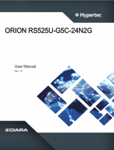
1.2 Serial number label
The product’s serial number contains 12 characters such as xxSxxxxxxxxx and printed on the
sticker at the server's front cover.
The correct serial number of the product is required if you need to request for support from
the ASUS Technical Support team.
xxSxxxxxxxxx
RS300-E11-RS4 /
RS300-E11-PS4
1234

Chapter 1: Product Introduction
1-4
1.3 System specifications
The ASUS RS300-E11 Series features the ASUS P12R-M/SYS server board. The server
supports Intel® Xeon® E and Intel® Pentium™ processors plus other latest technologies
through the chipsets onboard.
(continued on the next page)
Model Name RS300-E11-RS4 RS300-E11-PS4
Motherboard P12R-M/SYS
Processor Support
1 x Socket H5 (LGA 1200)
Intel® Xeon® E processor (up to 95W)
Intel® Pentium™ processor
Core Logic Intel® C252 Chipset
Memory
Total Slots 4 (2-channels)
Capacity Maximum up to 128GB (UDIMM)
Memory Type DDR4 3200/2933/2666 ECC UDIMM
* Please refer to www.asus.com for latest momory AVL update
Memory Size 32GB, 16GB, 8GB, 4GB (UDIMM)
* Refer to www.asus.com/support for more information
Expansion
Slots
Total PCI/PCIe/
PIKE Slots Up to 3
Slot Type
Butterfly Riser Slot A:
1 x PCIe x16 (Gen4 x16 Link, switch to x8 link when slot B
occupied), FH/HL
Butterfly Riser Slot B:
1 x PCIe x8 (Gen4 x8 Link), HH/HL
M.2 1 x M.2 (Up to 2280)(from PCH)
(support PCIe M.2)
Proprietary Slot 1
Motherboard SlotC:
1 x PCIe x 8 (Gen3 x 4 Link), Proprietary
(optional for Intel® X710 10G LAN card)
Proprietary Slot 2 -
Storage
SATA Controller
Intel® C252:
6 x SATA 6Gb/s ports
Intel® VROC (Windows & Linux)
(Support software RAID 0, 1, 10 & 5)
SAS Controller
Optional kits:
ASUS PIKE II 3008 8-port SAS 12Gb/s HBA card
ASUS PIKE II 3108 8-port SAS HW 12Gb/s RAID card
Broadcom MegaRAID 9560-16i

ASUS RS300-E11 Series 1-5
Model Name RS300-E11-RS4 RS300-E11-PS4
Storage
Bays
Storage Bay
4 x 3.5” Hot-Swap storage bays
- up to (2 x SATA/SAS/NVMe + 2 x SATA/SAS)
* SAS support only from optional SAS HBA/RAID card
* NVMe support only from optional NVMe upgrade kit
Backplane
connectors
2 x NVMe connectors
1 x Mini SAS HD connector
Motherboard on-
board connectors
6 x SATA connectors
1 x M.2 connector
Default cable 1 x SATA to Mini SAS HD cable
NVMe upgrade
option
NVMe upgrade option
Support 2 x NVMe: 2-port NVMe upgrade kit (1 x riser card +1
x cables + 2 x NVMe HS)
Networking 2 x Intel® I210-AT
1 x Management Port
Graphic
VGA Aspeed AST2600 64MB
* VGA output from BMC
HDMI HDMI 1.4
* HDMI output from CPU
Auxiliary Storage Device Bay
(Floppy / Optical Drive)
1 x Slim-type Optical Drive Bay
Options: No Device / DVD-RW / DVD-ROM
Front I/O Ports 1 x VGA port
2 x USB 3.2 Gen 1 ports
Rear I/O Ports
2 x USB 3.2 Gen 2 ports
1 x VGA port*
1 x HDMI™ port from CPU
1 x COM port
2 x RJ-45 ports
1 x RJ-45 ports (One for ASMB10-iKVM)(Optional)
* Only supported with ASMB10
Switch/LED
Rear Switch/LED:
1 x Q-Code/Port 80 LED
1 x Power switch
Front Switch/LED:
1 x Power switch/LED
1 x Location switch/LED
1 x Reset switch
1 x HDD Access LED
1 x Message LED
LAN 1-2 LED
(continued on the next page)

Chapter 1: Product Introduction
1-6
*Specifications are subject to change without notice.
Model Name RS300-E11-RS4 RS300-E11-PS4
OS Support
Windows® Server 2022
RedHat® Enterprise Linux
SuSE® Linux Enterprise Server
CentOS
* Please find the latest OS support from https://www.asus.com/
Management
Solution
Software ASUS Control Center
Out of Band
Remote
Management
On-Board ASMB10-iKVM for KVM-over-IP
Regulatory Compliance BSMI, CE, C-TICK, FCC (Class A)
Dimension 497mm x 439.5mm x 44mm (2U)
Net Weight Kg (CPU, DRAM &
HDD not included) 10.3 Kg 8.47 Kg
Gross Weight Kg (CPU, DRAM
& HDD not included, Packing
include)
15.3 Kg 13.47 Kg
Power Supply
(different configuration by region)
1+1 Redundant 450W 80 PLUS
PLATINUM Power Supply
Rating: 100-240Vac, 6A (for
each inlet), 50-60Hz, Class I
Single 350W 80 PLUS Gold
Power Supply
Rating: 100-240Vac, 6-3A (for
each inlet), 50-60Hz, Class I
Environment
Operation temperature: 10°C ~ 35°C
Non operation temperature: -40°C ~70°C
Non operation humidity: 20% ~ 90% (Non condensing)

ASUS RS300-E11 Series 1-7
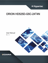
1.4 Front panel features
The barebone server displays a simple yet stylish front panel with easily accessible features.
The power and reset buttons, LED indicators are located on the front panel.
Refer to section 1.7 LED information for the LED descriptions.
• * This port is for ASUS ASMB10-iKVM only.
• The Q-Code LED provides the most probable cause of an error code as a starting
point for troubleshooting. The actual cause may vary from case to case.
• Refer to the Q-Code table for details.
1.5 Rear panel features
The rear panel includes the expansion slots, and system power sockets. The middle part
includes the I/O shield with openings for the rear panel connectors on the motherboard.
RS300-E11-RS4
Bay 1 to bay 4 supports NVMe/SATA/SAS. SAS support requires optional HBA/RAID card.
1234
USB 3.2 Gen 1 ports
Front panel LEDs
4 x 3.5” Storage Bays
Slim-type Optical Drive Bay
(optoinal) VGA port
Power button with LED
Location button with LED
Reset button
Redundant Power supply
and Power cord connector
Expansion slots
COM port
Management LAN port 1*
LAN port 1
VGA port
LAN port 2
USB 3.2 Gen 2 ports
HDMI™ port
Q-Code LED
Power button
Expansion slot

Chapter 1: Product Introduction
1-8
• * This port is for ASUS ASMB10-iKVM only.
• The Q-Code LED provides the most probable cause of an error code as a starting
point for troubleshooting. The actual cause may vary from case to case.
• Refer to the Q-Code table for details.
RS300-E11-PS4
Power supply and Power
cord connector
Expansion slots
COM port
Management LAN port 1*
LAN port 1
VGA port
LAN port 2
USB 3.2 Gen 2 ports
HDMI™ port
Q-Code LED
Power button
Expansion slot

ASUS RS300-E11 Series 1-9
1.6 Internal features
The barebone server includes the basic components as shown.
The barebone server does not include a floppy disk drive. Connect a USB floppy disk drive
to any of the USB ports on the front or rear panel if you need to use a floppy disk.
WARNING
HAZARDOUS MOVING PARTS
KEEP FINGERS AND OTHER BODY PARTS AWAY
A protection film is pre-attached to the front cover before shipping. Please remove the
protection film before turning on the system for proper heat dissipation.
1. Redundant Power supply
2. ASUS P12R-M/SYS Server Board
3. SATA/SAS/NVMe back panel
4. System fans
RS300-E11-RS4
5. Asset Tag (hidden)
6. 4 x 3.5“ storage device trays
7. PCIe riser card

Chapter 1: Product Introduction
1-10
The barebone server does not include a floppy disk drive. Connect a USB floppy disk drive
to any of the USB ports on the front or rear panel if you need to use a floppy disk.
WARNING
HAZARDOUS MOVING PARTS
KEEP FINGERS AND OTHER BODY PARTS AWAY
A protection film is pre-attached to the front cover before shipping. Please remove the
protection film before turning on the system for proper heat dissipation.
1. Power supply
2. ASUS P12R-M/SYS Server Board
3. SATA/SAS/NVMe back panel
4. System fans
RS300-E11-PS4
5. Asset Tag (hidden)
6. 4 x 3.5“ storage device trays
7. PCIe riser card
Page is loading ...
Page is loading ...
Page is loading ...
Page is loading ...
Page is loading ...
Page is loading ...
Page is loading ...
Page is loading ...
Page is loading ...
Page is loading ...
Page is loading ...
Page is loading ...
Page is loading ...
Page is loading ...
Page is loading ...
Page is loading ...
Page is loading ...
Page is loading ...
Page is loading ...
Page is loading ...
Page is loading ...
Page is loading ...
Page is loading ...
Page is loading ...
Page is loading ...
Page is loading ...
Page is loading ...
Page is loading ...
Page is loading ...
Page is loading ...
Page is loading ...
Page is loading ...
Page is loading ...
Page is loading ...
Page is loading ...
Page is loading ...
Page is loading ...
Page is loading ...
Page is loading ...
Page is loading ...
Page is loading ...
Page is loading ...
Page is loading ...
Page is loading ...
Page is loading ...
Page is loading ...
Page is loading ...
Page is loading ...
Page is loading ...
Page is loading ...
Page is loading ...
Page is loading ...
Page is loading ...
Page is loading ...
Page is loading ...
Page is loading ...
Page is loading ...
Page is loading ...
Page is loading ...
Page is loading ...
Page is loading ...
Page is loading ...
Page is loading ...
Page is loading ...
Page is loading ...
Page is loading ...
Page is loading ...
Page is loading ...
Page is loading ...
Page is loading ...
Page is loading ...
Page is loading ...
Page is loading ...
Page is loading ...
Page is loading ...
Page is loading ...
Page is loading ...
Page is loading ...
Page is loading ...
Page is loading ...
Page is loading ...
Page is loading ...
Page is loading ...
Page is loading ...
Page is loading ...
Page is loading ...
Page is loading ...
Page is loading ...
Page is loading ...
Page is loading ...
Page is loading ...
Page is loading ...
Page is loading ...
Page is loading ...
Page is loading ...
Page is loading ...
Page is loading ...
Page is loading ...
Page is loading ...
Page is loading ...
Page is loading ...
Page is loading ...
Page is loading ...
Page is loading ...
Page is loading ...
Page is loading ...
Page is loading ...
Page is loading ...
Page is loading ...
Page is loading ...
Page is loading ...
Page is loading ...
Page is loading ...
Page is loading ...
Page is loading ...
Page is loading ...
Page is loading ...
Page is loading ...
Page is loading ...
Page is loading ...
Page is loading ...
Page is loading ...
Page is loading ...
Page is loading ...
Page is loading ...
Page is loading ...
Page is loading ...
Page is loading ...
Page is loading ...
Page is loading ...
Page is loading ...
Page is loading ...
Page is loading ...
Page is loading ...
Page is loading ...
Page is loading ...
Page is loading ...
Page is loading ...
Page is loading ...
Page is loading ...
Page is loading ...
Page is loading ...
Page is loading ...
Page is loading ...
Page is loading ...
Page is loading ...
Page is loading ...
Page is loading ...
Page is loading ...
Page is loading ...
Page is loading ...
Page is loading ...
Page is loading ...
Page is loading ...
Page is loading ...
Page is loading ...
Page is loading ...
Page is loading ...
Page is loading ...
Page is loading ...
Page is loading ...
Page is loading ...
/