Carrier Aquazone 50QE900-NPWS Installation and Operating Instructions
- Category
- Thermostats
- Type
- Installation and Operating Instructions

Manufacturer reserves the right to discontinue, or change at any time, specifications or designs without notice and without incurring obligations.
PC 111 Catalog No. 535-00107 Printed in U.S.A. Form 50QE-6SI Pg 1 1107 6-03 Replaces: New
Book 1 4
Ta b 5 a 5 a
Installation and Operating Instructions
Part Number 50QE900-NPWS
SAFETY CONSIDERATIONS
Read and follow manufacturer instructions carefully. Fol-
low all local electrical codes during installation. All wiring
must conform to local and national electrical codes. Improper
wiring or installation may damage thermostat.
Recognize safety information. This is the safety alert sym-
bol . When the safety alert symbol is present on equipment
or in the instruction manual, be alert to the potential for person-
al injury.
Understand the signal words DANGER, WARNING, and
CAUTION. These words are used with the safety alert symbol.
DANGER identifies the most serious hazards which will result
in severe personal injury or death. WARNING signifies a haz-
ard which could result in personal injury or death. CAUTION
is used to identify unsafe practices which would result in minor
personal injury or property damage.
GENERAL
The commercial, non-programmable thermostats are wall-
mounted, low-voltage thermostats which maintain room tem-
perature by controlling the operation of an HVAC (heating,
cooling and ventilation) system. Separate heating and cooling
set points and auto-changeover capability allow for greater
flexibility.
Batteries are not required. During power interruption the in-
ternal NEVERLOST™ memory stores configuration settings
for an unlimited time.
The thermostat can be configured to accept several different
equipment configurations, and is provided for heat pump
operation.
The temperature display range of the thermostat is 32 to
99 F (0° to 36 C).
INSTALLATION
Select Thermostat Location — The thermostat should
be mounted:
• approximately 5 ft from the floor
• close to or in a frequently used room, preferably on an
inside partitioning wall
• on a section of wall without pipes or ductwork
• where temperature operating limits are within 32 to
122 F (0° to 50 C)
• where humidity operating range is within 0 to 95% rela-
tive humidity, non-condensing
The thermostat should NOT be mounted:
• close to a window, on an outside wall, or next to a door
leading to the outside
• where exposed to direct light and heat from a lamp, the
sun, a fireplace, or any other temperature-radiating
object which may cause a false reading
• close to or in direct airflow from supply registers or
return-air grilles
• in areas with poor air circulation (such as behind a door
or in an alcove)
Install Thermostat
1. Turn off all power to unit.
2. If an existing thermostat is being replaced:
a. Remove existing thermostat from the wall.
b. Disconnect wires from existing thermostat. Do not
allow wires to fall back into the wall. As each wire
is disconnected, record wire color and terminal
connection.
c. Discard or recycle old thermostat.
NOTE: Mercury is a hazardous waste and must be
disposed of properly.
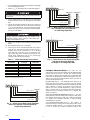
3. Remove the thermostat cover from wall plate (mounting
base) to expose mounting holes. See Fig. 1.
4. Route thermostat wires through large hole in mount-
ing base. Remove outer sheath from wires for added flex-
ibility. Standard solid or multi-conductor thermostat wire
should be used from the thermostat to the unit. Size and
length considerations are as follows: for a maximum
distance from unit of 36 ft, use 22 AWG (American
Wire Gage) wire; for a maximum distance from unit
of 100 ft, use 18 AWG wire.
IMPORTANT: Read entire instructions before starting
the installation.
Before installing thermostat, turn off all power to the unit.
There may be more than one power disconnect. Electrical
shock can cause injury or death.
50QE900
Aquazone™ Water Source Heat Pump
Commercial Non-Programmable Thermostat
WIRING
TERMINAL
BLOCK
HOLE FOR
WIRING
MOUNTING
HOLE
MOUNTING
HOLE
C
Y1 W2
G
RW1
B
OY2
3 1/8"
3 1/8" 1"
Fig. 1 — Thermostat Mounting and Wiring

2
5. Level mounting base against wall and mark wall through
the 2 mounting holes in base.
6. Drill two 3/16-in. mounting holes in wall where marked.
7. Secure mounting base to wall with 2 screws and anchors
provided. Ensure all wires exit through hole in mounting
base.
8. Adjust wire length and routing to allow proper closure of
the thermostat. Strip each wire at the end no more than
1/4-in. to prevent adjacent wires from shorting together.
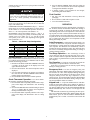
Match and connect wires to terminals on the thermostat.
See Fig. 2-4 and Table 1.
9. Push excess wiring into wall. Seal hole in wall to prevent
drafts.
10. Re-attach thermostat cover to back plate.
11. Turn on power to unit. The thermostat will receive power
from the unit. The thermostat will be powered by 24 v,
nominal (18 to 30 vac). Terminals R (+ 24 v), W1/O/B
(first stage heat or reversing valve), Y1 (first stage cool-
ing), G (fan relay) and C (common) will always be con-
nected. Some applications will use Y2 (second stage
cooling) or W2 (second stage heating).
Table 1 — Thermostat Wiring Terminations
*Terminals Y2 and W2 may not be used in all applications.
†Used on Heat Pump applications only.
Configure Advanced Setup — To enter the ad-
vanced setup screens of the thermostat, press the Mode and Fan
buttons at the same time for 7 seconds. The Advanced Setup
Step number is shown in the top right corner of the thermostat
screen. Use the Mode button to advance through the steps. See
Table 2. Press the Mode and Fan buttons at the same time to
exit the Advanced Setup mode.
DEADBAND (Step 1) — The deadband is the difference in
temperature above the cooling set point or below the heating
set point that the thermostat will wait before turning on the first
stage of heating or cooling. For example, if the cooling set
point is 82 F (28 C) and the deadband is 2 degrees, the first
stage of cooling will not be energized until the temperature
reaches 84 F (30 C). The range of values is 1 to 6 degrees. The
default is 2 degrees.
SET POINT MINIMUM DIFFERENCE (Step 2) — The min-
imum difference between heating and cooling set points can be
user-configured. The range is from 0 to 6 degrees. The default
is 2 degrees. The minimum difference is enforced during
Autochangeover operation.
CYCLES PER HOUR LIMIT (Step 3) — The number of
times that heating or cooling can be energized per hour can be
configured. Set the variable to ‘‘d’’ for no limit. Set the variable
to ‘‘d1’’ to disable the 5-minute compressor lockout. The
Be careful not to drill into wiring in wall. Electrical shock
could result.
Improper wiring or installation may cause damage to the
thermostat. Check to ensure wiring is correct before pro-
ceeding with installation of unit.
EXISTING WIRE
DESIGNATION FUNCTION TERMINAL
CONNECTION
G or F Fan G
Y1, Y, or C Cooling Y1
W1, W, or H Heating W1/O/B
Rh, R, M, Vr, or A Power (24 v) R
CCommon C
O/B Reversing Valve† W1/O/B
Y2 Second Stage Cooling Y2*
W2 Second Stage Heating W2*
Thermostat
RR
CC
GG
YY
WW
OO
RC
G
Y1
Y2 W1
W2
O
24 vac common
24 vac return
Fan
Compressor
Compressor 2
Cooling
COMPLETE C1 COMPLETE C2
B
Thermostat
R
C
G
Y1
Y2
W1
O/W2
RC
G
Y1
Y2 W1
W2
O
24 vac common
24 vac return
Fan
Compressor 1
Compressor 2
Cooling
DELUXE D
B
Fig. 3 — Water Source Heat Pumps Equipped
with 2 Complete C Control Boards
for Two-Stage Operation
Fig. 4 — Water Source Heat Pumps Equipped
with Deluxe D Control Board(s)
for Single or Two-Stage Operation
Thermostat
R
C
G
Y
W
O
RC
G
Y1
Y2 W1
W2
O
24 vac common
24 vac return
Fan
Compressor
Cooling
COMPLETE C
B
Fig. 2 — Water Source Heat Pumps Equipped
with One Complete C Control Board for
Single-Stage Operation
→
1107

3
variable can also be set from 2 to 6 cycles per hour. The default
is 6 cycles per hour.
BACKLIGHT DISPLAY (Step 4) — The display backlight
can be set to ON (always on) or OFF (turn off 8 seconds after
usage). The default is ON.
FAHRENHEIT/CELSIUS OPERATION (Step 5) — The ther-
mostat can be set to operate in Fahrenheit or Celsius degrees.
Set the variable to ‘‘F’’ for Fahrenheit operation. Set the vari-
able to ‘‘C’’ for Celsius operation. The default is ‘‘F.’’
REVERSING VALVE POLARITY (Step 6) — Step 6 is
used to set the reversing valve polarity for the heat pump. The
variable can be set to either ‘‘B’’ or ‘‘O.’’ Set the reversing
valve polarity to the correct value depending on the applica-
tion. The default is ‘‘O.’’
Table 2 — Advanced Setup Configuration
Calibrate Sensor — Every thermostat is factory cali-
brated. Under normal circumstances there will never be a need
to re-calibrate the thermostat. If re-calibration must be done,
perform the following procedure:
1. Hold down the Mode and DOWN ARROW buttons for
5 seconds. All of the icons on the display screen will
appear. Release the buttons.
2. Press the Mode button. The current temperature will be
displayed.
3. Use an accurate thermometer to measure room tempera-
ture. Press the UP or DOWN ARROW buttons until the
number equals room temperature.
4. Press the Mode button to return to normal operation.
Check Thermostat Operation — To check thermo-
stat operation, perform the following procedure:
1. Press the Mode button repeatedly until the Heat icon ap-
pears on the display. The thermostat is now in Heating
mode.
2. Press the UP ARROW button until the heating set point is
10 F (6 C) higher than the current room temperature
Heating and fan should be energized.
3. Press the Mode button repeatedly until the Cool icon ap-
pears on the display. The thermostat is now in Cooling
mode.
4. Press the DOWN ARROW button until the cooling set
point is 10 F lower than the current room temperature.
Cooling and fan should be energized.
5. If heating, cooling, or fan operation do not energize,
check wiring and consult Table 3.
Final Checklist
1. Put away tools and instruments. Clean up debris and
packaging.
2. Review Owner’s Guide with occupant or owner.
3. Leave the manuals with owner.
OPERATION
The Mode button selects the operating mode of the thermo-
stat. If OFF is selected, the thermostat will not enter Heating or
Cooling mode. If HEAT is selected, the thermostat will only
enter Heating mode (if the room temperature is below the heat-
ing set point). If COOL is selected, the thermostat will only en-
ter Cooling mode (if the room temperature is above the cooling
set point). If AUTO is selected, the thermostat will enter Heat-
ing or Cooling mode based on the room temperature and the
heating and cooling set points.
Auto-Changeover — When the thermostat mode is set
to AUTO, the thermostat will provide automatic changeover
from Heating to Cooling mode and Cooling to Heating mode
when required. The thermostat will automatically switch to
maintain the desired temperature setting. The thermostat does
not need to be manually changed from heating to cooling or
cooling to heating operation.
Two-Stage Operation — The second stage of heat or
cool is turned on when the first stage has been on for a mini-
mum of 2 minutes and the temperature differential from the set
point is equal to or greater than the set point plus the deadband
plus 2 degrees.
Fan Operation — If Fan On is selected, the fan will run
continuously (except when Mode is switched to OFF).
If Fan On is not selected, the fan will only operate during
heating or cooling operation.
Emergency Heat — To turn on emergency heat, press
and hold the Fan button. While holding the Fan button, press
the UP button. An ‘‘EH’’ will be displayed. During emergency
heat, the fan will operate and the second stage of heat will be
energized (locking out the first stage compressor). To exit
emergency heat, press and hold the Fan button. While holding
the Fan button, press the UP button. During emergency heat,
only OFF and HEAT modes are available.
Keypad Lock — To prevent unauthorized use of the ther-
mostat, the front panel buttons can be disabled. To disable or
lock the keypad, press and hold the Mode button. While hold-
ing down the Mode button, press the UP and DOWN ARROW
buttons simultaneously. The ‘‘Locked’’ icon will appear on the
display.
The thermostat is unlocked by performing the same proce-
dure. Press and hold the Mode button. While holding down the
Mode button, press the UP and DOWN ARROW buttons
simultaneously. The ‘‘Locked’’ icon will be removed from the
display.
Damage to compressor could result if 5-minute compressor
lockout is disabled or compressor is allowed unlimited
cycles. Do not set thermostat Advanced Setup Step 3 to
‘‘d’’ or ‘‘d1’’ unless specifically recommended for the
application.
STEP DESCRIPTION RANGE DEFAULT
1Deadband 1 - 6 degrees 2
2Forced Minimum
Temperature Difference 0 - 6 degrees 2
3Cycles per Hour d, d1, 2 - 6 6
4Thermoglow™ Backlight Off/On On
5Temperature Units F/C F
6Reversing Valve Polarity O/B O

Manufacturer reserves the right to discontinue, or change at any time, specifications or designs without notice and without incurring obligations.
PC 111 Catalog No. 535-00107 Printed in U.S.A. Form 50QE-6SI Pg 4 1107 6-03 Replaces: New
Book 1 4
Ta b 5 a 5 a
Copyright 2003 Carrier Corporation
TROUBLESHOOTING
Table 3 — Troubleshooting
PROBLEM SOLUTION
Display on thermostat not illuminated. Check for 24 vac at the R terminal connection. Terminal R must be connected for proper
thermostat operation.
Cooling will not energize. Select COOL mode. Decrease cooling set point to 10 degrees below room temperature.
Check for 24 vac at Y1 terminal. If present, thermostat is operating correctly and problem
is with wiring or equipment. If 24 vac is not present, replace the thermostat. Check for
Compressor Cycle per Hour Limit. Cooling may be locked out.
Heating will not energize. Select HEAT mode. Increase heating set point to 10 degrees above room temperature.
Check for 24 vac at W1/O/B terminal. If present, thermostat is operating correctly and
problem is with wiring or equipment. If 24 vac is not present, replace the thermostat.
-
 1
1
-
 2
2
-
 3
3
-
 4
4


Carrier Aquazone 50QE900-NPWS Installation and Operating Instructions
- Category
- Thermostats
- Type
- Installation and Operating Instructions
Ask a question and I''ll find the answer in the document
Finding information in a document is now easier with AI
Related papers
Other documents
-
Bryant P/N TSTATBBP220-LA User manual
-
-
AMX ENV-VST-C User manual
-
Bryant LEGACY T2-PAC User manual
-
Honeywell COMMERCIALPRO TB7220 User manual
-
American Standard X13511537-01 Specification
-
Venstar T3800 User manual
-
-
-