
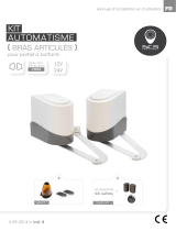
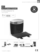
Modular control unit for one or two 24 Vdc motors
Logique de commande modulaire pour un ou deux moteurs 24 Vcc
Modulares Steuergerät für einen oder zwei 24-VDC-Motoren
14A
Instructions and warnings for installation and use
Anleitungen und Hinweise zu Installation und Einsatz
Instructions et avertissements pour l’installation et l’usage

2
EN
1
2
3
4
5
6
7
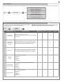
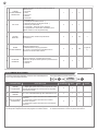
Safety warnings
2.1
2.2
2.3
2.4
4.1
4.2
4.3
4.4
4.5
4.6
4.7
4.8
6.1
6.2
6.3
5.1
5.2
Product Introduction
Description of the control unit
Description of the connections
Models and technical characteristics
List of cables required
Preliminary Checks
Installing the Product
Electric connections
Using the display programmer
Auto-learning of the travel stroke
Operating the automation using
the display programmer
Operating the automation using
the receiver
Diagnostic
Customising the system -
BASIC SETTINGS
NIGHT LIGHTS
Details
Customising the system -
ADVANCED SETTINGS
RX4X RECEIVER
Programmer ow chart
Testing and commissioning
Testing
Commissioning
Instructions and warnings for the
nal user
page 3
page 4
page 4
page 4
page 4
page 5
page 5
page 6
page 6
page 7
page 8
page 8
page 8
page 9
page 9
page 10
page 11
page 11
page 11
page 12
page 12
page 14
page 15
page 16
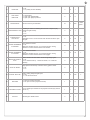
TABLE OF CONTENTS

3
EN
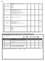
1 - SAFETY WARNINGS
CAUTION – ORIGINAL INSTRUCTIONS - important safety in-
structions. Compliance with the safety instructions below is
important for personal safety. Save these instructions.
Read the instructions carefully before proceeding with installation.
The design and manufacture of the devices making up the
product and the information in this manual are compliant with
current safety standards. However, incorrect installation or
programming may cause serious injury to those working on or
using the system. Compliance with the instructions provided
here when installing the product is therefore extremely impor-
tant.
If in any doubt regarding installation, do not proceed and contact the
Magifer Technical Service for clarications.
Under European legislation, an automatic door or gate system
must comply with the standards envisaged in the Directive
2006/42/EC (Machinery Directive) and in particular standards
EN 12445; EN 12453; EN 12635 and EN 13241-1, which enable
declaration of presumed conformity of the automation system.
Therefore, nal connection of the automation system to the electri-
cal mains, system testing, commissioning and routine maintenance
must be performed by skilled, qualied personnel, in observance of
the instructions in the “Testing and commissioning the automation
system” section.
The aforesaid personnel are also responsible for the tests required
to verify the solutions adopted according to the risks present, and
for ensuring observance of all legal provisions, standards and regu-
lations, with particular reference to all requirements of the EN 12445
standard which establishes the test methods for testing door and
gate automation systems.
WARNING - Before starting installation, perform the following
checks and assessments:
ensure that every device used to set up the automation system is
suited to the intended system overall. For this purpose, pay special
attention to the data provided in the “Technical specications” sec-
tion. Do not proceed with installation if any one of these devices is
not suitable for its intended purpose;
check that the devices purchased are sufcient to guarantee system
safety and functionality;
perform a risk assessment, including a list of the essential safety
requirements as envisaged in Annex I of the Machinery Directive,
specifying the solutions adopted. The risk assessment is one of the
documents included in the automation system’s technical le. This
must be compiled by a professional installer.
Considering the risk situations that may arise during instal-
lation phases and use of the product, the automation system
must be installed in compliance with the following safety pre-
cautions:
never make modications to any part of the automation system
other than those specied in this manual. Operations of this type
can only lead to malfunctions. The manufacturer declines all liability
for damage caused by unauthorised modications to products;
if the power cable is damaged, it must be replaced by the manufac-
turer or its after-sales service, or in all cases by a person with similar
qualications, to prevent all risks;
do not allow parts of the automation system to be immersed in water
or other liquids. During installation ensure that no liquids are able to
enter the various devices;
should this occur, disconnect the power supply immediately and
contact a Magifer Service Centre. Use of the automation system in
these conditions may cause hazards;
never place automation system components near to sources of heat
or expose them to naked lights. This may damage system compo-
nents and cause malfunctions, re or hazards;
all operations requiring opening of the protective housings of va-
rious automation system components must be performed with the
control unit disconnected from the power supply. If the disconnect
device is not in a visible location, afx a notice stating: “MAINTE-
NANCE IN PROGRESS”:
connect all devices to an electric power line equipped with an
earthing system;
the product cannot be considered to provide effective protection
against intrusion. If effective protection is required, the automation
system must be combined with other devices;
the product may not be used until the automation system “commis-
sioning” procedure has been performed as specied in the “Auto-
mation system testing and commissioning” section;
the system power supply line must include a circuit breaker device
with a contact gap allowing complete disconnection in the condi-
tions specied by class III overvoltage;
use unions with IP55 or higher protection when connecting hoses,
pipes or cable glands;
the electrical system upstream of the automation system must com-
ply with the relevant regulations and be constructed to good wor-
kmanship standards;
users are advised to install an emergency stop button close to the
automation system (connected to the control PCB STOP input) to
allow the door to be stopped immediately in case of danger;
this device is not intended for use by persons (including children)
with impaired physical, sensory or mental capacities, or with lack
of experience or skill, unless a person responsible for their safety
provides surveillance or instruction in use of the device;
before starting the automation system, ensure that there is no-one
in the immediate vicinity;
before proceeding with any cleaning or maintenance work on the
automation system, disconnect it from the electrical mains;
special care must be taken to avoid crushing between the part ope-
rated by the automation system and any xed parts around it;
children must be supervised to ensure that they do not play with the
equipment.
WARNING - The automation system component packaging ma-
terial must be disposed of in full observance of current local
waste disposal legislation.
WARNING - The data and information in this manual are subject
to modication at any time, with no obligation on the part of
Magifer to provide notice.

4
EN
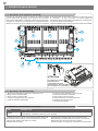
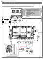
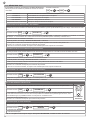
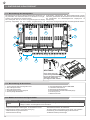
2.1 - Description of the control unit
The 14A control unit is a modular system for the control of Key
Automation motors for the electric opening and closure of swing and
sliding gates, barriers and garage doors.
The 14A has a programmer with display (optional) allowing easy
programming and constant monitoring of the control unit’s status;
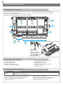
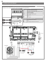
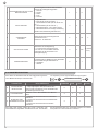
2.2 - Description of the connections
1- Control unit power supply connection 24 Vac
2- M1 power module socket
3- M2 power module socket
4- Display programmer connector
5- Receiver compartment RX4X/RX4U
6- Integrated STEP BY STEP control button
7- External antenna connections
8- Input status indicator LEDs
9- Accessory/input connection terminal board
10- Protective fuse, 2.5AT
11 - Battery connection
WARNING:
the PO24 power
module must always
be connected/disconnected
with the control
unit not powered up!
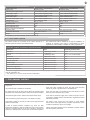
2.3 - Models and technical characteristics
the menu structure also allows easy setting of working times and
operating modes. The display menu is multilingual.
All other, improper, use of the control unit is forbidden.
2 - INTRODUCING THE PRODUCT
CODE DESCRIPTION
900MA24 Logic module for combination with 1 or 2 PO24 power modules for the control of 1 or 2 24V motors for swing and
sliding gates, barriers and garage doors
SBS
M1
M2
COM
PED
OPEN
CLOSE
SBS
NEG
PH-POW
PH1
PH2
COM
FLASH
LED
SEN
SHIELD
ANT
COM
STOP
EDGE
EDGE
COM
ELEC
COM
IND
STOP
EDGE
PH1
PH2
PED
OPEN
CLOSE
SBS
POWER
SUPPLY
23
4
6
5
78
9
10
11
1
- Power supply with protection against short-circuits inside the
control unit, on motors and on the connected accessories.
- Obstacle detection by means of current sensor.
- Anti-crush safety device.
- Automatic learning of working times.
- Programmable deceleration during opening and closure.
- Safety input deactivation by means of software.
- Control panel with microprocessor logic.
BATTERIES
(ACCESSORY)

5
EN
3 - PRELIMINARY CHECKS
2.4 - List of cables required
The cables required for connection of the various devices in a
standard system are listed in the cables list table.
Before installing the product, perform the following checks and
inspections:
check that the gate is suitable for automation;
the weight and size of the gate must be within the operating limits
specied for the automation system in which the product is installed;
check that the gate has rm, effective mechanical safety stops;
make sure that the product xing zone is not liable to ooding;
high acidity or salinity or proximity to heat sources might cause the
product to malfunction;
in case of extreme weather conditions (e.g. snow, ice, wide
temperature variations or high temperatures), friction may increase,
causing a corresponding rise in the force needed to operate the
system; the starting torque may therefore exceed that required in
normal conditions;
check that, when operated by hand, the gate moves smoothly
without any areas of greater friction or derailment risk;
check that the gate is well balanced and will therefore remain
stationery when released in any position;
check that the electricity supply line to which the product is to be
connected is suitably earthed and tted with magnetothermal and
differential protection;
the system power supply line must include a circuit breaker
device with a contact gap allowing complete disconnection in the
conditions specied by class III overvoltage;
ensure that all the material used for installation complies with the
relevant regulatory standards.
The cables used must be suitable for the type of installation; for
example, an H03VV-F type cable is recommended for indoor
applications, while H07RN-F is suitable for outdoor applications.
TECHNICAL CHARACTERISTICS
Power supply (L-N) 230Vac (+10% - 15%) 50/60 Hz 230Vac (+10% - 15%) 50/60 Hz
Rated power maximum 210W maximum 300W
Photocell power supply output 24Vdc (without regulation) maximum 250mA 24Vdc (without regulation) maximum 250mA
Flashing light output 24Vdc (without regulation) 25W 24Vdc (without regulation) 25W
Courtesy light output 24Vdc (without regulation) 15W 24Vdc (without regulation) 15W
Electric lock output 12Vac maximum 15VA 12Vac maximum 15VA
Gate open warning light output 24Vdc (without regulation) 5W 24Vdc (without regulation) 5W
Antenna input 50Ω RG58 type cable 50Ω RG58 type cable
Operating temperature -20 °C + 55 °C -20 °C + 55 °C
Accessory fuses 2.5AT 2.5AT
Power supply line fuses 2AT 2AT
Use in particularly acid,
saline or explosive atmospheres NO NO
Protection class IP54 (inside protective casing) IP54 (inside protective casing)
Control unit dimensions 183 x 102 x 59 H mm 183 x 102 x 59 H mm
Weight 4,3 kg 4,5 kg
* If the power supply cable is more than 20 m long, it must be of larger gauge (3x2.5mm2) and a safety grounding system must be installed
near the automation unit.
** Two cables of 2 x 0.5 mm2 can be used as an alternative
ELECTRIC CABLE TECHNICAL SPECIFICATIONS
Connection cable maximum permitted limit
Power line 1 cable of 3 x 1.5 mm220 m *
Flashing light, Courtesy light, ambient light sensor
Antenna
4 x 0.5 mm2**
1 RG58 type cable
20 m
20 m (< 5 m recommended)
Electric lock 1 cable of 2 x 1 mm210 m
Transmitter photocells 1 cable of 2 x 0.5 mm220 m
Receiver photocells 1 cable of 4 x 0.5 mm220 m
Sensitive edge 1 cable of 2 x 0.5 mm220 m
Key-operated selector switch 1 cable of 4 x 0.5 mm2** 20 m
Motor power supply line 1 cable of 2 x 1.5 mm210 m
Encoder power supply line 1 cable of 3 x 0.5 mm210 m
* Compulsory for motors: RAY4024, SN-50-24 and INT-24

6
EN
4 - INSTALLING THE PRODUCT
PO24 POWER MODULE
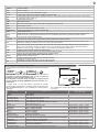
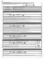
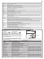
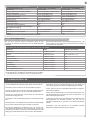
4.1 - Electrical connections
WARNING - Before making the connections, ensure that the control unit is not powered up
COM
PED
OPEN
CLOSE
SBS
NEG
PH-POW
PH1
PH2
COM
FLASH
LED
SEN
SHIELD
ANT
COM
STOP
EDGE
EDGE
COM
ELEC
COM
IND
POWER
SUPPLY
N
T2A
L
230Vac
50/60Hz
PHOTOTEST
LIGHT
TWILIGHT SENSOR
OUTPUT LED
STOP
OPEN
PHOTOCELL 1
PHOTOCELL 2
CLOSE
PEDESTRIAN
STEP BY STEP
+ COMMON
+ COMMON
SAFETY EDGE
ELECTRIC LOCK
NEGATIVE
SBS
M1
M2
BATTERIES
(ACCESSORY)
COM
LED FLASH SEN
234
112
TX RX
NC
PH1 234
112
TX RX
PH2
GND
_12/24
AC/DC GND
_12/24
AC/DC COM OUT
GND
_12/24
AC/DC GND
_12/24
AC/DC COM OUT
NC
LS1
LS2
V +
ENC
NEG
M -
M +
M
ENCODER POWER
SUPPLY +
ENCODER POWER
SUPPLY -
ENCODER
PO24 CONNECTIONS
LS1 Limit switch 1 input (only for SUN)
LS2 Limit switch 2 input (only for SUN)
V+ Limit switch / encoder power supply positive common
(12 Vdc 50 mA MAX)
ENC Encoder S signal input
NEG Encoder power supply negative
M- Motor output
Earth
M+ Motor output
POWER SUPPLY CONNECTIONS
LPower supply 230 Vac 50-60 Hz
Earth
NPower supply neutral 230 Vac 50-60 Hz
TRANSFORMER
ECLIPSE
M1M2
M2M1

7
EN
MA24 ELECTRIC CONNECTIONS
SHIELD Antenna - shield -
ANT Antenna - signal -
COM Common for FLASH, LED, SEN inputs / outputs
FLASH Flashing light output 24Vdc (without regulation) maximum 25W
LED Courtesy light output 24Vdc (without regulation) maximum 15W (radio channel 4 selecting COURTESY LIGHT START =
2, COURTESY LIGHT TIME = 0 )
SEN Ambient light sensor input
COM IND output common
IND Gate open warning light output, 24Vdc (without regulation) maximum 4W
COM ELEC output common
ELEC Electric lock output 12Vac, maximum 15VA
EDGE/EDGE Sensitive edge output, NC contact or resistive 8k2
COM STOP output common
STOP Safety STOP NC contact between STOP and COM. This input is considered as a safety device; the contact may be
broken at any time, cutting out the automation at once and disabling all functions, including automatic closure
NEG Photocell power supply negative output
PH-POW Photocell power supply positive output, 24Vdc (without regulation, maximum 250mA
PH1 Photocells (closure), NC contact between PH1 and COM. The photocell is tripped at any time during closure of the
automation, stopping movement at once and reversing the travel direction
PH2 Photocells (opening), NC contact between PH2 and COM. The photocell is tripped at any time during opening and
closure of the automation, stopping movement at once; the automation will continue opening when the contact is
restored if it was opening, or continue closing if it was closing (see parameter “PHOTO 2”)
COM Common for PED, OPEN, CLOSE and SBS outputs
PED PEDESTRIAN opening command, NO contact between PED and COM
Used to open the gate partially, depending on the software setting
OPEN OPEN command, NO contact between OPEN and COM
Contact for the opening function
CLOSE CLOSE command, NO contact between CLOSE and COM
Contact for the closing function
SBS STEPPING command, NO contact between SBS and COM
Open/Stop/Close/Stop command, or as set in the software
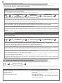
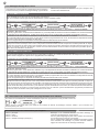
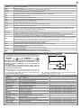
4.2 - Using the display programmer
To customise the programmer’s language and contrast, proceed as
follows:
N.B.: The rst time the display is switched on, the user is
prompted to select the language. Press ▲ or ▼ to select the
language required and then conrm with V.
If no language is selected (X key pressed), the control unit will
use the default language (ENGLISH) until the next time it is
switched on.
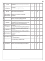
In normal mode, i.e. when the system is powered up normally
and the display programmer is connected, press X until the name
KEY AUTOMATION appears. This will display the following status
messages: The complete ow chart for the display programmer is in point 6.3
on page 31.
EVENT DESCRIPTION KEY TO MAIN CONTROL FLASHING
LIGHT AND LEDS
opening Gate opening
closure Gate closing
automatic closure Gate open with timed reclosure active
stop during closure Gate stopped during closure
stop during opening Gate stopped during opening
open Gate completely open without automatic reclosure
closed Gate completely closed
programmation during the programming phase 2 quick ashes + pause + 1 ash
M1 obstacle Motor 1 obstacle detected 4 quick ashes + pause, 3 times
M2 obstacle Motor 2 obstacle detected 4 quick ashes + pause, 3 times
photo 1! Photocell 1 tripped 2 quick ashes + pause, 3 times
photo 2! Photocell 2 tripped 2 quick ashes + pause, 3 times
sensitive edge! Sensitive edge tripped 5 quick ashes + pause, 3 times
pedestrian opening Pedestrian opening in progress
automatic pedestrian closure Gate opening to pedestrian position with timed reclosure activated
realignment Realignment after a manual release
FLASH/NLS error Night Light System line overload 6 quick ashes + pause, 3 times
ELEC/IND error Electric lock / gate open light line overload 6 quick ashes + pause, 3 times
Phototest error Phototest error detected 3 quick ashes + pause, 3 times
Limit switches error! Limit switch/mechanical end stop error detected 8 quick ashes + pause, 3 times
OPTIONS
DISPLAY
SELECT
LANGUAGE
CONFIRM
SCROLL UP
SCROLL DOWN
CANCEL

8
EN
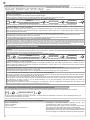
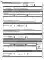
4.3 - Auto-learning of the travel stroke
The rst time the control unit is powered up, an auto-learning
procedure must be carried out to acquire fundamental parameters
such as the travel stroke length and deceleration points.
QUICK PROGRAMMING
If this programming mode is used, the decelerations will reset to the default values with the same percentage during both opening and
closing.
Follow the chart below with the programmer display.
N.B. If the decelerations are also to be programmed, move straight on to the next table.
1. Select the type of installation and the relative type of motor to be installed:
WARNING! Selecting a motor different from the one connected may damage the system.
2. CHECKING CONNECTION OF THE SAFETY DEVICES (PHOTO 1 - PHOTO 2 - SENSITIVE EDGE - STOP BUTTON).
During programming, you will be asked whether there are any safety devices connected to the system. If additional safety devices are con-
nected later, they are simply activated in the relative menu (see advanced parameter table).
3. SAFETY DEVICES ACTIVE/DEACTIVATED DURING AUTO-LEARNING OF TRAVEL STROKE.
If there are safety devices connected, during travel stroke programming, the safety devices can be deactivated to prevent accidental inter-
ruption of this operation. At the end of the auto-learning procedure, the safety devices selected earlier will be reactivated.
4. QUICK AUTO-LEARNING OF TRAVEL STROKE AND DECELERATIONS.
Release the motors and lock them in place again halfway through the travel stroke. If the rst motor operation is not opening, press ▲ or ▼
to reverse the travel direction. M1 must always open before M2. If the motors are inverted, stop the procedure in the control unit by pressing
button X on the display, swap the power supply terminals of the two motors and start again from the beginning. Follow the instructions on
the display.
FULL PROGRAMMING
If this programming mode is used, both the opening and the closing decelerations can be customised.
If no customised settings are made during programming, the control unit will set the default values automatically. Follow the chart below
with the programmer display.
1. Select the type of installation and the relative type of motor to be installed:
WARNING! Selecting a motor different from the one connected may damage the system.
2. CHECKING CONNECTION OF THE SAFETY DEVICES (PHOTO 1 - PHOTO 2 - SENSITIVE EDGE - STOP BUTTON).
During programming, you will be asked whether there are any safety devices connected to the system. If additional safety devices are
connected later, they are simply activated in the relative menu (see advanced parameter table).
3. SAFETY DEVICES ACTIVE/DEACTIVATED DURING AUTO-LEARNING OF TRAVEL STROKE.
If there are safety devices connected, during travel stroke programming, the safety devices can be deactivated to prevent accidental inter-
ruption of this operation. At the end of the auto-learning procedure, the safety devices selected earlier will be reactivated.
4. COMPLETE AUTO-LEARNING OF THE TRAVEL STROKE AND DECELERATIONS.
Release the motors and lock them in place again halfway through the travel stroke. If the rst motor operation is not opening, press ▲
or ▼ to reverse the travel direction. M1 must always open before M2.
If the motors are inverted, stop the procedure in the control unit by pressing button X on the display, swap the power supply terminals of the
two motors and start again from the beginning.
When prompted, press the V key to set the motor’s deceleration point, following the instructions on the display.
It is important to allow for the gate’s moment of inertia and to check that the decelerations set allow the motors to brake the leaves of the
gate before they reach the limit position.
4.4 - Operating the automation using the display programmer
4.5 - Operating the automation using the receiver
To operate the gate in manual mode and check the automation after programming of the travel stroke, proceed as follows:
Use ▲ for step-by-step operation. Use ▼ to switch the night lights on and off. Use V for pedestrian opening and closing to exit the property.
Channel 1: step-by-step
Channel 2: pedestrian
Channel 3: open
Channel 4: lights ON/OFF (note 1)
Note 1: The ON/OFF command switches the lights on or off in
manual mode.
If the Night Light System is active, normal operation of the system
will restart at the next cycle.
If the Night Light System is not active, pressing the switch once
forces switch-on of the lights, while pressing it again resets the
courtesy light operating logic.
14A
14A
QUICK
PROGRAMMING
FULL
PROGRAMMING
INSTALLATION
INSTALLATION
SELECT THE
TYPE OF MOTOR
SELECT THE
TYPE OF MOTOR
14A MANUAL CONTROLS

9
EN
MOTOR 1 CURRENT (mA)
MOTOR 2 CURRENT (mA)
MOTOR 1 POSITION (%)
MOTOR 2 POSITION (%)
MOTOR 1 SPEED (%)
MOTOR 2 SPEED (%)
TOTAL CYCLES (CYCLES)
CYCLES LEFT BEFORE SERVICE
SOFTWARE VERSION
4.6 - Diagnostic
A number of parameters, including the current absorption or motor speed, can be viewed at any time using this function. Proceed as follows:
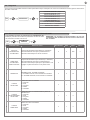
4.7 - Customising the system - BASIC SETTINGS
If necessary, users may select the BASIC SETTINGS, which allow
modication of the control unit’s basic parameters.
Proceed as follows:
PARAMETERS DESCRIPTION DEFAULT MIN. MAX. UNIT
1AUTOMATIC
CLOSING TIME
Automatic reclosure time (0 = off)
Seconds of delay before the gate recloses automatically
after opening
0 0 900 s
2
AUTOMATIC
CLOSING AFTER
TRANSIT
Reclosing time after transit (0 = off) Seconds of delay
before the gate recloses automatically after excitation of
photocell 1 during opening or with the gate open. 0 0 30 s
3SENSITIVITY
Motor sensitivity, sensitivity when detecting an obstacle.
1 = minimum sensitivity, maximum force on obstacle
10 = maximum sensitivity, minimum force on obstacle
3 0 10
4OPENING
SPEED
Motor speed during opening
1 = minimum
2 = low
3 = medium
4 = high
5 = maximum
4 1 5
5SLOW DOWN
OPENING SPEED
Motor speed during opening deceleration phase.
1 = minimum
2 = low
3 = medium
4 = high
5 = maximum
1 1 5
6CLOSING SPEED
Motor speed during closing
1 = minimum
2 = low
3 = medium
4 = high
5 = maximum
4 1 5
14A
14A BASIC
SETTINGS
DIAGNOSTIC
CAUTION: the parameters may vary with respect to those in the
table below, depending on the motor to be installed.

10
EN
4.8 - NIGHT LIGHTS
The night lights function automatically with the Eclipse ashing light
connected appropriately.
The Night Light System switches the lights on or of 15 minutes
after the set threshold is exceeded. This delay is to prevent false
To customise, proceed as follows:
switch-on or switch-off due to external light sources such as car
headlights.
PARAMETERS DESCRIPTION DEFAULT MIN. MAX. UNIT
1AUTOMATIC LIGHT
0 = Night Light System deactivated
1 = Night Light System active (automatically activated
during learning of the stroke with the ECLIPSE ashing
light connected)
001
2LIGHT INTENSIVITY 1 to 5 = Brightness at which LEDs switch on during the
night 315
3EXTERNAL LIGHT
LEVEL
1 = Light sensor tripped with low outdoor light
2 = Light sensor tripped with medium outdoor light
3 = Light sensor tripped with bright outdoor light
213
7SLOW DOWN
CLOSING SPEED
Motor speed during closing deceleration phase.
1 = minimum
2 = low
3 = medium
4 = high
5 = maximum
115
8STEP BY STEP
SS conguration:
0 = Normal (OP-ST-CL-ST-OP-ST…)
1 = Alternate STOP (OP-ST-CL-OP-ST-CL…)
2 = Alternate (OP-CL-OP-CL…)
3 = Apartment block – timer (always opens)
4 = Apartment block with immediate reclosure (always
opens. Closes if gate is open)
004
9MOTOR 2
DELAY
Leaf 2 opening delay with gate closed
0 - 60 sec. 2 0 60 s
10 SLOW DOWN
LENGTH
Deceleration distance
0 = Programming decelerations
1 to 100 = Motor deceleration percentage during
opening and closure
0 0 100 % (step
of 1)
11 ENERGY SAVING
Energy saving: enables photocell switch-off when gate
is closed
0= disabled
1= enabled
001
14A NIGHT LIGHTS

11
EN
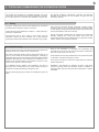
5.2 - Commissioning
Once all (and not just some) of the system devices have passed the
testing procedure, the system can be commissioned;
the system’s technical dossier must be produced and kept for 10
years. It must contain the electrical wiring diagram, a drawing or
photograph of the system, the analysis of the risks and the solutions
adopted to deal with them, the manufacturer’s declaration of con-
formity for all connected devices, the operator’s manual for every
device and the system maintenance plan:
x a dataplate with the details of the automation, the name of
the person who commissioned it, the serial number and year of
construction and the CE marking on the gate or door:
also t a plate specifying the procedure for releasing the system by
hand:
draw up the declaration of conformity, the instructions and
precautions for use for the end user and the system maintenance
plan and consign them to the end user;
ensure that the user has fully understood how to operate the system
in automatic, manual and emergency modes;
the end user must also be informed in writing about any risks and
hazards still present;
WARNING - after detecting an obstacle, the gate or door stops
during its opening travel and automatic closure is disabled; to
restart operation, the user must press the control button or use the
transmitter.
5 - TESTING AND COMMISSIONING THE AUTOMATION SYSTEM
5.1 - Testing
All system components must be tested following the procedures
described in their respective operator’s manuals
ensure that the recommendations in Chapter 1 - Safety Warnings -
have been complied with
check that the gate or door is able to move freely once the
automation system has been released and is well balanced,
meaning that it will remain stationary when released in any position;
check that all connected devices (photocells, sensitive edges,
emergency buttons, etc.) are operating correctly by performing gate
or door opening, closing and stop tests using the connected control
devices (transmitters, buttons or switches);
perform the impact measurements as required by the EN12445
standard, adjusting the control unit’s speed, motor force and
deceleration functions if the measurements do not give the required
results, until the correct setting is obtained.
The system must be tested by a qualied technician, who must
perform the tests required by the relevant standards in relation
to the risks present, to check that the installation complies with
the relevant regulatory requirements, especially the EN12445
standard which species the test methods for gate and door
automation systems.

12
EN
6 - FURTHER DETAILS
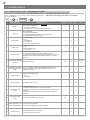
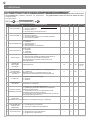
6.1 - Customising the system - ADVANCED SETTINGS
If necessary, users may select the ADVANCED SETTINGS, which
allow modication of the control unit’s advanced parameters.
Proceed as follows:
PARAMETERS DESCRIPTION DEFAULT MIN. MAX. UNIT
1PHOTO 1
Use of PHOTO1 when starting from closed
0 = PHOTO 1 deactivated
1 = PHOTO1 is checked
2 = the gate starts even with PHOTO1 activated
2 0 2
2PHOTO 2
Use of PHOTO2
0 = PHOTO 2 deactivated
1 = enabled during both opening and closing OP/CL
2 =only enabled during opening OP
1 0 2
3PHOTOTEST
Photo-device test
0 = off
1 = PHOTO1 on
2 = PHOTO2 on
3 = PHOTO1 and PHOTO2 on
0 0 3
4EDGE TYPE
Sensitive edge type
0 = off
1 = 8k2 sensitive edge
2 = NC contact
2 0 2
5SAFETY EDGE
Sensitive edge tripping mode
0= only tripped during closure with direction reversal
1 = stops the automation (during both opening and closure) and
retreats from the obstacle (travels short distance in opposite
direction)
0 0 1
6PEDESTRIAN OPENING
LENGHT Pedestrian opening 50 30 100 % (step
of 1)
7
AUTOMATIC CLOSING
FROM PEDESTRIAN
OPEN
Time for automatic closure from pedestrian opening (0=off)
1 to 900 Seconds of delay before automatic closure from
pedestrian opening
0 0 900 s
8FLASH LIGHT
Flashing light output setup
0 = Fix
1 = Flashing
1 0 1
9PRE-FLASHING Pre-ashing time (0 = off) 0 0 20 s
10 COURTESY LIGHT
START
Courtesy light setup
0 = ON at end of operation for courtesy light time
1 = ON if gate not closed + courtesy light duration time at end of
operation
2 = ON if courtesy light timer has not gone out since start of
operation
0 0 2
11 COURTESY LIGHT
TIME Courtesy light duration time (0 = off) 30 0 900 s
12 LIGHT INTENSIVITY AT
END OF MOVEMENT
0 = light off after operation
5 = maximum brightness with motor stopped 2 0 5
13 STOP BUTTON 0 = NC stop button not connected
1 = NC stop button connected 1 0 1
14A ADVANCED
SETTINGS
CAUTION: the parameters may vary with respect to those in the
table below, depending on the motor to be installed.

13
EN
14 DEAD MAN 0 = off
1 = on (safety devices disabled) 0 0 1
15 GATE OPEN
INDICATOR
0 = deactivated
1 = gate open light ON/OFF
2 = gate open light proportional
0 0 2
16 MAINTENANCE Service interval cycle threshold 10 1 200 x 1000
cycles
17 MAINTENANCE FLASH
Enabling of continuous ashing when service is required (only
active with gate closed).
0 = off
1 = on
0 0 1
18 ELECTROLOCK
ACTIVATION
0 = off
Activated for from 1 to 20 seconds when the motors start to open
the gate
2 0 20 s
19 WATER HAMMERING
IN OPENING
From motor M1 closed
0 = off
Motor M1 activated for from 1 to 30 seconds in the closing
direction to ensure that the electric lock releases
0 0 30 s
20 WATER HAMMERING
IN CLOSING
From motor M1 closed
0 = off
Motor M1 activated for from 1 to 30 seconds in the closing
direction to ensure that the electric lock engages
0 0 30 s
21 MOTOR RELEASE AT
STOP
Motor release from limit switch. Useful for lightweight gates
0 = off
1 to 10 release levels (1 = minimum release, 10 = maximum
release)
0 0 10
22 START UP BOOST
High-speed motor start-up. Useful for heavy gates in winter
0 = off
1 = on
0 0 1
23 CLOSING DELAY M 1 Leaf 1 closing delay with gate open
0 = Off
1 = 1 to 180 Seconds On 1 0 180 s
24 ENCODER
1 = Off (use of virtual encoder)
2 = On (use of motor’s physical encoder) 1 1 2
25 ENCODER PULSES 1 to 10 pulses per revolution of the physical encoder (only with 24
set as “2”) 1 1 10
26 DEFAULT Restoring the default values 0 0 1

14
EN
6.2 - RX4X RECEIVER
If necessary, users may select the RX4X RECEIVER MENU, used
to manage the parameters relating to the radio unit.
Proceed as follows:
ADDING A TX USING THE DISPLAY
This procedure allows one or more transmitters to be memorised in the receiver.
(WARNING: if there is not already at least one transmitter in the memory, the rst transmitter entered will establish the type of code -
rolling code or xed code).
1. Access the menu
2. Select the type of channel in which the button is to be saved (CHANNEL 1= step by step; 2= pedestrian opening; 3= open; 4= lights
on/off; 5= memorisation of all 4 codes with preset functions as specied above). Press V to conrm.
3. Press the button of the TX to be memorised.
4. After the button is pressed, the display will show: TRANSMITTER MEMORISED.
5. To add another code, start the procedure again from point 2. To quit the menu, press “X”.
The “X” button is effective at any point in the procedure.
If no commands are given for 10 seconds, the receiver automatically quits the memorisation mode.
DELETING A TX USING THE DISPLAY
This procedure allows a radio code to be deleted from the memory of the RX4X receiver using the transmitter memorised.
1. Access the menu
2. Press the button of the TX to be deleted when prompted.
3. After the button is pressed, the display will show: TRANSMITTER DELETED.
4. When the code has been deleted, the display will show the memory position it was cleared from.
5. To add another code, start the procedure again from point 2.
To quit the menu, press “X”. The “X” button is effective at any point in the procedure.
If no commands are given for 10 seconds, the receiver automatically quits the memorisation mode.
CLEARING THE MEMORY OF THE RX4X RECEIVER
This procedure is used to clear the entire memory of the receiver.
1. Access the menu
2. Conrm the request by pressing “V” or exit using “X”.
3. On conrmation, the display will show: MEMORY DELETED.
MEMORY LOCK/UNLOCK
This procedure is used to lock or unlock the memory of the RX4X receiver.
1. Access the menu
0=OFF memory unlocked
1= ON memory locked
READING THE RECEIVER MEMORY
This procedure is used to view the radio codes present in the memory of the RX4X receiver.
1. Access the menu
2. Use ▲ and ▼ to scroll through the codes in the memory. The number of the transmitter in the memory, the radio
code saved and the relative button and channel will appear on the rst line of the display, while the second line will
indicate that the code can be deleted, conrming with V.
3. To quit the menu, press “X”.
The “X” button is effective at any point in the procedure.
ADD TX Allows a new code to be memorised in the receiver
DELETE TX Allows deletion of a code from the receiver
DELETE ALL Clears the receiver’s entire memory
READ MEMORY Displays the codes in the memory
MEMORY LOCK/UNLOCK Unlocks or locks the receiver’s memory
14A RX4X
RX4X
RX4X
RX4X
RX4X
RX4X
ADD TX
DELETE TX
CLEAR ALL
MEMORY
LOCK/UNLOCK
READ MEMORY
AB
CD
M = PRESET
FUNCTIONS
N.B. if the receiver is blocked by means of the XR MANAGER device, refer to the user manual of the latter.

15
EN
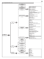
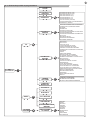
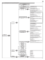
6.3 - Programmer ow chart
KEY
AUTOMATION
14A
QUICK
PROGRAMMING
SELECT
LANGUAGE
ADD TX
FULL
PROGRAMMING
DELETE TX
BASIC SETTINGS
ADVANCED
SETTINGS
NIGHT LIGHTS
MANUAL
COMMANDS
DIAGNOSTIC
DELETE ALL
READ MEMORY
MEMORY
LOCK/UNLOCK
MOTOR 1 CURRENT (mA)
MOTOR 2 CURRENT (mA)
MOTOR 1 POSITION (%)
MOTOR 2 POSITION (%)
MOTOR 1 SPEED (%)
MOTOR 2 SPEED (%)
TOTAL CYCLES (CYCLES)
CYCLES LEFT BEFORE SERVICE
SOFTWARE VERSION
AUTOMATIC CLOSING TIME
AUTOMATIC CLOSING AFTER TRANSIT
SENSITIVITY
OPENING SPEED
SLOW DOWN OPENING SPEED
CLOSING SPEED
SLOW DOWN CLOSING SPEED
STEP BY STEP
MOTOR 2 DELAY
SLOW DOWN LENGTH
ENERGY SAVING
PHOTO 1
PHOTO 2
PHOTOTEST
EDGE TYPE
SAFETY EDGE
PEDESTRIAN OPENING LENGTH
AUTOMATIC CLOSING PEDESTRIAN OPEN
FLASH LIGHT
PRE-FLASHING
COURTESY LIGHT START
COURTESY LIGHT TIME
LIGHT INTENSIVITY AT END OF MOVEMENT
STOP BUTTON
DEAD MAN
GATE OPEN INDICATOR
MAINTENANCE
MAINTENANCE FLASH
ELECTROLOCK ACTIVATION
WATER HAMMERING IN OPENING
WATER HAMMERING IN CLOSING
MOTOR RELEASE AT STOP
START UP BOOST
CLOSING DELAY M 1
ENCODER
ENCODER PULSES
DEFAULT
AUTOMATIC LIGHT
LIGHT INTENSIVITY
EXTERNAL LIGHT LEVEL
ENGLISH
CESKY
DEUTSCH
ESPANOL
FRANCAIS
ITALIANO
MAGYAR
NEDERLANDS
POLSKI
PORTUGUES
SLOVENSCINA
DISPLAY
OPTIONS
RX4X
▲ ▼
▲ ▼
▲ ▼
▲ ▼
▲ ▼
▲ ▼
▲ ▼
▲ ▼
▲ ▼
▲ ▼
▲ ▼
▲ ▼

16
EN
Magifer produces systems for the automation of gates, garage do-
ors, automatic doors, roller blinds and car-park and road barriers.
However, Magifer is not the manufacturer of your complete auto-
mation system, which is the outcome of the analysis, assessment,
choice of materials and installation work of your chosen installer.
Every automation system is unique, and only your installer has the
experience and skill required to produce a safe, reliable, durable
system tailored to your needs, and above all that complies with the
relevant regulatory standards. Although your automation system
complies with the regulation safety level, this does not rule out the
presence of “residual risk”, meaning the possibility that hazards may
occur, usually due to reckless or even incorrect use. We would the-
refore like to give you some advice for the correct use of the system:
• before using the automation system for the rst time, have the
installer explain the potential causes of residual risks to you.
• keep the manual for future reference, and pass it on to any new
owner of the automation system;
• reckless use and misuse of the automation system may make it
dangerous: do not operate the automation system with people, ani-
mal or objects within its range of action;
• a properly designed automation system has a high level of safety,
since its sensor systems prevent it from moving with people or ob-
stacles present so that its operation is always predictable and safe.
However, as a precaution children should not be allowed to play clo-
se to the automation system, and to prevent involuntary activation,
remote controls must not be left within their reach.
• as soon as any system malfunction is noticed, disconnect the
electricity supply and perform the manual release procedure. Never
attempt repairs on your own; call in your installation engineer. In
the meantime the door or gate can be operated without automation
once the geared motor has been released using the release key
supplied with the system. In the event of safety devices out of ser-
vice arrange for repairs to the automation immediately;
• in the event of a breakdown or power supply failure: while waiting
for the engineer to come (or for the power to be restored if your
system is not equipped with buffer batteries), the automated system
can be used just like any non-automated installation. To do this, the
manual release procedure must be carried out;
• manual release and operation: rst bear in mind that the release
procedure can only be carried out with the door or gate stationary.
• Maintenance: Like any machine, your automation system needs
regular periodic maintenance to ensure its long life and total safety.
Arrange a periodic maintenance schedule with your installation en-
gineer. Magifer recommends that maintenance checks should be
carried out every six months for normal domestic use, but this inter-
val may vary depending on the level of use. Any inspection, main-
tenance or repair work must only be carried out by qualied staff.
• Never modify the automation system or its programming and setup
parameters: this is the responsibility of your installation engineer.
• Testing, routine maintenance and any repairs must be recorded by
the person who performs them and the documents must be conser-
ved by the system’s owner.
The only procedures you are capable of, and which you are recom-
mended to perform, are cleaning of the photocell glass and removal
of any leaves or stones that may obstruct the automation system.
To prevent anyone from activating the gate or door, release the au-
tomation system before starting. Clean only with a cloth dipped in
a little water.
• At the end of its useful life, the automation system must be dispo-
sed of by qualied personnel, and the materials must be recycled or
disposed of in compliance with the legislation locally in force.
If after some time your transmitter seems to have become less ef-
fective, or stops operating completely, the battery may be at (de-
pending on the level of use, this may take from several months up
to more than a year). You will realise this because the transmission
conrmation light does not come on, or only lights up for a very
short time.
Batteries contain pollutants: do not dispose of them with normal wa-
ste but follow the methods specied by the local regulations.
Thank you for choosing Magifer; please visit our Internet site www.
magifer.com for further information.
7 - INSTRUCTIONS AND WARNINGS FOR THE END USER

17
EN
NOTES

18
FR
1
2
3
4
5
6
7
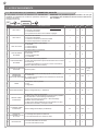
Consignes de sécurité
2.1
2.2
2.3
2.4
4.1
4.2
4.3
4.4
4.5
4.6
4.7
4.8
6.1
6.2
6.3
5.1
5.2
Présentation du produit
Description de la logique de commande
Description des branchements
Modèles et caractéristiques techniques
Liste des câbles nécessaires
Vérications préalables
Installation du produit
Branchements électriques
Utilisation du programmateur avec afcheur
Autoapprentissage de la course
Actionnement de l’automatisme
par programmateur avec afcheur
Actionnement de l’automatisme
par récepteur
Diagnostic
Personnalisation de l’installation -
PARAMETRES DE BASE
LUMIERE NOCTURNE
Approfondissements
Personnalisation de l’installation -
PARAMETRES AVANCÉS
RÉCEPTEUR RX4X
Schéma de procédé du programmateur
Réception et mise en service
Réception
Mise en service
Instructions et avertissements
destinés à l’utilisateur nal
page 19
page 20
page 20
page 20
page 20
page 21
page 21
page 22
page 22
page 23
page 24
page 24
page 24
page 25
page 25
page 26
page 27
page 27
page 27
page 28
page 28
page 30
page 31
page 32
TABLE DES MATIÈRES

19
FR
1 - CONSIGNES DE SÉCURITÉ
ATTENTION – INSTRUCTIONS ORIGINALES – importantes consi-
gnes de sécurité. Il est important, pour la sécurité des personnes,
de respecter les consignes de sécurité suivantes. Conserver ces
instructions.
Lire attentivement les instructions avant d’effectuer l’installation.
La conception et la fabrication des dispositifs qui composent le
produit et les informations contenues dans ce guide respectent
les normes de sécurité en vigueur. Néanmoins, une installation et
une programmation erronées peuvent causer de graves blessu-
res aux personnes qui exécutent le travail et à celles qui utilise-
ront l’installation. C’est pourquoi il est important, durant l’installa-
tion, de suivre scrupuleusement toutes les instructions fournies
dans ce guide.
Ne pas effectuer l’installation en cas de doute, de quelque nature
que ce soit, et, au besoin, demander des éclaircissements au service
après-vente de Magifer.
Pour la législation européenne, la réalisation d’une porte ou d’un
portail automatique doit respecter les normes prévues par la di-
rective 2006/42/CE (directive Machines) et, en particulier, les nor-
mes EN 12445, EN 12453, EN 12635 et EN 13241-1, qui permettent
de déclarer la conformité de l’automatisme.
C’est pourquoi le branchement dénitif de l’automatisme au réseau
électrique, la réception de l’installation, sa mise en service et la main-
tenance périodique doivent être conés à du personnel qualié et
spécialisé qui interviendra selon les instructions fournies dans la sec-
tion « Réception et mise en service de l’automatisme ».
De plus, il devra se charger de procéder aux essais prévus en fonction
des risques présents et vérier le respect de toutes les prescriptions
des lois, normes et règlements : en particulier, le respect de toutes les
exigences de la norme EN 12445 qui dénit les méthodes d’essai pour
la vérication des automatismes pour portes et portails.
ATTENTION - Avant de commencer l’installation, effectuer les
analyses et vérications suivantes:
vérier que chacun des dispositifs destinés à l’automatisme est adapté
à l’installation à réaliser. À ce sujet, contrôler tout particulièrement les
données indiquées dans le chapitre « Caractéristiques techniques ».
Ne pas effectuer l’installation si ne serait-ce qu’un seul de ces disposi-
tifs n’est pas adapté à ce type d’utilisation;
vérier que les dispositifs achetés sont sufsants pour garantir la sécu-
rité de l’installation et son bon fonctionnement;
effectuer l’analyse des risques, qui doit aussi comprendre la liste des
exigences essentielles de sécurité contenues dans l’annexe I de la di-
rective Machines, en indiquant les solutions adoptées. L’analyse des
risques est l’un des documents qui constituent le dossier technique
de l’automatisme. Ce dernier doit être rédigé par un installateur pro-
fessionnel.
Compte tenu des situations de risque qui peuvent se présenter
durant les phases d’installation et d’utilisation du produit, il est
nécessaire d’installer l’automatisme en respectant les consignes
suivantes :
ne pas apporter de modications à une quelconque partie de l’auto-
matisme, en dehors de celles qui sont prévues dans ce guide. Ce type
d’interventions ne peut que causer des problèmes de fonctionnement.
Le constructeur décline toute responsabilité en cas de dommages déri-
vant de produits modiés de manière arbitraire ;
il faut faire en sorte que les pièces des composants de l’automatisme
ne soient jamais plongées dans l’eau ni dans d’autres substances li-
quides. Durant l’installation, éviter que des liquides puissent pénétrer à
l’intérieur des dispositifs présents;
si le câble d’alimentation est détérioré, il doit être remplacé par le con-
structeur, par son service après-vente ou, dans tous les cas, par une
personne ayant une qualication similaire, de manière à prévenir tout
risque éventuel;
si des substances liquides pénètrent à l’intérieur des pièces des com-
posants de l’automatisme, débrancher immédiatement l’alimentation
électrique et s’adresser au service après-vente Magifer. L’utilisation de
l’automatisme dans ces conditions peut être source de danger;
ne pas mettre les différents composants de l’automatisme à proximité
de sources de chaleur et ne pas les exposer à des ammes libres. Ces
actions peuvent les endommager et causer des problèmes de fonction-
nement, un incendie ou des dangers;
toutes les opérations qui nécessitent l’ouverture de la coque de pro-
tection des différents composants de l’automatisme doivent s’effectuer
avec la logique de commande débranchée de l’alimentation électrique.
Si le dispositif de mise hors tension ne peut pas être surveillé, il faut
poser dessus un écriteau indiquant : « MAINTENANCE EN COURS »;
tous les dispositifs doivent être raccordés à une ligne d’alimentation
électrique avec mise à la terre de sécurité ;
le produit ne peut pas être considéré comme un système de protection
efcace contre l’intrusion. Si vous souhaitez vous protéger efcace-
ment, il faut intégrer d’autres dispositifs à l’automatisme;
le produit ne peut être utilisé qu’après les opérations de « mise en
service » de l’automatisme, comme cela est prévu dans le paragraphe
« Réception et mise en service de l’automatisme »;
prévoir dans le réseau d’alimentation de l’installation un dispositif de
disjonction avec une distance d’ouverture des contacts qui garantisse
la disjonction complète dans les conditions prévues par la catégorie de
surtension III;
pour le raccordement de tubes rigides et exibles ou de passe-câ-
bles, utiliser des raccords conformes à l’indice de protection IP55 ou
supérieur;
l’installation électrique en amont de l’automatisme doit être conforme
aux normes en vigueur et être réalisée dans les règles de l’art ;
il est conseillé d’utiliser un bouton d’urgence à installer à proximité de
l’automatisme (raccordé à l’entrée STOP de la carte de commande) de
manière à pouvoir arrêter immédiatement le portail ou la porte en cas
de danger;
ce dispositif n’est pas destiné à être utilisé par des personnes (y com-
pris les enfants) dont les capacités physiques, sensorielles ou menta-
les sont limitées ou qui manquent d’expérience ou de connaissance, à
moins qu’elles aient pu bénécier, par le biais d’une personne respon-
sable de leur sécurité, d’une surveillance ou d’instructions relatives à
l’utilisation du dispositif;
si le câble d’alimentation est détérioré, il doit être remplacé par le con-
structeur, par son service après-vente ou, dans tous les cas, par une
personne ayant une qualication similaire, de manière à prévenir tout
risque éventuel;
avant d’actionner l’automatisme, s’assurer que personne ne se trouve
à proximité;
avant d’effectuer une quelconque opération de nettoyage et de mainte-
nance de l’automatisme, le débrancher du réseau électrique;
les enfants doivent être surveillés an de s’assurer qu’ils ne jouent pas
avec l’appareil.
ATTENTION - Les matériaux d’emballage de tous les composants
de l’automatisme doivent être éliminés conformément à la norme
locale en vigueur.
ATTENTION - Les données et les informations fournies dans ce
guide peuvent être modiées par Magifer à tout moment et sans
obligation de préavis.

20
FR
2.1 - Description de la logique de commande
La logique de commande 14A est un système de contrôle modulaire
pour les moteurs Key Automation pour l’ouverture et la fermeture
électrique de portails battants, coulissants, barrières et portes de garage.
La logique de commande 14A est équipée d’un programmateur avec
afcheur (en option) qui permet d’effectuer facilement les opérations
2.2 - Description des branchements
1- Branchement alimentation logique de commande 24 Vca
2- Siège module de puissance M1
3- Siège module de puissance M2
4- Connecteur programmateur avec afcheur
5- Logement récepteur RX4X/RX4U
6- Touche de commande PAS À PAS incorporée
7- Branchements antenne extérieure
8- LED indication état des entrées
9- Bornier branchement accessoires/entrées
10- Fusibles de protection 2,5AT
11- Branchement batteries
ATTENTION :
le module de puissance
PO24 doit être
connecté/déconnecté
impérativement avec la logique
de commande non alimentée!
2.3 - Modèles et caractéristiques techniques
de programmation et de surveiller constamment l’état de la logique
de commande ; de plus, la structure en menus simplie les
paramétrages des temps de travail et des logiques de fonctionnement.
Le menu de l’afcheur est multilingue.
Toute autre utilisation impropre de la logique de commande est interdite.
2 - PRÉSENTATION DU PRODUIT
CODE DESCRIPTION
900MA24 Module logique associable à 1 ou 2 modules de puissance PO24 pour le contrôle d’1 ou 2 moteurs 24V, pour
portails battants, coulissants, barrières et portes de garage
SBS
M1
M2
COM
PED
OPEN
CLOSE
SBS
NEG
PH-POW
PH1
PH2
COM
FLASH
LED
SEN
SHIELD
ANT
COM
STOP
EDGE
EDGE
COM
ELEC
COM
IND
STOP
EDGE
PH1
PH2
PED
OPEN
CLOSE
SBS
POWER
SUPPLY
23
4
6
5
78
9
10
11
1
- Alimentation protégée contre les courts-circuits à l’intérieur de la logique
de commande, sur les moteurs et sur les accessoires raccordés.
- Détection des obstacles par capteur de courant.
- Dispositif anti-écrasement.
- Apprentissage automatique des temps de fonctionnement.
- Ralentissements programmables en ouverture et en fermeture.
- Désactivation des entrées de sécurité par logiciel.
- Tableau électrique avec logique de commande à microprocesseur.
BATTERIES
(ACCESSOIRE)
Page is loading ...
Page is loading ...
Page is loading ...
Page is loading ...
Page is loading ...
Page is loading ...
Page is loading ...
Page is loading ...
Page is loading ...
Page is loading ...
Page is loading ...
Page is loading ...
Page is loading ...
Page is loading ...
Page is loading ...
Page is loading ...
Page is loading ...
Page is loading ...
Page is loading ...
Page is loading ...
Page is loading ...
Page is loading ...
Page is loading ...
Page is loading ...
Page is loading ...
Page is loading ...
Page is loading ...
Page is loading ...
Page is loading ...
Page is loading ...
Page is loading ...
Page is loading ...
-
 1
1
-
 2
2
-
 3
3
-
 4
4
-
 5
5
-
 6
6
-
 7
7
-
 8
8
-
 9
9
-
 10
10
-
 11
11
-
 12
12
-
 13
13
-
 14
14
-
 15
15
-
 16
16
-
 17
17
-
 18
18
-
 19
19
-
 20
20
-
 21
21
-
 22
22
-
 23
23
-
 24
24
-
 25
25
-
 26
26
-
 27
27
-
 28
28
-
 29
29
-
 30
30
-
 31
31
-
 32
32
-
 33
33
-
 34
34
-
 35
35
-
 36
36
-
 37
37
-
 38
38
-
 39
39
-
 40
40
-
 41
41
-
 42
42
-
 43
43
-
 44
44
-
 45
45
-
 46
46
-
 47
47
-
 48
48
-
 49
49
-
 50
50
-
 51
51
-
 52
52


Ask a question and I''ll find the answer in the document
Finding information in a document is now easier with AI
in other languages
Related papers


Other documents
-
Key Gates 14A Owner's manual
-
Marantec CBX20324 Owner's manual
-
-
-
-
Key Gates CT102 User manual
-
 SCS Sentinel MCO0039 Owner's manual
-
 SCS Sentinel MBA0004 Owner's manual
-
 SCS Sentinel MBA0001 Owner's manual
-
 SCS Sentinel MCO0035 Owner's manual


