Page is loading ...

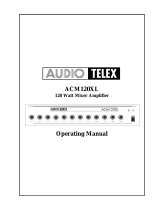
TX6000
6 Channel Mic/Line Mixer
Operating Manual
ON 21 15 9 6 3 0 +3dB
CH 1 CH 2 CH 3 CH 4 CH 5 CH 6 BASS TREBLE MASTER HEADPHONE
TX 6000
222222
33
2
111111 44 1
000000 550
888888 338
10 10 10 10 10 10
55
10
777777 227
666666 116
999999 449
555555 005
444444
4
333333 223

Product Description
The TX6000 is a 6 channel audio mixer that operates from 240 VAC @ 50 Hz (115 VAC @ 60 Hz with factory
modification) or 24 VDC via an external battery supply. The TX6000 is 1 standard rack unit high (44mm) and has a
standard rack width of 482mm. For table mounting, rubber feet are supplied but these can be removed if rack mounting
is intended. Six dual purpose inputs consisting of XLR balanced mic inputs and dual RCA aux/line level inputs are
included. Channel 6 has a less sensitive aux/line level input to enable it to accept a CD player or similar high level inputs.
TX6000, 6 Channel Mic/Line Mixer
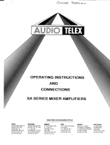
Front Panel Features
Input Level Controls
The 6 dual mic/line input controls are marked Ch 1 through Ch 6 and should be adjusted to provide the required mix
level for each individual channel. Start with the controls set to level 0 and turn the controls slowly clockwise until the
desired mix for each channel is obtained.
Bass Control
The Bass control is part of a 2 band equalisation system within the TX6000. The Bass control allows the user to increase
or decrease the amount of bass in the system. The control allows for 12dB of cut or boost at 100Hz. If no bass cut or
boost is required, the control should be left in the centre (0) position.
Treble Control
The Treble control is part of a 2 band equalisation system within the TX6000. The Treble control allows the user to
increase or decrease the amount of treble in the system. The control allows for 9dB of cut or boost at 10kHz. Generally,
a small increase of the treble control makes a system sound ‘brighter’. If no treble cut or boost is required, the control
should be left in the centre (0) position.
Master Control
The master control sets the overall output level of the TX6000. It is used in conjunction with the input level controls.
When setting up levels, please ensure that proper gain structure practices are followed. In other words, it is not advisable
to run the input channels at 10 and the output level at 1. Instead, aim to keep all of the input controls and the master
control at around the same level.
Headphone Output Socket
A 1/4” (6.35mm) socket is provided for the connection of monitor headphones. The output level to the headphones is a
nominal 3.5 volts @ 600 ohms and is connected before the master output level control so adjusting the output level
control will not effect the headphone output level.
Power Switch & “On” LED
The black rocker switch on the right hand side of the front panel is used to switch the mixer on and off. The ‘up’ position
is on. When the amplifier is connected to an appropriate AC power source and is switched on, the blue “on” LED
(located on the left side of the LED display) will illuminate.
ON 21 15 9 6 3 0 +3dB
CH 1 CH 2 CH 3 CH 4 CH 5 CH 6 BASS TREBLE MASTER HEADPHONE
TX 6000
222222
33
2
111111 44 1
000000 550
888888 338
10 10 10 10 10 10
55
10
777777 227
666666
11
6
999999 449
555555 005
444444
4
333333 223

LED Display VU Meter
The first LED indicates whether the unit is switched on. The remainder of the LED display is set in decibel graduations
from -21 dB to +3 dB and indicates the level at the output of the mixer. For normal operation the LED’s should glow green
and modulate with level variations from the input program. If the LED’s are consistently indicating red, then the mixer is
being overdriven which will result in distortion. Avoid operating the mixer with the red LED’s illuminated.
Rear Panel Features
AC Power Inlet
The 3 pin IEC power inlet is located on the left side of the rear panel and accepts a standard mains power lead fitted with
an IEC connector. The operating voltage is 240 VAC @ 50 Hz (115 VAC @ 60 Hz with factory modification). The AC
power voltage is not externally user adjustable but is factory preset. The inlet is equipped with an inbuilt AC fuse holder
fitted with a 0.5 amp slow blow fuse plus one spare. Power consumption is 7 VA.
! Please ensure that the mains power cord is disconnected before attempting to check or replace this fuse.
24 Volt DC Power Source Connection
Located to the top right of the IEC power inlet is a 2.1mm DC power socket which provides for the connection of an
external 24 VDC battery. This is ideal for systems where battery backup is required or for applications where mains
power is not available. The centre terminal post or pin is for connection to the positive (+) terminal. The sleeve is for
connection to the negative (-) terminal.
Screw Terminals
The five screw terminals located on the rear panel allow for the connection of an optional tone module. The ATC5488
tone module is equipped with 4 tones and a common. The optional module would normally be fitted inside the mixer
with the activation wires and common all connected to the screw terminals for easy external activation via switches or
third party timers. The screw terminals are not connected internally when supplied from the factory.
Output Connector
The rear panel of the TX6000 includes a male XLR output connector. The output is an active balanced isolated output
for connection to a power amplifier. The maximum output is 1.5V RMS. Pin connections are Pin 1 = Earth. Pin 2 =
Active Positive (+). Pin 3 = Active Negative (-). Note: If an unbalanced output is required, use a 600 Ohm matching
transformer or use only Pin 2 and Earth. Do not short any of the active outputs to earth.
Tape Output
Two RCA output connectors are included on the rear panel. These provide a line level record output from the mixer.
The tape output provides a maximum of 700mV into 10K ohms making it ideal for connection to most standard tape
recorders. This output is sourced before the master gain control and as such the tape output level is not influenced by the
operation of the master gain control.
Microphone Inputs
The TX6000 includes six female XLR inputs which accept 200 ohm balanced or unbalanced microphones. Pin connec-
tions are Pin 1 = Earth. Pin 2 = Active Positive (+). Pin 3 = Active Negative (-).
MIC 5 MIC 4 MIC 3 MIC 1MIC 2LINE 6MIC 6 LINE 5 LINE 4 LINE 3 LINE 2 LINE 1TAPE OUTOUTPUT
ENGINEERED BY
AUDIO TELEX COMMUNICATIONS PTY LTD SYDNEY AUSTRALIA
+24V

Phantom Power
The microphone inputs on the TX6000 all provide +18v DC phantom power which is required for electret microphones.If
desired, phantom power can be defeated via an internal jumper which is located on the output board near the line output
XLR socket on the rear panel (position X4 on the output board). The default setting is with the link in the ‘on’ position,
shorting the centre pin and the pin closest to the rear of the TX6000. To turn phantom power off, move the link to short
the centre pin and the pin closest to the front of the TX6000. Note: It is necessary to disconnect the power cord and
remove the lid from the mixer before operating this switch.
Optional Accessories
Note: The installation of some of the following optional accessories involves access to the inside of the mixer. Installa-
tion should only be attempted by a qualified technician. Always turn off the AC power and remove the AC power cord
before attempting to access the inside of the mixer.
Tone Generator Module
An optional ATC5488 4 tone generator board is available for the TX6000. This internally mounted PCB can be easily
fitted and plugs directly into a socket provided on the pre-amp circuit board inside the TX6000. The socket is located on
the front board behind the input 5 level control. Please follow the instructions supplied with the tone generator. When
any tone from the ATC5488 is activated (via contact closure) all inputs will automatically mute except for input 1. Tones
available on the ATC5488 tone generator board are:
Evacuation Tone (to Australian Standard AS2220.1.2)
Alert Tone (to Australian Standard AS2220.1.2)
Bell Tone
Pre Announce Chime
Muting Modules
Two optional VOX (signal activated) muting modules are available for the TX6000. The TX3010 mutes channels 2-6
from input 1 while the TX3014 is a dual level muting module which mutes channels 2-6 from input 1 and 3-6 from input
2. Both modules plug into a socket provided on the pre-amp circuit board inside the TX6000. The socket is located
directly behind the input 1 level control.
TX3010 Muting Module: Provides muting from channel 1 only. When activated, all other channels are muted
TX3014 Muting Module: Provides dual priority muting. Channel 1 mutes 2-6. Channel 2 mutes 3-6.
Fuse Sizes TX6000 Mixer
Mains 240 VAC: 0.5 Amperes Slow Blow
Line Inputs
The TX6000 includes six dual RCA inputs for unbalanced line or aux devices such as tape recorders, video players,
tuners etc. Channel 6 has been designed to accept higher level line inputs such as CD players. When using a CD player
with the TX6000, please ensure it is plugged into the channel 6 line input. Dual RCA connectors are provided to allow
for the simple connection of domestic stereo devices such as tape desks and CD players. Both the left and right outputs
from these devices can be connected to the dual RCA’s and will be summed to mono within the TX6000.
Note: Each input of the TX6000 has both a microphone and line connection. Please note that only one of these (on each
channel) should be used at the same time.

1. Save the carton and packing material even if the equip-
ment has arrived in good condition. Should you ever
need to ship the unit, use only the original factory pack-
ing.
2. Read all documentation before operating your equip-
ment. Retain all documentation for future reference.
3. Follow all instructions printed on unit chassis for
proper operation.
4. Do not spill water or other liquids into or on the unit,
or operate the unit while standing in liquid.
5. Make sure power outlets conform to the power re-
quirements listed on the back of the unit.
6. Do not use the unit if the electrical power cord is
frayed or broken. The power supply cords should be
routed so that they are not likely to be walked on or
pinched by items placed upon or against them, paying
particular attention to cords and plugs, convenience re-
ceptacles, and the point where they exit from the
appliance.
7. Always operate the unit with the AC ground wire
connected to the electrical system ground. Precautions
should be taken so that the means of grounding of a
piece of equipment is not defeated.
8. Mains voltage must be correct and the same as that
printed on the rear of the unit. Damage caused by
connection to improper AC voltage is not covered by
any warranty.
9. Have gain controls on amplifiers turned down during
power-up to prevent speaker damage if there are high
signal levels at the inputs.
10. Power down & disconnect units from mains voltage
before making connections.
11. Never hold a power switch in the “ON” position if it
won’t stay there itself!
12. Do not use the unit near stoves, heat registers, ra-
diators, or other heat producing devices.
13. Do not block fan intake or exhaust ports. Do not
operate equipment on a surface or in an environment
which may impede the normal flow of air around the
unit, such as a bed, rug, weathersheet, carpet, or com-
pletely enclosed rack. If the unit is used in an extremely
dusty or smoky environment, the unit should be peri-
odically “blown free” of foreign matter.
14. Do not remove the cover. Removing the cover will
expose you to potentially dangerous voltages. There
are no user serviceable parts inside.
15. Do not drive the inputs with a signal level greater
than that required to drive equipment to full output.
16. Do not connect the inputs / outputs of amplifiers
or consoles to any other voltage source, such as a
battery, mains source, or power supply, regardless of
whether the amplifier or console is turned on or off.
17. Do not run the output of any amplifier channel
back into another channel’s input. Do not parallel- or
series-connect an amplifier output with any other
amplifier output.
Audio Telex Communications Pty Ltd is not respon-
sible for damage to loudspeakers for any reason.
18. Do not ground any red (“hot”) terminal. Never
connect a “hot” (red) output to ground or to another
“hot” (red) output!
19. Non-use periods. The power cord of equipment
should be unplugged from the outlet when left un-
used for a long period of time.
20. Service Information Equipment should be serviced
by qualified service personnel when:
A. The power supply cord or the plug has been
damaged.
B. Objects have fallen, or liquid has been spilled into
the equipment
C. The equipment has been exposed to rain
D. The equipment does not appear to operate normally,
or exhibits a marked change in performance
E. The equipment has been dropped, or the enclosure
damaged.
Important Safety Information

Engineered by Audio Telex Communications Pty Ltd, Sydney, Australia
A.B.N. 78 001 345 482 Inc in NSW
Sydney (NSW & ACT Sales)
Private Bag 149, Silverwater NSW 1811
149 Beaconsfield Street, Silverwater NSW 2128
Ph: (02) 9647 1411
Fax: (02) 9648 3698
E-mail: [email protected]
Melbourne (Vic & Tas Sales)
P.O. Box 131, Blackburn South VIC 3130
22/277 Middleborough Road, Box Hill VIC 3128
Ph: (03) 9890 7477
Fax: (03) 9890 7977
E-mail: [email protected]
Brisbane (Qld Sales)
P.O. Box 871, Fortitude Valley QLD 4006
42 Commerical Road, Fortitude Valley QLD 4006
Ph: (07) 3852 1312
Fax: (07) 3252 1237
E-mail: [email protected]
Adelaide (SA & NT Sales)
P.O. Box 157, Hindmarsh SA 5001
31 Walsh Street, Thebarton SA 5031
Ph: (08) 8352 4444
Fax: (08) 8352 4488
E-mail: [email protected]
Perth (WA Sales)
P.O. Box 404, North Perth WA 6906
299 Fitzgerald Street, West Perth WA 6005
Ph: (08) 9228 4222
Fax: (08) 9228 4233
E-mail: [email protected]
Auckland (NZ Sales)
P.O. Box 512, Albany 1331
Unit B, 11 Piermark Drive, Albany 1331
Ph: (09) 415 9426
Fax: (09) 415 9894
E-mail: [email protected]
Export Sales & Corporate Head Office
Private Bag 149, Silverwater NSW 1811
149 Beaconsfield Street, Silverwater NSW 2128
Australia
Ph: 61-2- 9647 1411
Fax: 61-2-9748 2537
E-mail: [email protected]
www.audiotelex.com.au
/