DIGITAL HOME THEATER SYSTEM
Printed in China
WG84200
YHT -270
Subwoofer (SW-P270) 4
Surround speakers (NX-E270) 3
Center speaker (NX-C270) 2
Front speakers (NX-E270) 1
Receiver (HTR-5930)
Major specifications for speakers
When placing the speaker on top of the TV rack, etc., attach
the provided fasteners at two points on the bottom of the
speaker and on the top of the TV.
Notes
• Do not place the center speaker on top of a TV whose area is
smaller than the bottom of the speaker. If placed, the speaker
may fall and cause injury.
• Do not place the center speaker on top of a TV if the top is
inclined.
• Do not touch the adhesive surface after peeling off the seal, as
this will waken its adhesive strength.
•Thoroughly wipe clean the surface where the fastener is to be
applied. Note that adhesive strength is weakened if the surface is
dirty, oily or wet and that this may cause the center speaker to
fall.
1 Fasten two screws into a firm wall or wall support at
the interval shown below.
Mounting the speakers on the wall
You can mount the front and/or surround speakers on a wall. To mount them on a wall, use the holes of the
brackets attached on the back panels of the speakers.
2 Hang the speaker by mounting the holes on the
protruding screws.
Make sure that the screws are securely affixed by the
narrow parts of the holes.
Caution
• Each speaker weighs 0.8 kg (1.76 lbs).
• Do not mount the speakers on thin plywood or a wall composed of a soft surface material. If mounted, the
screws may pull out of the flimsy surface and the speakers may fall. This may damage the speakers or cause
personal injury.
• Do not affix the speakers to a wall using nails, adhesives, or any other unstable hardware. Long-term use and
vibrations may cause the speakers to fall.
•To avoid accidents resulting from tripping over loose speaker cables, fix the cables to the wall.
• Select an appropriate position on the wall to mount the speaker so that no one will injure his/her head or face.
Installing the speakers on commercially available speaker stands
It is recommended to place the subwoofer on the outside
of either the right or the left front speaker (figure A). The
placement shown in figure B is also possible, however, if
the subwoofer is placed directly facing the wall, the bass
sound may lessen because the sound from the subwoofer
and the sound reflected by the wall may cancel out each
other. To prevent this from happening, face the subwoofer
obliquely to the wall.
AB
Use the non-skid pads
Attach the provided non-skid pads at the four corners on
the bottom of the subwoofer to prevent the subwoofer
from moving by vibrations, etc.
Thank you for selecting this YAMAHA YHT-270.
1 About This system
(HTR-5930: refer to the “HTR-5930 Owner’s manual” for specifications and safety cautions.)
2 About speakers
Center speaker
Front and surround speakers
70 mm
(2-3/4”)
Holes
Minimum
20 mm (25/32”)
10 mm
(2-3/4”)
When you install the speakers on commercially
available speaker stands, you need to attach the
brackets (option) to the bottom of the speakers using
screws (option).
Subwoofer
3 Placing the speakers
1
3
2
4
Speaker layout
Placing the speakers
When placing the speakers on a flat surface,
attach the included non-skid pads to the corner on
the bottom of the speakers. This prevents the
speakers from sliding.
Non-skid pad
2006 All ri
hts reserved.
SYSTEM CONNECTION GUIDE
Supplied accessories
Peel off
the seal
Before making connections, place all speakers in their respective positions. The positioning of the
speakers is important because it controls the whole sound quality of your audio system.
Place the speakers depending on your listening position by following the instructions below.
Front R
Front L
Surround L
Surround R
: Subwoofer
: Front speaker
Bracket (AAX34790)
Screw (AAX12390)
60 mm (2-3/8”)
Insert only M4
screws through the
outside holes.
*Please use the speaker stand that fits with this size.
Speaker cable
4 m (157-1/2”) x 3
for Center/Front
speakers
Speaker cable
10 m (393-11/16”) x 2
for Surround
speakers
Fastener x 2 set
for NS-C270
Non-skid pad
8 pcs x 2 set
For NS-E270
For NS-E270 / NS-C270
Subwoofer cable
4 m (157-1/2”) x 1
Non-skid pad
4 pcs x 1 set
For SW-P270
70 mm
(2-3/4”)
70 mm
(2-3/4”)
1 Front speakers
2
Center speaker
3 Surround speakers
4 Subwoofer
Carrying most of the music/sound effects.
Place them on both sides of your TV set. Approximately at the same height as the TV set.
Emitting center sound such as dialog.
Place it precisely between the front speakers. You can place the center speaker on top of the TV if the top
is flat, on the floor under the TV, or inside the TV rack. Be sure to place the speaker in a stable position.
Providing the surround/ambient effects.
Place them behind your listening position, facing slightly inward. About 1.8 m (approx. 6 feet) from the
floor.
Adding the low-frequency bass sound.
As a recommended positioning of the subwoofer, place the subwoofer on the outside of either the right or
the left front speaker. For more detail, read “3 Placing the speakers - Subwoofer”.
Type
Power
Frequency response
Dimension
(W x H x D)
Weight
NX-E270
acoustic-suspension
speaker system,
Magnetically shielded type
Maximum: 80 W
100 Hz - 25 kHz
105 x 151 x 113 mm
(4-1/8” x 5-15/16” x 4-7/16”)
0.8 kg (1.76 lbs)
NX-C270
acoustic-suspension
speaker system,
Magnetically shielded type
Maximum: 100 W
130 Hz - 20 kHz
300 x 72 x 113 mm
(11-13/16” x 2-27/32” x 4-7/16”)
0.9 kg (1.98 lbs)
SW-P270
Advanced YAMAHA
Active Servo Technology,
Magnetically shielded type
Dynamic power: 100 W
30 Hz - 200 Hz
200 x 365 x 370 mm
(7-7/8” x 14-3/8” x 14-9/16”)
8.5 kg (18.74 lbs)
Subwoofer
Center
(option)
(option)
MULTI CH INPUT
FRONT
CENTER
SUB
WOOFER
SURROUND
CD
MD/
CD-R
(PLAY)
(REC)
IN
OUT
L
R
DIGITAL
INPUT
DVD
COAXIAL
3
DTV-CBL
OPTICAL
DVD
AUDIO
AUDI
O
L
R
DVD
DTV/
CBL
IN
OUT
VCR
VCR
V-AUX
VIDEO
OUTPUT
SUB
WOOFER
MONITOR
OUT
DTV/
CBL
DV
D
A
B
C
COMPONENT VIDEO
P
B
YP
R
MONITOR OUT
SURROUND
L
R
AM
ANT
GND
FM
ANT
TUNER
2
1
SPEAKERS
CLASS 2 WIRING
L
R
B
A
FRONT
CENTER
FRON
T
L
R
IMPEDANCE SELECTOR
XM
C
PR
PB
Y
L
R
L
R
L
R
V
PR
PB
Y
O
PR
PB
Y
PR
PB
Y
L
R
MULTI CH INPUT
FRONT
CENTER
SUB
WOOFER
SURROUND
CD
MD/
CD-R
(PLAY)
(REC)
IN
OUT
L
R
DIGITAL
INPUT
DVD
COAXIA
L
3
DTV-CBL
OPTICAL
DVD
AUDIO
AUDI
O
L
R
DVD
DTV/
CBL
IN
OUT
VCR
VCR
V-AUX
VIDEO
MONITOR
OUT
DTV/
CBL
DVD
A
B
C
COMPONENT VIDEO
P
B
YP
R
MONITOR OUT
SURROUND
L
R
AM
ANT
GND
FM
ANT
TUNER
2
1
SPEAKERS
CLASS 2 WIRING
L
R
B
A
FRONT
CENTER
FRON
T
L
R
IMPEDANCE SELECTOR
XM
OUTPUT
SUB
WOOFE
R
1
2
1
2
REAR R
REAR L
FRONT R
FRONT L
CENTER
2
1
3
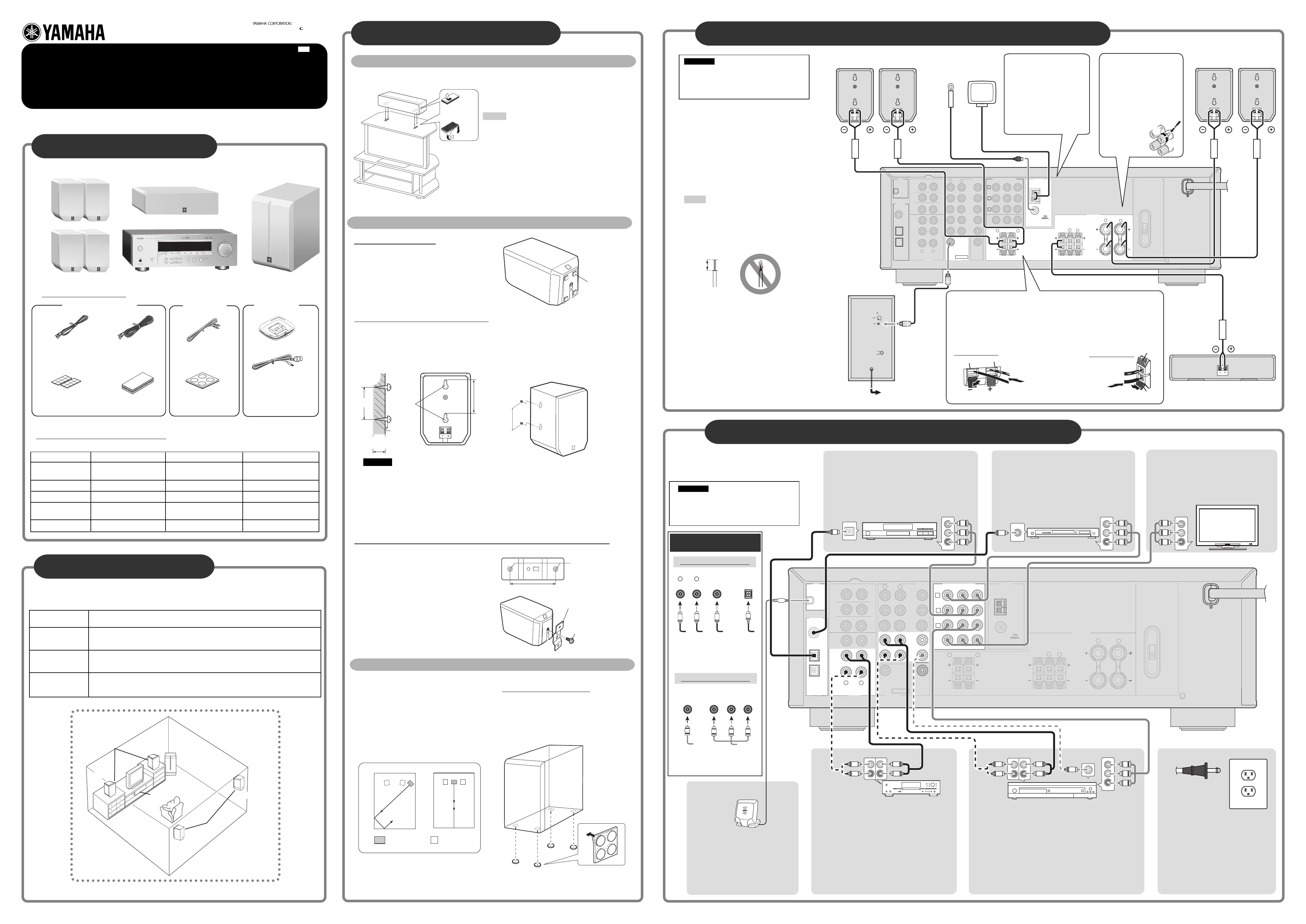
5 Connecting other components to the receiver
red (+)
Note:
Do not insert the
insulation coating into
the hole. The sound may
not be produced.
Connecting to the
receiver terminals of
the Antennas
Locate AM loop antenna and
indoor FM antenna, and connect to
the receiver. For more details, refer
to the “HTR-5930 Owner’s
Manual”.
CAUTION
Plug the power cables for the AV receiver
and other audio/video components into an
AC outlet only after you complete all other
connections.
black (-)
11
11
1 Surround speakers
33
33
3
Front speakers
44
44
4 Subwoofer
55
55
5 Center speaker
Indoor FM antenna
AM loop antenna
red (+)
Speaker terminals
Receiver terminals
HTR-5930
HTR-5930
44
44
4
XM Connect-and-
Play digital antenna
Connect the XM Connect-and-Play digital
antenna accessory (sold separately) to the
XM jack.
To AC outlet
(U.S.A. model only)
This procedure introduces an example of digital and
analog connections. For information about other
connection methods, refer to the “HTR-5930
Owner’s Manual”.
33
33
3
Video monitor
Connect the component video input jacks of video
monitor to the COMPONENT VIDEO (MONITOR
OUT) jacks of this unit using a component video
cable.
11
11
1
Cable TV or satellite tuner
1. Connect the component video output jacks of your cable TV
or satellite tuner to the COMPONENT VIDEO (DTV/CBL)
jacks of this unit using a component video cable.
2. Connect the optical digital audio output jack of your cable
TV or satellite tuner to the DIGITAL INPUT (DTV/CBL)
jack of this unit using an optical digital audio cable.
22
22
2
DVD player
1. Connect the component video output jacks of your DVD
player to the COMPONENT VIDEO (DVD) jacks of this
unit using a component video cable.
2. Connect to the optical digital audio signal output jack of
your DVD player to DIGITAL INPUT (DVD,COAXIAL)
jack using an optical digital audio cable.
VIDEO
COMPONENT VIDEO
Y PB PR
PB
Y
P
R
V
COAXIAL
DIGITAL AUDIO
AUDIO
OPTICAL
DIGITAL AUDIO
R
L
C
O
R
L
Left and right
analog audio
cable plugs
Coaxial digital
audio cable
plug
Optical digital
audio cable
plug
Composite video
cable plug
Component video
cable plug
Connecting to the
receiver terminals of
the front speakers
1 Loosen the knob.
2 Insert the bare wire core of the
speaker cable into the hole on
the terminal.
3 Tighten the knob to secure the
wire.
Right
Left
Right
Left
Digital out (optical)
Video out
(Component)
Video out
(Component)
Video in
(Component)
Audio out
Audio out
Video out (Component)
Subwoofer
cable
77
77
7
Plug in the power
After you complete all cable connections,
plug in the receiver, subwoofer, DVD player
and other components to the AC outlet.
Information on jacks
and cable plugs
Video jacks and cable plugs
Audio jacks and cable plugs
22
22
2 Antennas
Connecting to the speaker or the receiver terminals
1 Press and hold the terminal tab, as shown in the figure below.
2 Insert the bare wire core.
3 Release your finger from the tab to allow it to lock securely on the bare wire core.
4 Test the security of the connection by pulling gently on the cable at the terminal.
CAUTION
Plug the power cables for the AV receiver
and other audio/video components into an
AC outlet only after you complete all other
connections.
Keep the speaker cables as short as
possible. Do not bundle or roll up excess
cable. If the connections are faulty, you will
hear no sound from the speakers.
Before connecting
• Cut the supplied speaker cable to the appropriate
length as required.
• Remove the insulation coating at extremity of each
speaker cable by twisting the coating off.
Notes
• Do not let uninsulated bare wires touch each other as this
could damage the speaker or the amplifier.
• Securely twist the bare wires and lump them together to
prevent them causing a short circuit.
Good
Not Good
10 mm
(3/8”)
4 Connecting speakers and antennas to the receiver
black (-)
(white)
(red)
(yellow)
(orange)
(green)
(red)(blue)
55
55
5
CD recorder or MD
recorder
Connect the analog audio output jacks of your CD recorder
or MD recorder to the MD/CD-R IN (PLAY) jacks on this
unit using an analog audio cable (stereo).
y To record audio sources output at the MD/CD-R OUT
(REC) jacks, you need to connect the source component
using an analog connection. For details, refer to the
“HTR-5930 Owner’s Manual”.
66
66
6
DVD recorder or VCR
1. Connect the component video output jacks of your DVD recorder or
VCR to the COMPONENT VIDEO (VCR) jacks of this unit using a
component video cable.
2. Connect the analog audio output jacks of your DVD recorder or VCR to
the AUDIO VCR IN jacks on this unit using an analog audio cable.
y To record audio and video sources output at the VCR OUT jacks, you
need to connect the source component using an analog connection. For
details, refer to the “HTR-5930 Owner’s Manual”.
Digital out
(coaxial)
AM loop antenna
Indoor FM antenna
Remote control, Batteries (AA,
R06, UM-3) x 2 and Owner’s
manual are also included, but
not shown.
For HTR-5930
UC
Audio in
Audio in
Video in
00_01_EN_YHT-270_UC.pm 12/20/05, 3:25 PM1

