Page is loading ...

OWNER’S REFERENCE
EVOLUTION
EVOLUTION AMPLIFIERS
302 AND 402 STEREO
403 THREE-CHANNEL
600 AND 900 MONAURAL

Evolution 302, 402, 403, 600 and 900 Power Amplifiers
O
wner’s Reference, v07.0
Krell Industries, Inc.
45 Connair Road
Orange, CT 06477-3650 USA
This product complies with the EMC directive (89/336/EEC) and the low-voltage directive
(73/23/EEC).
IMPORTANT SAFETY INSTRUCTIONS
1. Read Instructions.
2. Keep these Instructions.
3. Heed all Warnings.
4. Follow all Instructions.
5. Do not use this apparatus near water.
6. Clean only with a dry cloth.
7. Do not install near any heat sources such as radiators, heat registers, stoves, or other appa-
ratus (including amplifiers) that produce heat.
8. Unplug this apparatus during lightning storms or when unused for long periods of time.
9. Refer all servicing to qualified service personnel. Servicing is required when the apparatus
has been damaged in any way, such as a power-supply cord or plug is damaged, liquid has
been spilled or objects have fallen into the apparatus, the apparatus has been exposed to
rain or moisture, does not operate normally, or has been dropped.
10. An Evolution amplifier must be placed on a firm, level surface where it is not exposed to drip-
ping or splashing.
11. The ventilation grids on the top of every Evolution amplifier, the ventilation grids on the back of
the Evolution 302 amplifier, and the space underneath every Evolution amplifier must be unob-
structed at all times during operation. Do not place flammable material above or beneath an
Evolution amplifier
.
12. Before making connections to an Evolution amplifier, ensure that the power is off and other com-
ponents are in mute or stand-by mode. Make sure all cable terminations are of the highest quali-
ty
, fr
ee fr
om frayed ends, shor
t circuits, or cold solder joints.
13. THERE ARE NO USER SERVICEABLE PARTS INSIDE AN EVOLUTION AMPLIFIER.
Please contact Krell if you have questions not addressed in this guide.
This pr
oduct is manufactured in the United States of America. Krell
®
is a r
egistered trademark of Krell Industries, Inc., and is restricted for use by
Krell Industries, Inc., its subsidiaries, and authorized agents. CAST
™, Evolution CAST™, and Krell Current Mode™ are trademarks of Krell
Industries, Inc. All other trademarks are registered to their respective companies.
© 2007 by Kr
ell Industries, Inc. All rights reserved P/N 309888
TEL 203-298-4000
FAX 203-891-2028
E-MAIL [email protected]
WEBSITE http://www.krellonline.com

3
Contents
List of Illustrations, page 4
A Letter from Dan D’Agostino, page 5
SECTION ONE: Evolution Amplifier Features and Technology, page 6
Featur
es, Revolutionary Krell CAST Technology,
Definition of T
erms
SECTION
TWO: Unpacking and Placement, page 11
Opening the Evolution Amplifier Shipping Carton
SECTION THREE: Anatomy of the Evolution Amplifier, page 13
Front Panel Description, and Back Panel Description
SECTION FOUR: Connecting an Evolution Amplifier to Your System, page 21
CAST Connections, Balanced Connections, Single-ended Connections,
Evolution DC Protection Circuitry/Using Tube Preamplifiers, Connection Steps
SECTION FIVE: Evolution Amplifier Operation, page 23
On/Off and Stand-by Operation
SECTION SIX: Troubleshooting System Noise, page 24
How to Evaluate Amplifier Operation, Error Codes
SECTION SEVEN: Questions and Answers, page 26
W
ARRANTY
, page 27
RETURN AUTHORIZATION PROCEDURE, page 29
SPECIFICATIONS, page 30

4
List of Illustrations
Figure 1, page 13
Evolution Amplifier Front Panel
Figure 2, page 15
Evolution 302 Back Panel
Figure 3, page 16
Evolution 402 Back Panel
Figure 4, page 17
Evolution 403 Back Panel
Figur
e 5, page 18
Evolution Monaural Amplifier Back Panel

5
A Letter from Dan D’Agostino
Dear Audio Enthusiast,
Thank you for your purchase of a Krell Evolution Series amplifier.
Evolution Series amplifiers continue my quest for amplifiers that deliver absolute
truth in music reproduction. These four new models utilize Active Cascode
Topology, a unique circuit technique that minimizes distortion by applying from 2
to 3 times more active devices to each gain stage. Evolution Series amplifiers
bring the real-life dynamics and transparency for which Krell is famous, to a whole
new level.
Krell amplifiers are best known for their ability to drive any loudspeaker to sound
its best, without regard to impedance or efficiency. I believe that linearity, an
amplifier
’s ability to output an exact duplicate of the input signal, is the ultimate
measure of that amplifier’s work. At Krell, I drive amplifier designs toward the com-
mon goal of linearity, through the rigorous application of Krell design principles
that focus our efforts on four major performance factors: distortion, bandwidth,
output impedance, and current capability
. The Evolution Series amplifiers are a
synthesis of these factors.
The Evolution Series amplifiers use Evolution CAST technology
, for superior per
-
for
mance and ver
y low noise.
I hope that you enjoy your new Evolution Series amplifier.
Sincerely,
Daniel D’Agostino
Chief Executive Officer

6
SECTION ONE
Evolution Amplifier Features and Technology
This section describes the innovative features and technology of the Evolution
Series amplifiers, and defines CAST and other key terms used in this reference.
There are five amplifier models in the Evolution Series: the 302 Stereo Power
Amplifier, the 402 Stereo Power Amplifier, the 403 Three-channel Power Amplifier,
the 600 Monaural Power Amplifier, and the 900 Monaural Power Amplifier.
Features
Evolution Series amplifiers are designed with a signal path that incorporates Krell
Current Mode and CAST circuitry.
All amplifiers feature massive power supplies. The power supply makes use of
extensive electrical and magnetic shielding to keep radiated interference out of
critical amplifier circuits.
The Evolution 302 design utilizes a 3000 VA power supply. The Evolution 402 and
Evolution 600 are equipped with a 5000 VA power supply, and the Evolution 403
and Evolution 900 house 6000 VA power supplies.
Inter
nal high-current line conditioning circuitry filters RF noise on the AC mains, as
well as compensating for asymmetrical power waveforms and DC on the mains.
Advanced microprocessor control monitors critical operational parameters. Output
current, DC offset, rail voltages, and operating temperature are all continuously
monitored.

7
Revolutionary Krell CAST Technology
Current Audio Signal Transmission, termed CAST, is a revolutionary method of
connecting analog audio components for unparalleled sonic performance.
Innovative engineering combines the new Krell CAST circuitry with existing Krell
Current Mode technology to create entire CAST systems that reproduce music
with incredible range, tonality, and precision.
The Voltage Signal Transmission
and the Traditional Audio System
Traditionally, signal is transmitted in the voltage domain between two components.
In an audio system, each component is a discrete entity with unique characteris-
tics that act upon the musical signal independently. Each component is unaware
of the other components in the system. The cables that connect the components
also have their own electrical characteristics, which affect the sonic presentation
of the entire system. CAST transmission unifies individual components and inter-
connects into an electrically-linked whole. The original signal remains unaltered
from sour
ce to speaker.
CAST Basics
Here is how a CAST audio system works. Internally, each CAST source transfers,
or amplifies, current using Krell Current Mode circuitry. This current signal is then
output using CAST circuitry. When the signal is received by a CAST input, Krell
Cur
r
ent Mode cir
cuitr
y again takes over until the signal r
eaches the loudspeaker.
By maintaining the musical signal in the cur
r
ent domain fr
om beginning to end, an
entire CAST system behaves as if it is one component. With CAST, circuit board
pr
oper
ties and signal transmission aber
rations between components ar
e eliminat
-
ed. Cable impedances and their ef
fects on the transmitted signal ar
e non-existent.
How CAST and Krell Current Mode Interact
While CAST is a new method of transferring the musical signal between compo-
nents, its origin stems from Krell Current Mode, the technology developed to
transfer the musical signal within a component. CAST combined with Krell Current
Mode circuitry takes signal transmission to the next evolutionary level. In essence,
continue
d

8
Krell Current Mode maintains the integrity of the signal within the component and
CAST preserves the transmitted signal between components. Together, CAST and
Krell Current Mode technologies unify separate Krell components into a
single
global circuit.
Krell Current Mode technology enjoys bandwidth increases up to an
order of magnitude greater than their voltage based counterparts. This dramatic
increase in circuit bandwidth delivers near perfection in the audible band that typi-
cally suffers from phase distortions in voltage circuits.
CAST Cable Construction
A CAST system uses cables manufactured by Krell and other manufacturers spe-
cially licensed by Krell. Thin and flexible CAST cables ar
e constructed with the
same build quality as other Krell components and are aesthetically matched to the
components that Krell manufactures. An all-metal body and locking connectors
with gold contacts ar
e part of the standard no-compromise specification devel-
oped for every CAST cable made.
Evolution CAST
By employing revolutionary current mirror circuitry, the Evolution amplifier compo-
nents raises CAST technology to another level. This advanced use of the technol-
ogy increases the linearity, transient speed, and bandwidth of the Evolution com-
ponents while reducing the distor
tion by an order of magnitude.
The Best Musical Performance
When you operate a CAST system, you will hear significant impr
ovements in every
per
for
mance ar
ea: speed, pr
ecision, dynamic range, depth and width of the sound
stage, transient impact, tonal balance, har
monic distor
tion, and mor
e. The goal for
CAST is the same company goal used for all Krell products. Krell strives for the
deliver
y of the best per
for
mance of a musical event for you, using the full expr
es
-
sion of technology to date.
(SECTION ONE: Evolution Amplifier Features and Technology continued)

9
Definition of Terms
The following are definitions of key terms used in this owner’s reference:
Inputs and Outputs
Balanced
A symmetrical input or output circuit that has equal impedance from both input
terminals to a common ground reference point. The industry standard for profes-
sional and sound r
ecording installations, balanced connections have 6 dB more
gain than single-ended connections and allow the use of long interconnect cables.
Balanced connections ar
e completely immune to induced noise from the system
or the environment.
CAST and Evolution CAST
Krell Current Audio Signal Transmission, or CAST, is a proprietary Krell circuit tech-
nology for connecting analog components, transmitting the audio waveform
between components in the current domain rather than in the voltage domain. The
speed and bandwidth pr
ovided by Krell CAST and its circuitry update, Evolution
CAST, yield accurate, realistic music r
eproduction, enabling connected compo-
nents to perform as if they are all part of a single circuit. CAST and Evolution CAST
are balanced connections, and reject induced noise.
Single-ended
A two-wire input or output circuit. Single-ended connections are not recommend-
ed for connections requiring long cable runs. Use care when using single-ended
connections, because the ground connection is made last and broken first. Turn
the system off/on prior to making or breaking single-ended connections.
Operation
Off
When the power status indicator is not illuminated, the amplifier is of
f.
Stand-by
A low-power-consumption status that keeps the audio and power supply circuits
at idle. The power status indicator is illuminated in red, when the amplifier is in
stand-by mode. Krell recommends leaving the amplifier in stand-by mode when it
is not playing music.
Operation
When the power button is pressed, and the power status indicator is illuminated in
blue, the amplifier is in operational mode and ready to play music.
continue
d

10
Technology
Active Cascode Topology
A unique circuit technique that minimizes distortion by applying from 2 to 3 times
more active devices to each gain stage thereby reducing the load on individual
devices and improving circuit-wide linearity.
Krell Current Mode
A proprietary Krell circuit topology in which the audio gain stages of a component
operate in the current domain rather than the voltage domain. This unique technol-
ogy provides the component with exceptional speed, and a wide bandwidth.
(SECTION ONE: Definition of Terms continued)

11
Unpacking and Placement
This section describes the procedures for safely unpacking and placing your
Evolution amplifier. The amplifier and accessories are shipped in 1 carton. The
dimensions of the amplifier are shown in the specifications section starting on
page 30.
T
wo people are needed to remove the Evolution amplifier from its shipping box
safely and easily.
Opening the Evolution Amplifier Shipping Carton
1. Open the shipping carton and remove the top layer of foam. The carton con-
tains these items:
1 Evolution amplifier chassis
1 20 amp AC power cord
1 12 VDC (12 V trigger) cable
1 Packet containing the Quick Setup Guide and the warranty registration card
2. Orient the shipping box so that one person stands at the front of the amplifier
and one person stands at the back of the amplifier. Both people need to grab
a pair of the cardboard handle cutouts (one pair located at the front of the
amplifier and one pair located at the back of the amplifier) and simultaneously
lift the amplifier straight up, out of the car
ton. Bend and lift with your knees,
not your back.
3. Place the amplifier in a safe location, and remove the protective plastic wrap-
ping.
N
ote
Save all packing materials. If you need to ship the Evolution amplifier in future, repack
the unit in its original packaging to prevent shipping damage.
SECTIONTWO
continue
d

12
Placement
Before you install an Evolution amplifier into your system, please follow the guide-
lines in this section to select a location for your component. This will facilitate a
clean, trouble-free installation.
Place the amplifier on a firm, level surface, away from excessive heat, humidity, or
moisture. Each Evolution amplifier requires at least two inches (5 cm) of clearance
on each side and at least eight inches (20 cm) of clearance above the component
to provide adequate ventilation.
If you place the amplifier in a closed cabinet, you may need to modify shelf spac-
ing or use small fans to increase ventilation. When the front and back of a cabinet
are open, the air space between the chassis and shelf must be unobstructed.
Place the amplifier(s) as close to the loudspeakers as possible. While Evolution
CAST technology permits long interconnect cable lengths, keep loudspeaker
cable lengths to a minimum.
AC Power Guidelines
The Evolution amplifier requires a dedicated AC circuit rated at a minimum of 20
amps. Do not use extension cords, multiple AC adapters, or AC power strips.
Note
Do not operate the Evolution amplifiers with any device designed to alter or condition
AC power.
(SECTION TWO: Unpacking and Placement continued)

13
SECTION THREE
Anatomy of an Evolution Amplifier
This section describes Evolution amplifier functions.
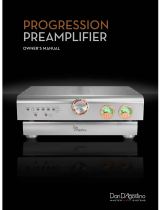
Figure 1 Evolution Amplifier Front Panel (Evolution 402 shown)
1 Power Button
2 Power Status Indicator
Power
continue
d

14
Front Panel Description
See Figure 1 on the previous page
Evolution amplifier front panel functions are described below:
Power
1 Power Button
Press this button to place the Evolution amplifier in operational mode.
2 Power Status Indicator
The power status indicator is illuminated in red when the amplifier is in stand-
by mode. The indicator illuminates in blue when the amplifier is in operational
mode. If there is no illumination, please check the following items:
—The power cord is connected to the amplifier
—The power cord is plugged into a live AC power supply
—The back panel power breaker switch (10) is set to the on position
—The back panel backlight switch (8) is set to the on/ext position.
(
SECTION THREE: Anatomy of an Evolution Amplifier continued)

15
Figure 2 Evolution 302 Stereo Amplifier Back Panel
3 Loudspeaker Binding Posts
4 CAST Inputs
5 Single-ended Inputs
6 Balanced Inputs
7
12 VDC Out/In (12 V Trigger)
8 Backlight Control
9
IEC Power Cord Receptacle
10
Power Breaker Switch
Inputs
Outputs
Remote
Power
continue
d

16
Figure 3 Evolution 402 Stereo Amplifier Back Panel
3 Loudspeaker Binding Posts
4 CAST Inputs
5 Single-ended Inputs
6 Balanced Inputs
7
12 VDC Out/In (12 V Trigger)
8 Backlight Control
9
IEC Power Cord Receptacle
10
Power Breaker Switch
Inputs
Outputs
Remote
Power

17
Figure 4 Evolution 403 Multi-channel Amplifier Back Panel
3 Loudspeaker Binding Posts
4 CAST Inputs
5 Single-ended Inputs
6 Balanced Inputs
7 12 VDC Out/In (12 V Trigger)
8 Backlight Control
9 IEC Power Cord Receptacle
10
Power Br
eaker Switch
Inputs
Outputs
Remote
Power
(
SECTION THREE: Anatomy of an Evolution Amplifier continued)
continue
d

18
Figure 5 Evolution Monaural Amplifier Back Panel (Evolution 600 shown)
3 Loudspeaker Binding Posts
4 CAST Input
5 Single-ended Input
6 Balanced Input
7 12 VDC Out/In (12 V Trigger)
8 Backlight Control
9 IEC Power Cord Receptacle
10 Power Br
eaker Switch
Inputs
Outputs
Remote
Power

19
Back Panel Description
See Figure 2, 3, and 4 on the previous pages
The amplifier back panel provides access to the input and output connections,
12 V trigger inputs and outputs, and the AC power connection and switch. Back
panel features and their descriptions follow:
Outputs
3 Loudspeaker Binding Posts (one pair per channel)
Each channel has one positive and one negative binding post. They accept
spade lugs only.
Inputs
4 CAST Inputs (one per channel)
These are CAST inputs with 4-pin bayonet connectors, for use with Krell
CAST-equipped preamplifiers and components.
5 Single-ended Inputs (one per channel)
These are single-ended analog inputs with RCA connectors.
6 Balanced Inputs (one per channel)
These ar
e balanced analog inputs with XLR connectors.
(
SECTION THREE: Anatomy of an Evolution Amplifier continued)
continue
d

20
Remote Connections
7 12 VDC In/Out (12 V Trigger)
The 12 V trigger allows you to turn the Evolution amplifier on or off, or to and
from stand-by, from other components.
Out. The output sends 12 VDC (12 V trigger) power on/off signals to other Krell
components and other devices that incorporate a 12 V trigger, allowing whole
systems or parts of systems to be easily controlled remotely. Mono 3.5 mm
connectors are used in the following configuration: Tip = +12 V, Sleeve = GND.
Notes
When an Evolution amplifier is in the operational mode, the 12 V trigger provides 12 Volts
of DC output. When the amplifier is in the stand-by mode or off, the DC output is
0 Volts. A maximum of 30 mA is available from the 12 V trigger output.
Consult the owner's reference of the components used in a custom installation to take
full advantage of the remote capabilities of an Evolution amplifier.
8 Backlight Control
Ext In.
Connect a 12 V trigger to the Ext In input connector to turn off the
power status indicator (2) using a remote control. The switch must be set to
On/Ext, in order for this to function (see below).
On/Ext. This activates the power status indicator. (This is the factory default
position.)
Off. This turns off the power status indicator, during normal operation. The
power status indicator remains illuminated for ten seconds after the power but-
ton is pr
essed.
Power
9 IEC Power Cord Receptacle
The power r
eceptacle is for use with the pr
ovided 20 amp AC power cor
d. Use
only the power cord supplied with your Evolution amplifier.
10
Power Br
eaker Switch
Place this switch in the up position to put the amplifier in stand-by mode.
Place the switch in the down position to turn off the amplifier.
/