Page is loading ...

1
Manufactured by:
HELLENBRAND, INC.
404 Moravian Valley Road • Waunakee, Wisconsin 53597
www.hellenbrand.com • [email protected]
Owner’s Manual
ProMate-6 / Iron Curtain
®
2.0 Demand Aeration Manual
U.S. Patent No. 7,156,995 B2, 7,491,321 & 7,638,063
108038
Updated 11/19/15-LBRY
©2009-2015

2
INSTALLATION DATA
Date of Installation __________________________________________________
Filter Model Number _________________________________________________
Aeration Model Number ______________________________________________
Address of Installation ________________________________________________
Installed By _________________________________________________________
Raw Water Test: Iron_______ Manganese_______ pH_______ Hydrogen Sulde_______
TDS_______ Iron Bacteria_______ yes _______ no Tannins_______
Hardness ______ Alkalinity _______
Automatic Filter Regeneration: Every _______ Days
Frequency of Air Recharge: Every _______ Gallons
Continuous Water Supply Flow Rate @ 30 PSI (While the pump is running) _______ Gallons Per Minute (gpm)
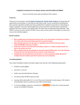
Congratulations on your purchase of one of the nest water treatment systems available today – the Iron
Curtain
®
System. This patented, non-chemical lter system, will remove iron, manganese and/or hydrogen sulde from your
water supply when properly applied.
This owner’s manual is designed to assist owners and installers with the operation, maintenance, and installation of your new
iron removal system. It is our sincere hope that this manual is clear, concise, and helpful to both owner and installer. We have
included detailed instructions of general operating conditions, pre-installation, installation, start-up, and timer settings.
Questions? Should you have any questions regarding the installation, operation or servicing of this system, please
contact the dealer you purchased this system from. Your dealer will be familiar with your particular situation, your water
conditions, etc. and should be able to address your concerns promptly and eciently.
TABLE OF CONTENTS
Installation Data ........................................................................................................................................................................... 2
Iron Curtain
®
2.0 Principle of Operation, Operation of Aeration System..................................................................................... 3
Operating Conditions .................................................................................................................................................................. 4
Pre-Installation Check List .......................................................................................................................................................... 4
Installation Instructions & Start-Up ............................................................................................................................................. 5
Specications .............................................................................................................................................................................. 6
Backwash Frequency, Air Recharge Frequency .......................................................................................................................... 6
Installation Diagram ..................................................................................................................................................................... 7
Iron Curtain
®
2.0 Assembly ......................................................................................................................................................... 8
Programming ..........................................................................................................................................................................9-13
Iron Curtain
®
System Diagram .................................................................................................................................................. 14
Iron Curtain
®
Wiring ................................................................................................................................................................... 15
Bypass Valve Operation ............................................................................................................................................................ 16
Iron Curtain
®
Flow Diagrams ................................................................................................................................................17-18
Troubleshooting .................................................................................................................................................................... 19-21
In/Out Options ......................................................................................................................................................................21-22
Compressor Service Kit........................................................................................................................................................23-25
Chemical Feed Wiring Diagrams ..........................................................................................................................................26-27
Iron Curtain
®
2.0 Limited Warranty ............................................................................................................................................ 28

3
IRON CURTAIN
®
2.0
The advantages of a multi-media bed are:
1. Longer runs between backwash times.
2. Caking of the bed and breakthrough turbidity are virtually
eliminated.
3. Much higher service ow rates per square foot.
4. Higher degree of clarity because of the heavier, ner lter
media in the bottom.
The standard Iron Curtain
®
System uses four layers of lter
media. The top layer is made up of large, lighter weight par-
ticles. The second layer contains a slightly heavier media.
The third layer contains a much heavier media, smaller in
size than the one above. The fourth layer is a special sup-
port bed to retain lter media so it does not pass through
the distribution system, and allows an even distributed ow
of backwash water.
Operation of Aeration System
The Iron Curtain
®
System introduces air into the aeration
tank and bleeds o the old head of air automatically. A relay
controls the air recharge cycle and how frequently it occurs.
The relay turns on the air pump, opening the drain port and
the top air recharge port of the aeration tank. The air pump
runs for a pre-set amount of time, replenishing the head of
air and discharging excess water and/or air to drain.
Advantages Over
Other Systems
1.
The original system was tested and validated by WQA.
2. Uses no chemicals or salt.
3. Eliminates the need for air injectors, venturis, or micron-
izers that can plug with iron.
4. No oats or air volume controls are used to regulate air
volume in aeration tank which “foul” from iron.
5. Two-tank system consisting of a pressurized aeration
tank and multi-media depth lter.
6. 110V aeration pump to recharge aeration tank.
7. "Piggy-back" plug allows control valve to be plugged
into same outlet.
8.
Can be used on shared wells, municipal water supplies, or
with buried pressure tanks without additional equipment.
9. Higher service ow rates.
10. Better ltration results.
11. U.S. Patents #B1 5,096,596 and 7,156,995.
12. Variable settings on air recharge that is independent of
backwash frequency.
13. Can reduce both dissolved and particulate iron.
Iron Filtration System
Aeration/precipitation/multi-media ltration for:
1. Iron Reduction/Removal
2. Manganese Reduction/Removal
3. Hydrogen Sulde Reduction/Removal
Principle of Operation
The Iron Curtain
®
System uses a three step process of
oxidation, precipitation, and mechanical ltration for
the reduction/removal of iron, manganese, and hydrogen
sulde. The process of how the Iron Curtain
®
System does
each one of these separate procedures is the key to the
successful results this product has obtained in the market
place. There are two main components that make up the
Iron Curtain
®
System. They are:
1. Iron Curtain
®
2.0 Aeration Assembly
2. Iron Curtain
®
Multi-Media Depth Filter
1
The rst step in any oxidizing process is to bring the
raw water into intimate contact with a strong oxi-
dant. This will begin to convert the dissolved element such
as iron or manganese to a physical particle or nonsoluble
precipitate. A strong, inexpensive, environmentally-safe oxi-
dant is oxygen, which makes up about 21% of ambient air.
To do this, the Iron Curtain
®
System sprays water through
a regulated head of air in the aeration tank.
2
The second step in this three step process is to
provide adequate reaction or contact time for the
precipitation reaction to go to completion. This allows
time for the iron and/or manganese particles to become large
enough to lter out. The aeration tank with the Iron Curtain
®
System allows for several minutes of contact time at the rated
service ows, compared to only seconds on other systems.
It should be noted that this reaction time will also be aected
by temperature; the warmer the water the faster the reac-
tion. A low pH can slow the oxidation reaction of the iron.
This reaction time may also be aected by the presence of
organic material (such as tannins). If tannins are present,
eld tests have shown that they will not be removed and
will also hinder the ability of this system to eectively
remove iron, manganese, and/or hydrogen sulde. Instal-
lation of this system on water supplies with more than
0.5 ppm of tannins will void warranty.
3
The third and nal step is ltration for the removal of
the precipitates from the water. A WQA Water Filtration
Study Guide states:
“The ideal lter bed would be one with large grains at the top
to prevent the formation of a surface cake and to provide
large pores for course particles and small grains at the bot-
tom to entrap smaller particles. This allows the entire depth
of the bed to be used as a lter. This also allows for longer
lter runs and faster ow rates. Unfortunately, such an ideal
bed, when consisting of a single media is not possible, the
way to solve this problem is to use layers of media.”

4
Operating Conditions
The original Iron Curtain
®
System has been validated by the WQA
under their S-200 Filter Standard for the reduction/removal of
iron, manganese, and/or hydrogen sulde. The concentration
limits listed below reect the maximum individual limit that each
contaminant was tested for separately without any interference
of other contaminants in the inuent water.
In reality, these contaminants may be present in combination
which may limit the lter’s ability to remove these contaminants
in higher concentrations. In some cases, individual sellers of this
equipment have had success removing higher concentrations
of contaminants—iron, for example—above the limitations we
have listed. If you are considering the installation of this system
for the reduction/removal of iron, manganese and/or hydrogen
sulde levels that are above operating conditions listed below,
we recommend that you consult your dealer for proper applica-
tion. Installation of this system under these circumstances may
void part(s) and/or all of the system warranty.
pH — The pH level of the inuent water must be 7.0 or higher
for iron oxidation reaction to proceed per the engineering speci-
cations.*
Iron — This system is rated for a maximum of 10 ppm of ferrous
(clear water) and/or ferric (red water) iron.*
Iron Bacteria — If iron bacteria are present; more frequent service
may result, life of the Iron Curtain
®
system may be limited and
the system may be unable to properly remove iron. By properly
controlling the iron bacteria with chlorine or other approved
methods for bacterial reduction, the Iron Curtain
®
System will
function properly. One option to control iron bacteria within
the Iron Curtain
®
is chlorine injection during the regeneration
cycle. In some instances, continuous chlorination of the
water supply may be needed.
Hydrogen Sulde — Sometimes referred to as "rotten egg" odor.
This system is rated for a maximum of 10 ppm hydrogen sulde.
Hydrogen sulde levels vary depending on barometric pressure.*
Manganese — Limit 2.0 ppm; amounts present over 2.0 ppm may
gradually prevent iron removal. Note: For optimum manganese
reduction, pH should be greater than 8.5.*
Organic Matter (Tannins) – The presence of organic matter such
as tannins will prevent the oxidation process of converting the
dissolved element, such as iron or manganese, to a nonsoluble
precipitate or solid substance. In other words, organics can tie
up the iron preventing ltration. The presence of organics such
as tannins above 0.5 ppm voids any claims for this system to
perform as stated above. In some applications, tannin levels
below 0.5 ppm or the presence of other organics may hinder
the operation of this system.*
Chlorine — The presence of chlorine in the raw water supply
ahead of this system should be limited to a maximum of 1.0 ppm
residual and 0.5 ppm or less when fed continuously.
Total Dissolved Solids (TDS) — While TDS does not directly
aect iron removal, it is a good indicator of potential interference.
Most waters have TDS less than 500 and generally present no
problems to iron reduction. If any ion becomes excessive, it may
cause failure of iron removal. A TDS more than 750 ppm voids
any claims for this system to perform as stated above.*
Pre-Installation Check List
Water Pressure: A minimum of 30 psi at a predetermined con-
tinuous ow rate is required to backwash the lter properly, with
a maximum of 70 psi to be used.*
Actual Inuent Flow Rate: (Water available from well pump,
service inlet, etc.) The actual ow rate must exceed the backwash
rate for the model of lter selected at a minimum of 30 psi for
the entire length of the backwash cycle. See actual backwash
rates in the Specications section on page 6.
Electrical Requirements for Filter Control: A continuous 110
volts is required to cycle the controls and aeration pump. Make
certain the electrical supply is always on and cannot be turned
o with another switch.
Existing Plumbing: The condition of the existing plumbing should
be free from lime and iron build-up. Piping that is heavily built-up
with lime and/or iron should be replaced.
Equipment Location: See Figure 1,on page 7.
Location of Aeration and Filter Tank: See Figure 1 on page 7.
These two tanks should be installed after the pressure tank and
as close to each other as practical. If you want to lter outside
hosebibs, be sure the lter system is properly sized to handle
the ow rates required for extended periods of time, in addition
to the normal household demand.
Drain Lines: All lter system drain lines must be a minimum of
3/4" or equal to the size of the drain line connection at the control
valve or larger. Avoid overhead drain lines when possible. If used,
overhead drain lines are not to exceed a height of ve feet above
the control valve and should be no more than fty feet in length.
Check Valve: On applications where there is a non-ltered
demand for water such as joint wells (where the lter system is
only installed in one of two or more homes), outside hosebibs,
farms with outbuildings, yard hydrants, etc. a spring loaded check
valve is provided and must be installed ahead of the aeration
tank. See Figure 1, on page 7. Install the check valve in a vertical
upow position with a minimum 6" water column above the check
valve. This prevents air from escaping past the check valve. If
the check valve is installed in a horizontal position, and there is
a simultaneous demand for both non-ltered and ltered water,
the air head in the aeration tank may escape backwards past
the check valve into the non-ltered water line.
By-Pass Valves: Always provide for a bypass on the lter system.
It is recommended that a bypass be placed on both the aeration
tank and the lter tank.
Filtered Water: Normally, ltered water is furnished to all house-
hold lines; however, outside faucets are typically left on raw water.
If ltered water is provided to outside faucets, the lter system
must be sized accordingly.
Caution: Iron Curtain System controls and/or air pumps are
NOT designed to be installed outdoors with direct exposure
to the elements. Hellenbrand recommends lter systems to
be installed indoors or under a protective shelter protected
from the elements. Contact your Hellenbrand representative
to inquire about rainproof covers. The water pressure is not
to exceed 70 p.s.i.; water temperature is not to exceed 110°
F; lter system cannot be subject to freezing conditions; lter
system cannot be subject to a negative pressure or vacuum. On
installations where there is the possibility of a negative pressure
or vacuum, a vacuum breaker or check valve must be installed
at the inlet of the conditioner. For example, if the water service is
interrupted due to a water pipe break, well pump being serviced,
etc., a back siphon could occur causing a vacuum or negative
pressure on the ltration equipment.
*For application parameters outside the specied operation
conditions or additional information regarding the listed
items, contact your dealer.

5
Installation Instructions
Your new Iron Curtain
®
model IC-2.0 allows for simple installa-
tion and start up. Installation diagrams are provided to assist
you. Use of these diagrams and the following procedures
will ensure that the system is properly installed.
1. Follow all state and local plumbing and electrical
codes!
2. The inlet check valve must be installed in the upow posi
-
tion on the raw water supply feeding the aeration tank.
(See gure 1 page 7 for proper check valve installation
procedures)
3. When installing an Iron Curtain
®
Filter system it is com-
mon to provide ltered water to some xtures such as
the kitchen cold faucet. This is typically done as a matter
of personal preference. In rare occasions it has been
noted that the customer may experience some air in
the ltered water line on the morning after regeneration.
It
has proven to be benecial to plumb the line for the
ltered-only water xture in a downward direction before
the inlet to the softener (12 inches recommended), then
make a reverse turn and go upward toward the xture.
Understanding that air always rises to the highest point
in a water system, and it cannot naturally ow downward.
(Figure 1, page 7)
4. The raw water supply from the outlet of the check valve
must be connected to the down-ow inlet connection on
the aeration tank. Refer to the stickers marked inlet/
outlet for proper connections. A factory by-pass valve
is available and should be installed on the aeration tank
assembly. Leave the aeration tank on by-pass at this
time.
5. The outlet from the aeration tank is then connected to the
inlet of the lter tank. A factory by-pass valve is available
and should be installed on the lter tank assembly.
6. Connect the outlet of the lter system to the water system
lines you are ltering.
7. The IC-2.0 aeration head assembly has a 3/8” drain con
-
nection that must be run to a drain. This can tee into the
drain line of the lter or to a drain independent of the lter
drain. Drain line emits surges of excess air from aeration
tank and must be secured. Tubing has been supplied.
8. There is a 1/4” tube size vent port o of the solenoid valve
which is vented to the atmosphere. This will normally
expel very little moisture unless an internal seal fails within
the valve body. This vent should be run to a drain to
prevent any water damage to the surrounding area,
should the solenoid fail. This must drain downward
to an open atmospheric drain separate from the lter
drain.
9. Recommend 1” diameter pipe between aeration tank
and lter tank.
Wire aeration cable to ProMate6 control, (black wire to RLY
1 and red wire to COM+, install jumper wire between RLY 1
& RLY 2). Plug power connection to PC board and plug unit
into 120V outlet, unit will cycle to service mode.
Must install bypass on each tank
Do not backwash in rst 24 hours
Complete all plumbing connections; inlet, outlet, drain line
and connect 3/8” line at back of aeration assembly and run
to drain (ok to connect to lter drain line).
1. Verify both tanks are bypassed.
2. Flush cold water piping to nearest faucet until air
gone and water is clear.
3. Slowly open inlet valve on AERATION TANK
ONLY to fully open position, slowly open aeration
tank outlet.
4. Leave lter in bypass.
READ COMPLETELY PRIOR TO STARTING SYSTEM
For start-up instructions with chemical feed, see pages 27 and 28
Demand Aeration Iron Curtain
®
2.0 Start-up Instructions
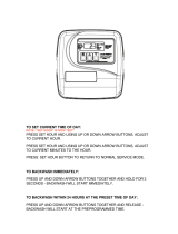
5. Push & hold REGEN button; this will initiate
an air recharge cycle, lter automatically advances
to Backwash when air recharge complete, push
REGEN button to advance to Rinse position.
6. Slowly open lter inlet, unplug power from board.
7. Rinse until clear and close inlet to lter; wait
until water stops running to drain.
8. Plug power back into PC board, unit will cycle to
service.
9. Open lter inlet and outlet.
10. Push SET CLOCK button and use UP/DOWN
arrows to set time of day.
For application specic gallon setting, see page 6 of manual.
Failure to follow proper start-up may result in
equipment malfunction not covered by warranty.
DO NOT OPEN FILTER BYPASS UNTIL INSTRUCTED TO DO SO!

6
Aeration Control Center
Your new IC-2.0 Aeration Control is factory pre-set to cycle
the air compressor every 500 gallons or approximately once
every 24 hours and during lter regeneration. If chem feed
option is used, only one means of initiating air recharge will be
available, see page 26-27 for wiring and programming. The
air pump will begin to run and will automatically shut o and
not aect the functioning of the Iron Curtain
®
.
Iron Curtain
®
Filter Control
Your Iron Curtain
®
Filter is factory preset to backwash every third
day. Adjust as necessary but never backwash less often than
every three days. See lter control owners manual for details.
Regeneration Frequency
Your Iron Curtain
®
Filter System contains a special lter media
mixture which allows it to lter iron longer than standard lters
between backwash regenerations. However, it is our recom-
mendation to leave factory settings as is, unless you wish to
backwash more frequently. You will have to backwash more
frequently if you have higher amounts of iron, iron bacteria,
hydrogen sulde, and/or manganese present in your water
supply. You will also have to regenerate more frequently if
you notice iron bleed through before the end of the normal
service run.
For manual air recharge, push REGEN button until display
changes, this will occur in ltering mode.
Backwash Frequency
0.3 - 3.0 ppm Iron - Every 3rd Day
3.0 - 6.0 ppm Iron - Every Other Day
6.0 - 10.0 ppm Iron - Every Day
10+ ppm Iron - Consult Factory
Specications
Air Recharge Frequency
Recommended duration of pump run time is 10 minutes, and is
factory set to that duration. (Settings Based on Average Pres
-
sure (50psi) and <500 Gallons Daily Use).
Iron Applications
0.3 - 3.0 ppm Iron - Every 500 Gallons
3.0 - 6.0 ppm Iron - Every 500 Gallons
6.0 - 10.0 ppm Iron - Every 250 Gallons
10+ ppm Iron - Consult Factory
Hydrogen Sulde Applications
Hydrogen Sulde (H2S) consumes 7 times the amount of
oxygen to oxidize than iron does. Therefore, for Hydrogen
Sulde Applications, we use the following guideline;
0 - 4 ppm H2S -Every 250 Gallons
4 - 8 ppm H2S - Every 200 Gallons
8 - 10 ppm H2S - Every 100 Gallons
IC-10
PM6.0-IC2.0 10"x54" 1.5 1" 5.0 5.0 26"x68"x16"
IC-10A
PM6.0-IC10A-2.0 10"x54" 1.5 1" 5.0 5.0 26"x68"x16"
IC-10+
PM6.0-IC10A-2.0 10"x54" 1.5 1" 5.0 5.0 26"x68"x16
IC-12
PM6.0-IC12A-2.0 12"x52" 2.0 1" 7.0 8.0 30"x66"x18"
IC-12A
PM6.0-IC12A-2.0 12"x52" 2.0 1" 7.0 8.0 30"x66"x18"
IC-12+
PM6.0-IC12A-2.0 12"x52" 2.0 1" 7.0 8.0 30"x66"X18"
IC-13
PM6.0-IC13A-2.0 13"x54" 3.0 1" 8.0 10.0 32"x68"x20"
IC-13A
PM6.0-IC13A-2.0 13"x54" 3.0 1" 8.0 10.0 32"x68"x20"
IC-13+
PM6.0-IC13A-2.0 13"x54" 3.0 1" 8.0 10.0 32"x68"x20"
Models
Filter &
Aeration
Tank
Size
Floor
Space
(WxHxD)
(2)
Backwash
Rate
GPM
Max.
Service
Flow
GPM
(1)
Inlet/
Outlet
Media
Cu. Ft
(1) Aeration Head and Check Valve have 1” Inlet/Outlet.
(2) Water temps above 60° F will require a higher backwash rate. Consult factory.
Demand Aeration – Factory Settings
Valve Type 1.0 or 1.25 or 1.5 or 2.0
Meter Size 1.5 or 2.0 or 2.0 valves only
Alternator Options OFF
Aux Valve Options OFF
Auxiliary Input OFF
Cycle 1 FILTERING
Cycle 2 BACKWASH
Cycle 3 RINSE
Cycle 4 END
ALT Fill Trigger OFF
Set TYPE Filtering
Cycle 1 Filtering - 10
Cycle 2 Backwash - 12 Min
Cycle 3 Rinse - 6 Min
Gallons Capacity OFF
Set Regen Delayed
Relay 1 Time/Gal/Regen GALLONS
Relay 1 Setpoint 500 Gallons
Relay 1 Duration 10:00 Min
Relay 2 Time/Gal/Regen TIME
Relay 2 Setpoint 0 Min
Relay 2 Duration 10:00 Min
Service Alarm OFF
Scheduled Service OFF
Press NEXT and DOWN arrows together until display changes.
Release and press NEXT and DOWN arrows together until valve
type displayed
Iron Applications
Back to Scrolling Display
Press NEXT and DOWN together until display changes:
Use NEXT button to advance through the screens:

7
Installation Diagram
When installing an Iron Curtain
®
Filter system it is common to provide ltered only water to some xtures such as the kitchen cold
faucet. This is typically done as a matter of personal preference. On rare occasions, the customer may experience some air in the
ltered water line the morning after regeneration. It has proven benecial to plumb the line for the ltered only water xture in a
downward direction from the inlet of the softener (12 inches recommended), then make a reverse turn and go upward toward the
xture. Any accumulated air always rises to the highest point in a water system and cannot naturally ow downward.
Figure 1
Iron Curtain
®
2.0 users will now have two options for the 1’’ inlet check valve. A new in-line check valve is now available in a
plastic vertical elbow connection. The new in-line check valve can shorten installation time and ease future cleaning. Contained in a
vertical adaptor which maintains the protective water column, the quick-connect ttings eliminate two pipe connections, thus short-
ening installation or service time. The original brass check valve, as an individual item, part number: 102792 is always available.
When ordering, please specify which check valve is preferred.
Description Description
Plastic Check Valve Assy Brass Check Valve
Used only on 10-14" diameter
aertation tanks.
Part Number Part Number
104174 102792
(when ordered with IC) (when ordered with IC)
Inlet Check Valve

8
1 ...........110269 .................... Hellenbrand Pump ........................... 1
2 ...........101631 .................... IC Pump Feet ...................................3
3 ...........102137 .................... IC Pump Feet Nut ............................3
4 ...........110470 .................... Elbow, IC Pump 1/4” NPT x 1/4”
Tubing ..............................................1
6 ...........102666 .................... 1/4” Polypropylene Tubing ..............1
(9” required)
7 ...........108010 .................... Relay ................................................ 1
8 ...........108011 .................... Relay Base ....................................... 1
9 ...........102433 .................... Conduit Seal ....................................1
10 ...........101318 .................... Electrical Bushing, 1/2” ...................1
11 ...........103073 .................... Power Cord, 8 ft. .............................1
12 ...........103108 .................... Strain Relief, Elec. Cords ................. 2
13 ...........101547 .................... Upper Distributor Basket ................. 1
14 ...........102479 .................... Screw, Upper Distributor Basket
6-32 x 3/4” 8-18SS .......................... 1
15 ...........102133 .................... Nut, Upper Distributor Basket
6-32 316SS ...................................... 1
16 ...........102477 .................... Grounding Screw .............................1
17 ...........102247 .................... Bleed o Tube ..................................1
18 ...........102663 .................... Pick Up Tube ...................................1
19 ...........103469 .................... Cover
20 ...........102477 .................... Screw, Cover ...................................2
21 ...........101152 .................... Adapter Assembly Kit w/Duckbill
Check Valve Installed ......................1
22 ...........103914 .................... Solenoid Operator Assembly ...........1
22-RK .....103759 ....................
IC 2.0 Internal Solenoid Repair Kit
....1
23 ...........102847 .................... Shuttle Assembly ............................. 1
24 ...........100479 .................... 1/4” Vent Port Adapter ....................1
25 ...........101766 .................... Aeration Head .................................. 1
IC-2.0 Assembly
Item Part
No. No. Description Qty.
Item #23 - Shuttle Valve Assembly
(See Separated Items Below)
26 ...........107995 .................... Relay Base Nut ................................2
27 ...........101390 .................... End Cap Assembly ..........................1
28 ...........102259 .................... Piston Assembly ..............................1
29 ...........102476 .................... Back Plate Bolt ................................3
30 ...........108030 .................... Back Plate .......................................1
........... 102792 .................... 1” Brass Inlet Check Valve (
Not Shown, See pg 7)
........... 104174 .................... Vertical Adapter Inlet Check Valve
31 ...........104136 .................... Complete Aeration Assembly ..........1
32 ...........102192 .................... O’Ring-Tank Adapter .......................1
33 ...........107994 .................... Relay Base Screw ............................ 1
36 ...........102894 ....................
Solenoid Spanner Wrench (Not Shown)...1
37 ..........102165 .................... O’Ring Pick-Up Tube .......................1
1 = O'ring
2 = Plunger
3 = Guide Assembly
4 = Adapter O'ring
IC 2.0 Internal Solenoid Repair Kit
pn:103759
(Sold as a kit only, does not include coil assembly)
Coil Assembly
Item 103759
26

9
STEP 1S
STEP 2S
FILTERING
➔
➔
STEP 1S – Press NEXT and simultaneously for 3 seconds. If screen in Step 2S does not
appear in 5 seconds the lock on the valve is activated.
STEP 2S – Select between softening or ltering. A ashing "SOFTENING" or
"FILTERING" will appear. Choose FILTERING using or button. Factory setting is Filter-
ing.
Press NEXT to step through lter programming to relay programming displayed
on Step 3S.
Press REGEN to exit Filter System Setup.
STEP 3S – Set Relay 1 Trigger. Gallons chosen to activate relay. If Off or Time was selected
in previous steps, this screen does not appear use
or down arrows to set relay trigger to
gallons. Press NEXT to got to step 4S. Meter does not read during regeneration.
FILTER SETUP
= Up Arrow = Down Arrow
SET
TYPE
Demand Aeration Programming
Must be Super HP Revs P100.13 or Greater, X-Mega Revs 101.02 or Greater
RELAY 1 "GALLONS"
➔
TRIGGER
SET
STEP 3S
RELAY 1 DURATION
➔
RELAY 1 SETPOINT
➔
GAL
500
SET
SET
10:00
MIN
STEP 5S
STEP 4S
RELAY 2 "TIME"
➔
TRIGGER
SET
STEP 6S
RELAY 2 DURATION
➔
RELAY 2 SETPOINT
➔
MIN
0
SET
SET
10:00
MIN
STEP 8S
STEP 7S
STEP 4S – Use up and down arrows to select number of gallons per relay activation
of regen gallon setting. Range = 0.1-20,000 gallons. Press NEXT to go to Step 5S.
STEP 5S –
Use up and down arrows to set duration of relay activation in minutes.
Range = 1 second - 500 minutes. Recommended duration is 10:00 minutes. Press
NEXT to go to Step 6S. Press REGEN to return to previous step.
STEP 6S – Set Relay 2 Trigger. Use
or down arrows to set relay 2 trigger to
time. Press NEXT to got to step 7S. Meter does not read during regeneration.
STEP 7S – Use up and down arrows to select number of minutes after start of regen-
eration
that relay closes and initiates air recharge cycle. Range = 20 - 500 minutes.
Press NEXT to go to Step 8S.
STEP 8S –
Use up and down arrows to set duration of relay activation in minutes.
Range = 1 second - 500 minutes. Recommended duration is 10:00 minutes.
Press REGEN to return to previous step. Press NEXT to program service alarm if
desired.

10
INSTALLER PROGRAMMING
Step 1I - Press NEXT and simultaneously for 3 seconds.
Step 2I - Hardness: Not Applicable (nA) Press NEXT to go to Step 3.
Step 3I - Day Override: This sets the number of days between regenerations. If value
set to “oFF” regeneration initiation is based solely on gallons used. If value is set as a
number (allowable range from 1 to 28) a regeneration initiation will be called for on that
day even if sucient number of gallons were not used to call for a regeneration. Set
Day Override using or buttons: Factory setting is 3 days.
• number of days between regeneration (1 to 28); or
• “oFF”
Press NEXT to go to step 4. Press REGEN to return to previous step.
Step 4I - Regeneration Time (hour): Set the hour of day for regeneration using or
buttons. AM/PM toggles after 12. The factory setting time is 12:00 a.m. This
display will show REGEN IMMEDIATE ON ZERO GAL if system is set for immediate
regeneration. Press NEXT to go to step 5. Press REGEN to return to previous step.
Step 5I - Regeneration Time (minutes): Set the minutes of day for regeneration
using or buttons. This display will not be shown if system is set for immediate
regeneration. Press NEXT to exit Installer Displays/Settings. Press REGEN to return to
previous step.
RETURN TO
NORMAL MODE
STEP 1I
STEP 2I
WATER HARDNESS
STEP 3I
DAYS BETWEEN REGEN
3
STEP 4I
REGEN TIME HOUR
12:00
AM
NA
STEP 5I
REGEN TIME MINUTES
12:00
AM
➔
➔
➔
➔
= Up Arrow = Down Arrow
GR
SET
SET
SET
SET
CYCLE SEQUENCE
Anytime cycle sequence is modied, lter set-up will revert to manu-
facturer setting and must be reprogrammed as desired.
Cycle Sequence instructions allows the operator to set the order of the
cycles. The Filter System Setup allows the operator to set how long the
cycles will last. The operator may choose up to 9 cycles in any order.
END must be used as the last cycle option. The FILTERING cycle is
used as air recharge cycle.
Cycle Options
BACKWASH
FILL
RINSE
FILTERING
END
REGENERANT
DRAW
The following is an example of how to set a valve so that when regeneration is initiated, FILTERING occurs rst, BACKWASH occurs
second, RINSE occurs third, and END occurs fourth.
STEP 1CS
➔
STEP 1CS – Press NEXT and simultaneously until TYPE appears on screen and
release. Then press NEXT and simultaneously again for 3 seconds and release. If
screen in step 2CS does not appear in 5 seconds the lock on the valve is activated.
➔

11
STEP 2CS – Valve Type. Use the or to select from 1.0", 1.25", 1.50", 2.0L", 2.0" valve.
ProMate-6.0 is a 1.0” meter. Press NEXT to go to Step 3CS.
STEP 3CS – Use the or to select one of the following:
• Twin Alternating System – Select Alt A or Alt B, See instructions in Step 4CS; or
• System Board - Allows Demand Recall Programming – See instructions in Step 9CS.
• No Hard Water Bypass During Regeneration – See instructions in Step 6CS.
• Reclaim Enabled - Allows control to operate in Reclamation Mode, up to 3 reclaim events can be
programmed – See instructions in Step 8CS.
• Separate Source Enabled - Allows control to have a separate water source during the
regeneration cycle. See instructions in Step 7CS.
• System Board Enabled - See Step 9CS.
• OFF; Factory Setting is OFF - Press NEXT to go to Step 10CS.
STEP 4CS –Twin Alternating System – Allows automatic alternation between two units to provide
ltered water 24 hours a day.
Use or buttons to select ALT A or ALT B. Press NEXT to select alternating options.
Select ALT A for the control valve that has the two-pin connector labeled MAV DRIVE connected to
the alternator valve.
Select ALT B for the control valve that will be connected via three-prong connector labeled
INTERCONNECT. Must use 3-wire interconnect cable. Press NEXT to go to Step 5CS.
For Alternating System, change programming:
• Set softener, with volume capacity in GALLONS and select
Regeneration Time Option “IMMEDIATE” or "DELAYED" and select DAYS BETWEEN REGEN as
desired.
• For complete programming, see Twin Alternating MAV manual.
Select Twin Alternating Options
• Standard - Standard Alternating function
• Refresh Rinse - Alternates every 6am & 6pm and runs programmable number of
gallons to service before alternating back.
• Delayed Rinse and Fill - See Step 5CS
STEP 5CS – This option delays the last two cycles of regeneration (only "Rinse" and "Fill"). This
feature splits the regeneration into two portions. The rst portion of the regeneration will start im-
mediately and all programmed cycles before the "Rinse" and "Fill" cycles will be performed. After
all programmed cycles before "Rinse" and "Fill"
are completed the control valve will drive to the
stand-by position (displaying
"Delayed Rinse + Fill Pending"). When the volume of the on-line unit
is depleted to 10% of its programmed capacity, the control valve will be triggered to nish the second
portion of the regeneration and complete the "Rinse" and "Fill" cycles and return to Service and be
placed into Standby mode, to wait to come on-line for service. Filter must be programmed as post
ll. Press NEXT to go to Step 10CS.
STEP 6CS –
No Hard Water Bypass Enabled
- Selection requires that a connection to a Motorized
Alternator Valve (MAV) is made to the two pin-connector labeled ALTERNATOR MAV
DRIVE located
on the printed circuit board. The MAV will be driven closed before the rst regeneration cycle
that
is not FILL or FILTERING, and be driven open after the last regeneration cycle that is not FILL.
NOTE: If the control valve enters into an error state during regeneration mode, the no hard water
bypass valve will remain in its current state until the error is corrected and reset. Press NEXT to go
to Step 10CS.
STEP 7CS – Conguring the Control Valve for Separate Source Operation - Select
Separate
Source Enabled for control operation. For separate source operation, the three wire connector is not
used. Selection requires that a connection to a MAV is made to the two pin connector labeled ALTER
-
NATOR MAV DRIVE located on the printed circuit board. The C port of the MAV must be connected
to the valve inlet and the A port connected to the separate source used during regeneration. The B
port must be connected to the feed water supply.
When set to Separate Source Enabled the MAV will
be driven closed before the rst regeneration
cycle, and be driven to open after the last regeneration
cycle.
NOTE: If the control valve enters into an error state during regeneration mode, the MAV will
remain
in its current state until the error is corrected and reset. Press NEXT to go to Step 10CS.
STEP 2CS
1.0
SET
STEP 3CS
OFF
ALTERNATOR SYSTEM
SET
VALVE TYPE
ALT A
ALTERNATOR SYSTEM
SET
STEP 4CS
IN
STEP 5CS
DELAYED RINSE & FILL
SET
OFF
MIN
ENABLED
NO HARD BYPASS
SET
STEP 6CS
SEPARATE SOURCE
SET
STEP 7CS
ENABLED
➔ ➔
➔
➔
➔
➔

12
STEP 8CS –
Conguring the Control Valve for Water Reclamation Mode - Select Reclamation
Enabled for control operation. Motorized Alternating Valve will advance to Bypass at a set time
after the beginning of regeneration, and return to Service after a set duration.
The start of regeneration is dened as the rst cycle that is not FILL or FILTERING. The
Alter-
nating MAV will transition back to Service after the completion of the preset duration time, labeled
Re
claim Duration. Three reclaim events are possible. Select either Reclaim Enabled, Reclaimed
2x for two events and Reclaim 3X for three separate reclaim events.
RECLAIM
SET
STEP 8CS
ENABLED
MAV RECLAIM START
SET
10:00
MIN
RECLAIM DURATION
SET
15:00
MIN
Use the or to select minutes after start of regeneration to activate MAV to reclaim
position for 1st reclaim event. Press NEXT to set duration of reclaim
Use the or buttons to select minutes of 1st reclaim duration. Press NEXT to go to
next reclaim event if more than one event is selected. Press NEXT to go to Step 10CS
If only one reclaim event is selected.
Only displays if more than one reclaim event is selected.
Use or buttons to select
number of minutes after start of regeneration for second reclaim event.
Press NEXT to program second reclaim duration.
Use or buttons to set length of
second duration.
Press NEXT to program third reclaim event or to Step 10CS.
MAV RECLAIM 2 START
SET
26:00
MIN
RECLAIM 2 DURATION
SET
10:00
MIN
TRIGGER
AUX MAV RECLAIM
SET
STEP 11CS
STEP 11CS – Use the or buttons to select reclaim as Aux MAV Trigger. This option is
usually done with softeners for brine reclaim but can be used to reclaim water used during
regeneration. Three reclaim events are possible. RECLAIM is one event. RECLAIM 2X is two
events and RECLAIM 3X is selected for 3 different reclaim events.
SYSTEM BOARD
SET
STEP 9CS
ENABLED
STEP 9CS –
Conguring the Control Valve to operate with the Hellenbrand System Con-
troller - Select System Board Enabled to link the Control Valve to the SystemMate Controller.
For communication between the Control Valve and the System Controller, a three wire communi
-
cation cable is required.
Press NEXT to go to Step 10CS. Press REGEN to return to previous step.
STEP 10CS – Use the or buttons to select one of the following:
• Reclaim – Allows water or regenerant reclaimation. Up to 3 reclaim events can be
programmed – See instructions below.
• Separate Source –Allows Auxiliary MAV to switch positions before the start of regeneration
and to switch back at the end of regeneration. See instructions in Step 14CS.
• Off - Factory Setting is Off
Press NEXT to go to Step 11CS when reclaim selected as trigger. Press REGEN to return to
previous step.
TRIGGER
AUX MAV OFF
SET
STEP 10CS
30:00
AUX RECLAIM START
SET
MIN
STEP 12CS
STEP 12CS – Only displays if reclamation of brine is enabled in Step 11CS. Use the
or buttons to select the number of minutes after the start of regeneration before the
MAV will divert the waste water from the plumbing drain receptacle to the storage tank.
Start of regeneration is dened as any mode that is not ll or softening.
Press NEXT to go to Step 13CS. Press REGEN to return to previous step.
➔
➔
➔
➔
➔
➔ ➔ ➔
➔

13
AUX RECLAIM DURATION
SET
STEP 13CS
6:00
MIN
STEP 13CS – Only displays if reclamation is enabled in Step 11CS. Use the or
buttons to select the number of minutes to divert the waste water to the storage tank.
After the minutes count down to zero the waste water will once again be diverted to
the plumbing drain receptacle. Press NEXT to program next reclamation event if
more than one selected. Press NEXT to go to Step 15CS if only one reclaim event
desired. Press REGEN to return to previous step.
Only displays if RECLAIM 2X is selected. Use or buttons to select number of
minutes after start of regeneration for Aux MAV to divert waste water. Press NEXT
to program number of minutes for duration of second reclaim event. Use the or
buttons to select number of minutes of duration of second reclaim event. Press
NEXT to program next reclaim event or go to Step 15 CS if no further reclaim re-
quired.
AUX MAV SEP SOURCE
SET
STEP 14CS
TRIGGER
STEP 14CS – Separate source selection requires connection of motorized alternator valve
(MAV) to Auxiliary Drive two-pin connection on board. Auxiliary MAV Drive set to operate with a
Separate Source trigger. Auxiliary MAV transitions to Bypass before the start of regen cycle #1,
AFTER Alternator MAV motor transition. Auxiliary MAV transitions back to Service at the comple-
tion of the last programmed regen cycle, once the Valve Motor deactivates and BEFORE Alterna-
tor MAV transition (if scheduled). Auxiliary MAV will NOT automatically return to Service while
manually stepping valve through regen, MAV will remain in Bypass until regen cycle end. Press
NEXT to go to Step 15CS. Press REGEN to return to previous step.
STEP 15CS – This display will be available to select the use of an outside signal to control the
initiation of a regeneration. Selection only matters if a connection is made to the two pin connec-
tor
labeled DP SWITCH located on the printed circuit board. Following is an explanation of the
options:
• IMMED – If the dP switch is closed for an accumulative time of 2 minutes, a regeneration will
occur immediately.
• DELAY REGEN – If the dP switch is closed for an accumulative time of 2 minutes, a regenera-
tion will occur at the schedule regeneration time.
• HOLD REGEN – If the dP switch is closed a regeneration will be prevented from occurring.
• OFF - Factory setting is off
Press NEXT to go to Step 16CS. Press REGEN to return to previous step.
STEP 16CS – Press the or buttons until selection of rst cycle appears in left upper corner,
in this example FILTERING is selected. Press NEXT to go to Step 17CS. Press REGEN to return
to previous step.
STEP 17CS – Press the or buttons until selection of fourth cycle appears in left upper cor-
ner, in this example BACKWASH is selected. Press NEXT to go to Step 18CS. Press REGEN to
return to previous step.
STEP 18CS – Press the or button until selection of third regeneration cycle appears (up to 9
regeneration modes are possible). End must be selected as last cycle. Press NEXT to go to
Step 19CS.
STEP 19CS – Press the or button to select number of standard regenerations which would
trigger one alternate regenerant ll amount. Brine elbow must be installed for this to function.
Range: 1-99. Factory setting is Off. Press NEXT to go to Step 20CS.
STEP 20CS – Select amount of regenerant to be used when alternate regeneration requested.
Brine elbow usually contains 0.5 gpm ow control button. This screen is not displayed if off is
selected in previous step. Softener Range 0.1–200 lbs. Software assumes 0.5 gpm ow control
is in place to determine length of ll time. Filter Range 0.05–20.0 Gallons.
MAV RECLAIM 2 START
SET
38:00
MIN
RECLAIM 2 DURATION
SET
15:00
MIN
CYCLE 1
FILTERING
SET
STEP 16CS
ON 0
AUXILIARY INPUT
SET
REG
STEP 15CS
CYCLE 4
BACKWASH
SET
STEP 17CS
CYCLE 6
RINSE
SET
STEP 18CS
REGENS
ALT FILL TRIGGER
SET
OFF
STEP 19CS
15.0
ALT FILL AMOUNT
SET
LBS
STEP 20CS
➔
➔
➔
➔ ➔ ➔
➔
➔ ➔

14
Iron Curtain
®
System – IC-10/IC-12
FIGURE 8
ITEM QTY. PART
NO. REQ'D. NO. DESCRIPTION
1.............1.............101065 ................................... IC-10 Rebed Mix
..............................101069 ................................... IC-10A Rebed Mix
..............................101068 ................................... IC-10+ Rebed Mix
..............................101070 ................................... IC-12 Rebed Mix
..............................101072 ................................... IC-12A Rebed Mix
..............................101071 ................................... IC-12+ Rebed Mix
2.............1.............107585 ................................... Aeration Assembly
3.............1.............104554 ................................... 1054 Vortech IC Filter Tank
..............................104561 ................................... 1252Vortech IC Filter Tank
3A ..........1.............104552 ................................... 10x54 IC-10 Aeration Tank
..............................104559 ................................... 12x52 IC-12 Aeration Tank
4.............1.............102792 ................................... 1” Check Valve (See pg 7)
..............................104174 ................................... Check Valve
5.............1.............102241, 101173 ..................... Distributor Tube for IC-10
..............................102238, 101173 ..................... Distributor Tube for IC-12
Control Valve Options for Filter Valves
6.............1.............104301 ................................... ProMate6-IC-10
..............................104302 ................................... ProMate6-IC-12
Not Shown ............101235 ................................... Bypass
Not Shown ............108038 ................................... Manual
Start-Up Instructions –
Complete wiring as seen on page 15 prior to startup.
1. Remove valve cover.
2. Remove drive bracket by lifting two tabs at top of back plate and lift bracket out of bottom supports; set aside.
3. With needle nose pliers, break plastic tab o bottom of LEFT cable guides so relay power supply can t through.

15
Iron Curtain
®
2.0 Aeration Wiring
Connect relay power supply to lter control by wiring to Rly1 & Com Black to Rly1(-) Red to Com(+).

16
BYPASS VALVE OPERATION
COMPLETE BYPASS, PART #101325
ProMate
®
Filter Valve Option
Filter Drain Line
Filter Tank Bypass
Filter Tank Outlet
3/8” Bleed-O Drain Line
1” Check Valve
(Installed Vertically)
Aeration Tank Inlet
Aeration Tank Bypass
Solenoid Vent (1/4” line
to atmospheric drain)
Filter Tank
Inlet
Aeration
Tank Outlet
Air Pump

17
U.S. Patents #7,156,995 B2
7,491,321 & 7,638,063
Step 2.
Aeration Operation Air Recharge Cycle
When energized, the air pump sends air through the solenoid valve into one end of the shuttle valve.
Once air pressure in the shuttle valve is greater than the water supply pressure at the other end of the
shuttle valve, the piston shifts to the open position. In the open position, the bleed-o port discharges
excess water and old air to the drain port through a ow restrictor. Simultaneously, the air inlet port
opens to provide a direct connection between the air pump and the top of the aeration tank. The air
pump runs for a preset period of time recharging the head of air in the aeration tank.
Air Recharge Shut O
The programming in conjunction with a relay turns power o to the air pump and the solenoid valve
at the end of the recharge cycle. The solenoid valve then closes the port between the air pump and
the shuttle valve. The port between the shuttle valve and the atmosphere opens and releases air
pressure. This allows water pressure to shift the piston to the closed position. With the piston in the
closed position, the air recharge inlet port is closed and direct communication between the bleed
o tube and the drain port is also closed.
Relay Operation
How often the air recharge cycle occurs is based on the number of gallons that pass the meter. The
timer simultaneously energizes the air pump and the solenoid valve. After a factory set amount of
time, the relay shuts o the air pump and de-energizes the solenoid valve. Both the frequency and
duration can be modied based on application parameters.
Solenoid Valve Operation
The solenoid valve is a three-way valve having ports that connect to the air pump, shuttle valve and
the atmosphere. In the service cycle, the solenoid valve is de-energized and closes the port to the
air pump, providing a positive shut-o to the pump. This prevents water from backing up into the
air pump and damaging the pump. In the air recharge cycle, the solenoid valve closes the port to
the atmosphere and opens the port from the air pump.
Shuttle Valve Operation
In the service position, water pressure holds the shuttle valve piston in the closed position, trap-
ping the airhead in the aeration tank and closes the air recharge inlet port and drain port. During air
recharge cycle, air pressure is greater than the water pressure and forces the shuttle valve piston in
the open piston. The shuttle valve has an internal pressure relief valve that relieves high pressure
that may build up in the aeration tank. This precautionary function protects components from failure
due to excessive pressure.
IRON CURTAIN
®
FLOW DIAGRAMS
Step 1.
Aeration Operation Service Cycle
In the service cycle, raw water enters the inlet
port of the aeration tank and is directed through
the inlet diuser. The oxidation process begins
when the water passes through the inlet diuser
and cascades through a head of air. This air/
water contact oxidizes the iron, manganese,
hydrogen sulde in the water. The water is
directed toward the bottom of the tank and
travels through the pick-up tube. It then passes
through the outlet of the aeration tank to the
inlet of the lter tank.
Filter Tank Operation Service Cycle
Raw water enters the lter tank through the inlet
port of the lter control valve. Upon system
demand for ltered water, water is directed to
the top of the tank and ows downward through
the multimedia lter bed toward the lower
distributor. Oxidized iron particles are trapped
by the lter bed as the water passes through.
Filtered water enters the lower distributor and
travels up the distributor tube to the outlet port
on the lter valve.
U.S. Patents #7,156,995 B2
7,491,321 & 7,638,063
Aeration Tank
Shuttle
Valve
Timer
Solenoid
Valve
Shuttle
Valve
Timer
Solenoid
Valve
Aeration Tank

18
Step 4.
Filter Tank Operation
Rinse Cycle
The rinse cycle packs the clean lter
bed. Raw water enters the control valve
through the inlet port and is directed
downward through the lter bed into
the bottom distributor, up the distribu-
tor tube into the control valve. Water
is then directed through a specic ow
restrictor and out the drain port to be
discharged to drain.
U.S. Patents #7,156,995 B2
7,491,321 & 7,638,063
U.S. Patents #7,156,995 B2
7,491,321 & 7,638,063
Step 3.
Filter Tank Operation
Backwash Cycle
Reversing the ow of water through
the lter bed and backwashing dirty
water to the drain cleans the lter bed.
Raw water enters the lter control valve
through the inlet port and is directed
down the distributor tube and out the
lower distributor at the bottom of the
tank, owing upward through the mul-
timedia lter bed toward the top of the
tank into the control valve. Water is
then directed through a specic ow
restrictor and out the drain port to be
discharged to drain.
Aeration Tank
Aeration Tank
Shuttle
Valve
Timer
Solenoid
Valve
Shuttle
Valve
Timer
Solenoid
Valve

19
1a.
Clean or replace drain line ow
control
2a. Check for minimum specied ow
and pressure requirements of lter
system
3a. (Generally will only plug with the
presence of iron bacteria) Clean aera-
tion assembly and shock treat the
water supply with chlorine as needed
to control iron bacteria
4a.
Rebed lter and correct the cause of
fouling
1a. Assure continuous electrical supply
(check plug, breaker, fuses, etc.)
1a. Consult dealer
1a. Check installation position of check
valve – Consult Installation and
Operation Manual for proper position
1b. Check for foreign material in seat
of check valve, clean or replace as
required
2a. Check aeration tank assembly for
any air leaks and repair (Note: soapy
water solution works well for locating
air leaks)
3a. Assure permanent electrical service
(check plug, breaker, fuses, terminal
block on control valve, etc.)
3b. Check for adequate pressure and
volume production from air pump.
Repair or replace air pump
3c. Clean, repair or replace aeration
pump, ventilate environment or pro-
vide external air source
4a. Increase air recharge frequency of
lter. See page 6
5a. Verify correct programming-see page 12
5b. Wired incorrectly from PC board. See
wiring diagram-page 15
Faulty relay. Verify 12V DC power at
terminals 1 & 5.
5c. Faulty PC Board. No power to rly 1
and common or rly2 and common
1a. Install a ow control at lter system
outlet equal to or less than the design
ow rate of lter system
1b. Install additional lter(s) or a larger
single lter system which meets both
the service ow demand and back-
wash ow requirements available
Troubleshooting
Complaint Problem Cause Solution
1. Iron or manganese* bleed-
through or staining
*Manganese can be slow to oxidize when the pH is less than 8.5
1. Plugged drain line ow control
2. Insucient water supply from
well
3. Plugged aeration tank inlet dif-
fuser or pick-up tube
4. Media bed fouled
1. Interrupted electrical service
1. It is not uncommon for local
water conditions to change
1. Loss of air through inlet check
valve
2. Loss of air through air leak
3. Faulty aeration pump due to:
a. Electrical failure
b. Pneumatic failure
c. Damp environment
4. Air loss through high demand
5. Relay does not energize air
compressor
1. Service ow rate demand is
higher than lter system design
ow rate
A. Inadequate backwash of lter
B. Fails to regenerate
C. Water contaminant levels are
greater than limits established by
the manufacturer
D. Inadequate aeration
E. Exceeding recommended lter
system ow rate
Sulphur odor bleed-through

20
Complaint Problem Cause Solution
6. Air spurting from ltered water
xtures*
*For further details - see air
spitting document on our
website under Water News.
2. Water leaking from vent port
adapter
3. Water is eervescent
1. Time of day set incorrectly
1. Internal control valve leak
1. Pressure has exceeded rating on
system Refer to complaint #10
1. Water supply has been naturally
aerated under well system pres-
sure. As water is released
to the atmosphere, air molecules
separate from the water.
1. Plugged Inlet
2. Fouled Media Bed can also cause
loss of pressure.
1. Improper installation location
2. Foreign material preventing check
valve from sealing
3. Worn or faulty check valve
1. Service ow demand is greater than
water supply available from well
pump system
2. Water ow is restricted by supply
piping and/or water treatment
equipment
1. New lter media is shipped in a
dry condition and must soak for
24 hours to become fully saturated
before a backwash cycle
1. Excess air accumulated in aeration
tank from aeration pump
2. Excess air accumulated in lter
system from water supply or well
pump
1. Inadequate drain line size
2. Drain line is vibrating against other
pipes, conduits, pipe hangers, heat
ducts, oor joists, etc.
4. Loss of pressure
5. Air spurting at outside or
non-ltered water xtures
1a. Reset timer
1a. Assure all adapter base o-ring
seals are in place
1b. Replace seals, spacer and piston
assemblies
1a. Check pressure on system. Adjust
if necessary. Replace shuttle assy.
1b. Refer to complaint #10
1a. This natural phenomenon will typi-
cally dissipate to the atmosphere
in a matter of seconds. If pre-
ferred, water can be drawn and
stored in an open container prior
to use (i.e. ll a pitcher and store
in the refrigerator for cool fresh
drinking water)
1a. See 3a under #1 Solutions, pg 19
2a. See 4a under #1 Solutions, pg 19
1a. See installation and operation
manual for proper location of inlet
check valve
2a. Clean or replace check valve
3a. Replace check valve
1a. Repair or replace well pump
system
2a. Eliminate restrictions in supply
pipings to water treatment equip-
ment such as iron bacteria plug-
ging the upper diuser assembly,
etc.
2b. Install larger water treatment sys-
tem to provide less pressure drop
1a. Clean drain line ow control,
control valve body, seals, spacers
and piston assemblies
1a. Bleed-of ow control in piston
assy is plugged with foreign mate-
rial – clean or replace
2a. Repair well pump system
2b. If the cause was due to temporary
loss of water main pressure; the
problem will most likely correct
itself with the return of continuous
pressure
1a. Increase drain line size
2a. Insulate drain line, specically
at points of contact with other
materials
F. Regeneration during service ow
demand
G. Raw water bleeding through lter
See specic control manual
A. Seals failed internally
B. Shuttle valve stuck in the open
position.
A. This can be expected when water
is aerated under pressure
A. See complaint #1, Page 19
A. Inlet check valve not sealing
A. Reduced pressure in distribution
system
A. New lter backwashed during rst
24 hours after installation
B. Air passing through lter during
backwash
A. Howling or whistling noise during
regeneration cycle
7. Loss of media through drain
line of lter control
8. Excessive noise during
regeneration
/