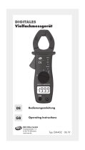
VOLTCRAFT VC 820-1 Operating Instructions Manual
- Category
- Measuring & layout tools
- Type
- Operating Instructions Manual
Page is loading ...

Diese Bedienungsanleitung gehört zu diesem Produkt. Sie enthält
wichtige Hinweise zur Inbetriebnahme und Hand habung. Achten Sie
hierauf, auch wenn Sie dieses Produkt an Dritte weitergeben.
Heben Sie deshalb diese Bedienungsanleitung zum Nach lesen auf!
Eine Auflistung der Inhalte finden Sie in dem Inhaltsverzeichnis mit Angabe
der entsprechenden Seitenzahlen auf Seite 5.
These Operating Instructions are part of the product. They contain
important information on commissioning and installation. Please follow
them, including when passing this product on to third parties.
Please keep the Operating Instructions for future reference!
The contents page on page 21 lists the contents of these instructions
together with the relevant page number.
Le présent mode d'emploi fait partie intégrante du produit. Il com-
porte des directives importantes pour la mise en service et la manipu-
lation de l’appareil. Tenir compte de ces remarques, même en cas de
transfert du produit à un tiers.
Conserver le présent mode d'emploi afin de pouvoir le consulter à tout
moment.
La table des matières se trouve à la page 37.
Deze gebruiksaanwijzing hoort bij dit product. Er staan belangrijke
aanwijzingen in betreffende de ingebruikname en gebruik, ook als u dit
product doorgeeft aan derden.
Bewaar deze handleiding zorgvuldig, zodat u deze later nog eens kunt nale-
zen!
U vindt een opsomming van de inhoud in de inhoudsopgave met aanduiding
van de paginanummers op pagina 53.
2
Page is loading ...
Page is loading ...
Page is loading ...
Page is loading ...
Page is loading ...
Page is loading ...
Page is loading ...
Page is loading ...
Page is loading ...
Page is loading ...
Page is loading ...
Page is loading ...
Page is loading ...
Page is loading ...
Page is loading ...
Page is loading ...
Page is loading ...
Page is loading ...

Introduction
Dear Customer,
In purchasing this Voltcraft® product, you have made a very good decision for which
we should like to thank you.
You have acquired an above-average quality product from a brand family which has
distinguished itself in the field of measuring, charging and network technology by
particular competence and permanent innovation. With Voltcraft®, you will be able
to cope even with difficult tasks as an ambitious hobbyist just as much as a profes-
sional user. Voltcraft® offers you reliable technology at an extraordinarily favourable
cost-performance ratio. We are certain: Your start with Voltcraft will at the same time
be the commencement of a long and profitable co-operation. We wish you much
enjoyment with your new Voltcraft® product!
If there are any technical questions, contact:
Germany: Tel. no.: +49 9604 / 40 88 80
Fax. no.: +49 9604 / 40 88 48
E-mail: [email protected]
Mon. to Thur. 8.00am to 4.30pm, Fri. 8.00am to 2.00pm
To maintain the specifications and to ensure risk-free operation, the user should
comply with the following operating instructions!
Intended Use
- Measuring direct voltages up to a maximum of 600VDC
- Measuring alternating voltages up to a maximum of 600VACrms
- Measuring direct or alternating currents up to a maximum of 20A, for a maximum
period of 10s with pauses of 15min between the single measurements
- Measuring capacities of up to a maximum of 100µF
- Measuring frequencies of up to 10MHz and measuring the pulse-pause-ratio (duty
cycle, informative)
- Measuring resistance values up to a maximum of 40 MOhm
- Testing diodes and checking the acoustic continuity
- Overvoltage category CAT III 600V
Use other than that described above will lead to damage to the measuring instru-
ment and additional risks, such as short circuit, fire, electric shock etc. No part of the
product may be changed or modified! The safety instructions should be observed
without fail!
21

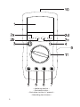
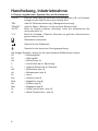
Control Elements
Illustration (foldout page)
1. 3
3
/
4
digit liquid crystal display (LCD) and display of functions and measuring units
2. Push-button panel with the function buttons 2a „RANGE“ (manual range selec-
tion),
2b „Hz %“ (switch-over from frequency measurement to duty cycle), 2 c „REL“
(relative = reference value measurement) and 2 d „HOLD H“ (hold on)
3. „POWER“ button for measuring instrument on / off
4. Buttons for the subfunctions
5. 20-A input This measuring input is secured by 10A (fuse) and has been
approved for the connection to direct and alternating currents of up to a maxi-
mum of 20A (for a max. period of 10s with pauses of 15min between the single
measurements).
6. mA/µA input At this input, direct and alternating currents of up to max. 400mA
can be measured (secured by a quick-acting 0,4A fuse).
7. Hz/V/ohm – input socket (positive connection)
8. COM – input socket (COM or negative connection)
9. Battery compartment cover with battery compartment below (rear side)
10. Serial RS - 232C - infrared interface (unidirectional) for the connection / the data
transfer to a PC
11. Rotary switch for setting the measuring functions
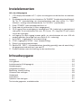
Table of Contents
Introduction . . . . . . . . . . . . . . . . . . . . . . . . . . . . . . . . . . . . . . . . . . . . . . . . . . . . . . . 21
Intended Use . . . . . . . . . . . . . . . . . . . . . . . . . . . . . . . . . . . . . . . . . . . . . . . . . . . . . .21
Control Elements (fold-out page) . . . . . . . . . . . . . . . . . . . . . . . . . . . . . . . . . . . . . . .22
Table of Contents . . . . . . . . . . . . . . . . . . . . . . . . . . . . . . . . . . . . . . . . . . . . . . . . . . .22
Safety Instructions . . . . . . . . . . . . . . . . . . . . . . . . . . . . . . . . . . . . . . . . . . . . . . . . . .23
Handling and Starting-up Operation . . . . . . . . . . . . . . . . . . . . . . . . . . . . . . . . . . . .24
Carrying out Measurements . . . . . . . . . . . . . . . . . . . . . . . . . . . . . . . . . . . . . . . . . . .27
Servicing and Maintenance . . . . . . . . . . . . . . . . . . . . . . . . . . . . . . . . . . . . . . . . . . .31
Disposal . . . . . . . . . . . . . . . . . . . . . . . . . . . . . . . . . . . . . . . . . . . . . . . . . . . . . . . . . .33
Troubleshooting . . . . . . . . . . . . . . . . . . . . . . . . . . . . . . . . . . . . . . . . . . . . . . . . . . . .33
Technical Data and Measuring Tolerances . . . . . . . . . . . . . . . . . . . . . . . . . . . . . . .34
22

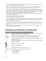
Safety Instructions
Damage due to non-compliance with these operating instructions leads to the expiry
of warranty! We accept no liability for consequent damage.
We accept no liability for damage to property or injury to persons caused by the mis-
handling of the device or non-compliance with the safety instructions. In such cases
the guarantee will lapse.
-
These devices have been designed in compliance with EN61010, safety require-
ments for electronic measuring instruments, and left the factory in perfect condition
in terms of safety engineering. To maintain this status and ensure safe operation,
the user must comply with the safety instructions and warnings contained in these
operating instructions.
Ꮨ
= Caution! Dangerous voltage, do not touch! Danger!
= Read the operating instructions!
CAT III = Excess voltage category III for measurements in the building
installation
= Insulation class 2 (double insulated)
- Measurements of currents are only permitted in such electric circuits which them-
selves are secured by 20A and in which the voltages do not exceed 600VAC or
VCD (600V fuse).
- The measuring instruments and circuits are not protected against electric arc
explosions.
- Measuring instruments and accessories should be kept out of the reach of children!
- In commercial institutions, the accident prevention regulations of the Employer’s
Liability Insurance Association for Electrical Systems and Operating Materials are
to be observed.
-
In schools, training centres, computer and self-help workshops, handling of measur-
ing instruments must be supervised by trained personnel in a responsible manner.
- Take particular care when dealing with voltages exceeding 25V alternating current
(AC) or 35V direct current (DC). Even at these voltages it is possible to get a fatal
electric shock if you touch electric conductors. Therefore, first de-energise the
voltage source, connect the measuring instrument to the connections at the volt-
age source to be measured, set the required voltage measurement range at the
measuring instrument, and then switch on the voltage source. When the measure-
ment has been completed, de-energise the voltage source and remove the cables
from the connections at the voltage source.
- Always make sure before measuring voltages that another measuring function is
not active (resistance measurement, diode test etc.).
23

- Before changing the measuring range, the test prods or adapters have to be
removed from the object to be measured.
- Check your measurement instrument or your measuring lines and adapters for
their correct functioning or for damage(s) before starting a measurement.
- Do not use the measuring instrument in rooms or at unfavourable ambient condi-
tions in which there may or could be combustible gases, vapours or dust. For your
own safety, always ensure that the measuring instrument and cables cannot
become wet or damp. Avoid operation in the immediate vicinity of:
a) magnetic and electromagnetic fields (transformers, motors, coils, relays, contac-
tors, electromagnets etc.)
b)electrostatic fields (charges/discharges)
These could falsify the value measured.
- For safety reasons, when measuring only use the supplied measuring cables
which are approved for the specifications of the measuring instrument. These are
the only cables permitted for use.
- To avoid an electric shock make sure that you do not touch the test prods or the
connections to be measured (measuring points), even indirectly, during measure-
ment.
- The voltage between any socket of the measuring instrument and the ground may
not be higher than 600V CAT III.
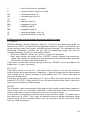
Handling and Starting-up Operation
A Display indications and symbols for the operating modes
„HOLD“ stands for Data Hold; the measuring value is kept (e.g. for the record)
until the HOLD button is pressed anew.
„REL“ stands for relative value measurement (= reference measurement)
„RANGE“ stands for (measuring) range; for the manual range selection.
„AUTO“ is indicated in the display (black background), if the automatic ran ge
selection is active.
„O.L.“ stands for overload. The measuring value is too high or the measuring
range is exceeded
Battery replacement symbol
Symbol for the diode test
Symbol for the acoustic continuity check
all other symbols standing for the different measuring units:
AC = alternating quantity
DC = direct quantity
mV = millivolt (exp.-3)
24

V = volt (unit of electric potential)
A = ampere (unit of electric current)
mA = milliampere (exp.-3)
µA = microampere (exp.-6)
Hz = Hertz
kHz = kilohertz (exp.3)
MHz = megahertz (exp.6)
kΩ = kiloohm (exp.3)
MΩ = megaohm (exp.6)
nF = nanofarad (nano = exp.-9)
µF = microfarad (micro = exp.-6)
B Button layout and functional description with key input
B 1 RANGE
RANGE bedeutet, wörtlich übersetzt, Bereich. It refers to the measuring range. As
soon as the „AUTO“ symbol (black background) becomes visible in the display, you
do not need to select the correct, adjusted measuring range. The intelligence of the
measuring instrument switches for you. But the measuring range can also be
changed manually. To do this, proceed as follows:
- Press the „RANGE“ button; the „AUTO“ symbol will disappear.
- Now, each further activation of the „RANGE“ button changes the measuring
range. This change is indicated by the movement of the decimal point and pos-
sibly by the change of the measuring unit.
If you want to leave the manual setting, press the „RANGE“ button and hold it for
longer than 1s (keep it pressed).
B 2 „Hz %“
If the rotary switch is set to „Hz“, this button will be relevant. You do not need this
button for the real measurement of frequency. If you like to indicate the pulse-pause
ratio instead of the normal frequency measurement (for TTL levels), you have to
press this button once.
Instead of the frequency indication in HZ, kHz or MHz, the pulse-pause ratio, also
called DUTY CYCLE, is indicated in % now. By pressing the button anew, you return
to the normal frequency measurement.
B 3 REL
The reference value measurement indicated by the triangle symbol allows measure-
ments which refer to a previously indicated / measured value. Now, the difference
value is indicated (current measuring value minus reference value).
This function is particularly useful for measuring resistance values. The main indica-
tion can be set to „0000“. Thus, you can measure values in the low-resistance range
without being forced to always reduce the line resistance of the instrument leads
from the value measured.
25

The reference value measurement is not possible for frequency and pulse-pause
ratio measurements. As the „AUTO“ range is turned off for the reference value mea-
surement, you have to select the desired measuring range manually before using this
special function. After leaving this extra function, press the „RANGE“ button once
and keep it pressed for longer than 1s to return to the automatic range selection
mode.
Example:
Proceed as follows to set the reference value:
Set the desired measuring range (via the RANGE button). Measure the required ref-
erence value, e.g. a direct voltage of 12VDC. Press the “REL” button once. If the
measuring prods are now disconnected from the voltage source, the value „DC -
12V“ will be indicated in the main display.
B 4 HOLD
The „HOLD H“ button is to be activated once, if you want to keep a test certificate for
example and want to record the current measuring value before it will change again.
By pressing the „HOLD“ button the current value is „frozen“ or kept. The „H“ symbol
in the header of the display is marked by a black background.
If you want to release the running measurement anew, activate the „HOLD H“ button
once again. The currently measured value will be displayed.
B 5 POWER (round)
The „POWER“ switch is used to switch the measuring instrument on and off.
B 6 second-function button (blue)
The second-function button is positioned top right of the rotary switch and is used to
turn on/off the blue-described measuring functions around the rotary switch. For
resistance measurements (ohm), each push on the button switches between the
diode test „ “, the continuity check „ “ and the resistance measurement. For
current and voltage measurements this button is used to change between direct (DC)
and alternating (AC) quantities.
B 7 rotary switch
The rotary switch sets the diverse measuring functions.
Warning!
The measurement function switch may never be reset in the course
of measurement, because this action could damage the measuring
instrument (breaking sparks) and consequently cause grave danger
for you if the voltages exceed 25VACrms or 35VDC.
26

Carrying out Measurements
Warning!
Always observe the maximum permissible input values! Observe the
safety instructions!
Measuring voltages
Proceed as follows to measure DC voltages up to max. 600VDC:
a) Connect the measuring lines to the measuring instrument turned off; ensure the
correct polarity. Connect the red measuring line to the Hz/V/ohm input and the
black measuring line to the „COM“ (= ground or „-“). Make sure they are plugged
properly.
b) Move the rotary switch to “V” and turn on the measuring instrument. After a short
initialisation phase (all segments are visible), the „AUTO“ function switches to the
lowest possible range of measurement (mV).
c) Connect the measuring prods to the object to be measured.
Press the blue second-function button for measuring AC voltages (up to max.
600VACrms).
Notes!
- Moreover, the following subfunctions can be set:
Holding the measuring value „HOLD H“, reference measurement „REL“ and
manual range selection „RANGE“.
- For open measuring lines it is possible that irrational values are indicated up
to 0.5V due to the high input sensitivity.
Measuring resistance values
Caution!
Make sure that all the circuit parts, switches and components as well as other
objects to be measured are disconnected from the voltage source at all times.
Proceed as follows to measure resistance values up to max. 40 MOhm:
a) Connect the measuring lines to the measuring instrument turned off; ensure the
correct polarity. The red measuring line is to be connected to the Hz/V/ohm input
and the black measuring line to the „COM“ (= ground or „-“). Make sure they are
plugged properly.
b) Move the rotary switch to „Ω“ and turn on the measuring instrument. After a short
initialisation phase (all segments are visible), the „AUTO“ function switches to the
highest possible range of measurement (MOhm).
c)
Connect the measuring prods to the absolutely voltage-free object to be measured.
Note(s)!
The following subfunctions can be set:
Holding the measuring value „HOLD H“, reference measurement „REL“ and
manual range selection „RANGE“.
27

Normally, the resistance of the measuring lines is so low (ca. 0.1 to 0.2 ohms)
that it can be neglected. However, this low resistance can even result in inac-
curate values within the 400 ohm measuring range.
Therefore, use the REL function to avoid the indication of the resistance of the
measuring lines.
For a resistance >1MΩ the electronic system needs a little bit of time to sta-
bilise the indication.
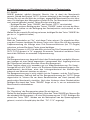
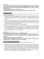
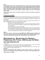
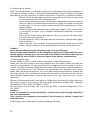
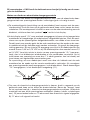
Testing diodes and checking the acoustic continuity
Proceed as follows to test diodes and semiconductor paths or to check the acoustic
continuity of voltage-free lines / fuses:
a) The measurement set-up (connection of the measuring lines) corresponds to the
one of the resistance measurement. Press the blue second-function button once.
Now, the measuring instrument switches from resistance measurement to diode
test, the „ “ symbol becomes visible on the right side of the display.
b) „.0L“ for overload is indicated for open or not connected measuring lines or for
high-resistance (or interrupted) semiconductor paths. Connect the measuring
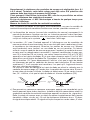
prods to the voltage-free semiconductor component, a diode or a transistor. When
doing this make sure that the red measuring line is connected to the anode and the
black measuring line to the cathode. Now, the forward direction is tested. If the p-
n-junction functions properly, a value of between 0.45 and 0.75VDC will be dis-
played for Si-diode paths and a value of between 0.2 and 0.4VDC will be shown for
Ge-diode paths. But if „.0L“ appears instead of a voltage value, the diode path is
interrupted or the measuring lines have been mixed up. If a voltage higher than 1V
is measured for transistors it is possibly a transistor with integrated resistors.
The reverse direction of a diode path is tested by connecting the cathode with the
red measuring line and the anode with the black measuring line. If a voltage value
is displayed now, the diode is defect. But if „.0L“ is indicated, it is a high-resis-
tance diode path (OK).
c) To switch to the acoustic continuity check, activate the blue second-function
switch top right of the rotary switch once more. Above the „ohm symbol“ the sym-
bol for the acoustic continuity check is displayed. Connect the measuring prod to
the absolutely voltage-free object to be measured (lines, cables, circuits etc.). An
audio signal is generated for resistance values below approximately 70 ohm. The
loudest signal is generated for „0“ ohm.
rote
Meßleitung
schwarze
Meßleitung
Durchlaßrichtung
rote
Meßleitung
schwarze
Meßleitung
Sperrichtung
28
red measuring
line
black measu-
ring line
red measuring
line
black mea-
suring line
load, switch reverse direction

Measuring the capacity
Caution!
Discharge each capacitor before connecting it to the measuring instrument. If
capacitors are short-circuited, high-energy discharges can be caused. Do not
touch the connections of capacitors with voltages above 35VDC or 25VAC. Pro-
ceed with caution. DANGER!
Never carry out measurements at capacitors which are installed into cir-
cuits/circuit components.
Proceed as follows to measure unipolar (electrolytic capacitors) and bipolar capacitors:
a) The measurement set-up (connection of the measuring lines) corresponds to the
one used for the resistance measurement. For the VC-820, set the rotary switch to
position „ “.
b) Now connect the measuring prods to the capacitor. Observe the „+“ and „-“
(polarity) when measuring electrolytic capacitors. Ensure that the connections are
sufficiently long and clean.
Notes!
If the capacity is measured, residual capacities of up to 1.5nF can be indicated
even if no capacitor is connected. Therefore, it is recommended to set the indi-
cation to zero by pressing the „REL“ button before starting the measurement.
The following subfunctions can be set:
Holding the measuring value „HOLD H“ and reference measurement „REL“.
Measuring frequencies
Proceed as follows to measure the frequency of sinusoidal alternating voltages up to
max. 10MHz:
a) Connect the measuring lines to the measuring instrument turned off; ensure the
correct polarity. The red measuring line is to be connected to the Hz/V/ohm input
and the black measuring line to the „COM“ (= ground or „-“). Make sure they are
plugged properly.
b) Move the rotary switch to “Hz” and turn on the measuring instrument. After a short
initialisation phase (all segments are visible), the measuring instrument automati-
cally switches to the lowest possible range of measurement. A manual range
selection is not possible when measuring frequencies.
c) Connect the measuring prods to the object to be measured.
d) If you like to activate the informative pulse-pause ratio indication for TTL levels in
% instead of the normal frequency indication in „Hz“ (kHz, MHz), you have to
press the „Hz %“ button once. Now, the indication theoretically ranges up to
99.9% with a maximum resolution of 0.1%. You return to the frequency measure-
ment by pressing the „Hz %“ button once more.
29

Caution!
Never exceed the max. input values!
For voltages lower than 300mVrms (measured at 1 kHz) up to 1MHz a frequency
measurement cannot be performed, and for voltages lower than 600mVrms from
above 1 MHz up to < 10MHz a frequency measurement cannot be performed.
Notes!
The following subfunctions can be set:
Holding the measuring value „HOLD H“ and switch-over from „Hz“ (frequency
measurement) up to „%“ (pulse pause ratio measurement).
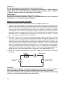
Measuring direct and alternating currents
Proceed as follows to measure AC/DC currents:
a) Connect the measuring lines to the measuring instrument turned off; ensure the
correct polarity. Depending on the current range you select for your measurement
(µA, mA, A), the measuring lines are to be connected differently to the measuring
instrument. The red measuring line is to be connected to the „µA/mA“ socket for
measurements in the range of between 0 and 4000µA or between 0 and 400mA
and for measurements in the range from 0.4A to 20A it is to be plugged into the
„20A“ socket. The black measuring line is to be connected to „COM“ (= ground or
„-“). Make sure they are plugged in properly.
b) Depending on the current values you want to measure, move the rotary switch to
„µA“, „mA“ or „A“ and turn on the measuring instrument. After a very brief initialisa-
tion phase (all segments), the direct current measurement is turned on now. To be
able to measure alternating currents, press the blue second-function switch top
right of the rotary switch once. Then, the symbol of the alternating quantities „AC“ (=
alternating current) is displayed left to the value measured. Moreover, the automatic
range selection, indicated by „AUTO“, is active. That means that the lowest possible
range of measurement is set with a resolution of 0.1µA.
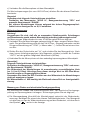
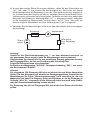
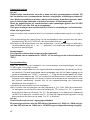
c)
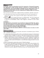
Connect the measuring lines in series to the object to be measured (see following
figure).
Caution!
If for DC measurements a minus „-“ appears in front of the value measured, the
measured current is negative (or the measuring lines have been mixed up).
Never exceed the maximum input values of the input used, because this could
destroy the fuse.
The following subfunctions can be set:
Holding the measuring value „HOLD H“, reference measurement „REL“ and
manual range selection „RANGE“.
30
ammeter
fuse
consumer
load, switch
A
power
source
~

Note!
The integrated 10A fuse can be checked in an easy way: Set the measuring
instrument to the acoustic continuity check (see „Measuring resistance values“
for connecting the measuring lines) and connect the measuring prod to the 20A
input. If an audio signal is generated, the fuse is OK. If „0L.“ is indicated, the
fuse is defect and has to be replaced. When doing this, observe the safety
instructions.
If you want to check a fuse of the μA/ mA-input, it will be necessary to open the
instrument.
Connecting a computer
The optoelectronic unidirectional (into one direction) interface to a PC in form of an
IR diode is positioned at the top of the rear side of the measuring instrument. The
serial interface is always active, indicated by the „RS232C“ symbol in the header of
the display.
The following steps are to be performed to allow the communication between an
(IBM-compatible) PC and your measuring instrument:
- Switch off the measuring instrument.
-
The interface is integrated at the rear side. Turn over the measuring instrument.
- Take the interface line and slide the coupler into the wedge-shaped recess
up to the stop.
- The connection has been established.
-
The transmission is performed in an unidirectional manner (into one direction).
- Load the DEMO software (from Windows ‘95) by using the explorer (Setup
or Install) of your PC (from Pentium I) and follow the instructions displayed,
or do it via Autostart (CD inserted, at start of Windows).
Notes!
The main memory must have at least 8MB. The DEMO software additionally
requires a memory space of approximately 8MB on the hard disc. Moreover, a
free serial interface is necessary. The transmission rate is 2400 bauds.
Maintenance, Replacing the Battery,
Replacing the Fuses, Setting up the Mea-
suring Instrument
a General
To ensure the accuracy of the multimeters over a longer period of time, they should
be calibrated once a year, possibly in our calibration laboratory.
To clean the devices or the display window and measurement lines, use a clean, lint-
free anti-static and dry cleaning cloth.
Caution!
Do not use detergent that contains carbon, petrol, alcohol or similar sub-
stances for cleaning purposes. Otherwise, the surface of the measuring instru-
ments will be corroded.
31

b Replacing the battery
A 9V compound battery is required to operate the individual measuring instrument. If
the replace battery symbol is displayed approximately 8 hours before the battery
goes dead, it will be necessary to replace the battery. To do this, proceed as follows:
- Switch off the measuring instrument by separating it from the measuring
circuit and disconnect the measuring lines.
- Unscrew the fastening screw of the battery compartment (centre screw at
the rear side of the measuring instrument) by using a suitable screwdriver
(crosshead). It is not necessary to open the device completely for replac-
ing the battery.
- Remove the battery compartment by drawing it slightly. The (used) battery
is secured by a clamp. Use a suitable crosshead screwdriver to remove
this clamp.
- Take out the used battery and replace it by a new one of the same type.
Pay attention to the polarity!
- Fix the clamp till it locks into place and put the battery compartment again
onto the device.
-
Now, close the cover carefully. During the replacement make sure that the
battery contact springs in the measuring instrument will not be deformed.
Caution!
Never operate the measuring instrument when it is open! Danger!
Do not leave used batteries in the measuring instrument. Even batteries pro-
tected against leaking may corrode and thus release chemicals that may be
detrimental to your health or they may destroy the battery compartment.
c Replacing the fuses
Always adhere carefully to the safety instructions, if you replace fuses!
Make sure that only fuses of the type stated and of the rated current specified are
used as a replacement. Using repaired fuses or bridging the fuse bracket is not per-
mitted. To replace the fuses disconnect the measuring instrument from the measure-
ment circuit and switch it off. Remove all connected lines, adapters and testing
prods from the measuring device. Use a suitable crosshead screwdriver to open the
housing carefully. First, remove the cover with the battery and then unscrew the last
two recessed head screws. Remove the lower cover part; now the fuses can be
accessed.
Remove the defective fuse(s) and replace it (them) by a fuse (fuses) of the same type
and rated current. For the fuse of the mA-range: 0.4A quick-acting, 600V; common
designation: F0,4A / 600V or F400mA / 600V
For the fuse of the A-range: 10A, quick-acting, 600V; common designation: F10A
LAC 600V.
Caution!
Close and fasten the hosing carefully in reverse order after having completed
the fuse replacement.
Only operate the measuring instrument if the housing is reliably closed and
screwed down.
d Setting up the measuring instrument (diagonal position)
32

The measuring instrument has a fold-out stand on the rear side. You can use this
stand to move the measuring instrument into a diagonal position; thus it is easier to
read the display.
Disposal
a) Product
Electronic devices are recyclable waste materials and must not be disposed
of in the household waste!
Dispose of an unserviceable product in accordance with the relevant statu-
tory regulations.
Remove the battery if there is one inserted and dispose of it separately from
the product.
b) Normal and Rechargeable Batteries
As the end user, you are required by law (Battery Regulation) to return used batteries
and rechargeable batteries. Do not dispose of used batteries in the household waste!
Batteries/rechargeable batteries contain harmful materials and are labelled
with the symbol shown to indicate that disposal in the household waste is
forbidden. The symbols of the relevant heavy metals are: Cd=cadmium,
Hg=mercury, Pb=lead (marking can be seen on the battery/rechargeable
battery, e.g. underneath the refuse bin symbol shown on the left).
You can return your used batteries/rechargeable batteries free of charge at the offi-
cial collection points of your community, in our stores, or anywhere batteries or
rechargeable batteries are sold!
You thereby fulfil your statutory obligations and contribute to the protection of the
environment.
Troubleshooting
With this digital multimeter, you have purchased a product constructed in accor-
dance with the latest state of the art. Problems and disturbances may, however, still
arise. Therefore, there follows a description of how to eliminate some of these faults
relatively easily yourself. Do not fail to observe the safety instructions!
Fault Possible cause
No measurement possible Are the measuring lines correctly connected to the
measuring sockets?
Do the fuses work properly?
No display appears Is the battery flat?
if the device is turned on
Frequency measurement Is the measuring voltage (amplitude) sufficiently high
not possible (> 300mVeff or 600mVeff)?
33

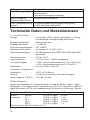
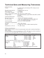
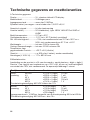
Technical Data and Measuring Tolerances
A Technical data
Display . . . . . . . . . . . . . . . . : 3
3
/
4
digit liquid crystal display (LCD), display size of
4000 counts
Speed of measurement . . . : 3 measurements per sec.
Input resistance . . . . . . . . . : > 10 MOhm
Over-voltage category. . . . : CAT III 600V
Battery replacement symbol: from lower than 7.5VDC ±0,5V
Voltage supply . . . . . . . . . . : 9V compound battery, type: NEDA 1604 6F22 or 006P
or 6LR61
Operating temperature . . . : 0°C to +40°C
Storage temperature . . . . . : -10°C to +50°C (batteries removed)
Rel. air humidity. . . . . . . . . : < 75%, non-condensing from 0°C to +30°C and
< 50%, non-condensing from 31°C to 40°C
Operating height . . . . . . . . : up to max. 2,000m above MSL
Temperature for guaranteed
accuracy . . . . . . . . . . . . . . : +23°C ±5K (=Kelvin)
Weight . . . . . . . . . . . . . . . . : ca. 300g (with battery, without measuring lines)
Dimensions (L x W x H) . . . : 177 x 85 x 40mm
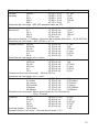
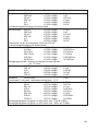
B Measuring tolerances
Indication of accuracy in ±(% of the measurement value read + number of positions =
digits =dgt(s)).
Accuracy valid for 1 year at a temperature of +23°C ±5K, and at a relative humidity of
less than 75%, non-condensing. The warm-up time is 1 minute
Operating mode Measurement range Accuracy Resolution
Direct 400mV ±(1.0% + 5 dgts) 0.1mV
voltage 4V ±(0.9% + 5 dgts) 1mV
40V ±(0.9% + 5 dgts) 10mV
400V ±(0.9% + 5 dgts) 100mV
600V ±(1.4% + 5 dgts) 1V
Overload protection: 600VDC lower than 10s
Alternating For input voltages < 50mV not specified
voltage 4V ±(1.5%+5dgts) 1mV
40V ±(1.5%+5dgts) 10mV
400V ±(1.0%+5dgts) 100mV
600V ±(2%+5dgts) 1V
Input resistance > 10 MOhm, frequency of the alternating voltage: 50Hz to 400Hz
Overload protection: 600VACrms < 10s
34

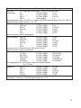
Operating mode Measurement range Accuracy Resolution
Direct current 400µA ±(1.0%+5dgts) 0.1µA
4000µA ±(1.0%+5dgts) 1µA
40mA ±(1.2%+5dgts) 0.01mA
400mA ±(1.2%+5dgts) 0.1mA
4A ±(1.5%+5dgts) 0.001A
20A ±(1.5%+5dgts) 0.01A
Overload protection see below
Alternating current 400µA ±(2.0%+5dgts) 0.1µA
4000µA ±(2.0%+5dgts) 1µA
40mA ±(2.0%+5dgts) 0.01mA
400mA ±(2.0%+5dgts) 0.1mA
4A ±(2.5%+5dgts) 0.001A
20A ±(2.5%+5dgts) 0.01A
Frequency of the alternating current: 50Hz to 400Hz
Overload protection see below
Resistance 400 ohm ±(1.2%+2dgts) 0.1 ohm
4kohm ±(1.0%+2dgts) 0.001kohm
40kohm ±(1.0%+2dgts) 0.01kohm
400kohm ±(1.0%+2dgts) 0.1kohm
4 MOhm ±(1.2%+2dgts) 0.001MOhm
40 MOhm ±(1.5%+2dgts) 0.01MOhm
Continuity tester: acoustic signal for resistance values
< ca. 70 ohm
Capacity 40nF ±(3.0%+10dgts) 0.01nF
C 400nF ±(3.0%+5dgts) 0.1nF
4µF ±(3.0%+5dgts) 0.001µF
40µF ±(3.0%+5dgts) 0.01µF
100µF ±(4.0%+5dgts) 0.1µF
Diode test Ge to GaAs 1mV
Test voltage 1mA max.; emitter diode voltage max. 1.5V
Frequency 5Hz ±(0.1%+3dgts) 0.001Hz
50Hz ±(0.1%+3dgts) 0.01Hz
500Hz ±(0.1%+3dgts) 0.1Hz
5kHz ±(0.1%+3dgts) 0.001kHz
50kHz ±(0.1%+3dgts) 0.01kHz
500kHz ±(0.1%+3dgts) 0.1kH
5MHz ±(0.1%+3dgts) 0.001MHz
10MHz ±(0.1%+3dgts) 0.01MHz
Sensitivity higher or equal to ca. 300mVeff from 1Hz to 1MHz
Sensitivity higher or equal to ca. 600mVeff from 1MHz to 10MHz
35

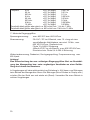
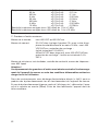
C Maximum input values
Voltage measurement: max. 600VDC or 600VACrms
Current measurement: 20A AC / DC in the A-range, for max. 10s with a subse-
quent cool-down phase of min. 15min., max.
600VDC/VACrms, overload protection:
quick-acting 10A-600V fuse
400mA AC/DC in the mA-range, max. 600VDC/VACrms,
overload protection: quick-acting 0.4A-250V fuse
Resistance measurement, diode test, continuity check, frequency measurement:
max. 600Vpeak
Caution!
If the maximum permissible input values are exceeded, the measuring instru-
ment will be damaged and under unfavourable conditions the user’s life will be
endangered seriously.
In an environment with high electrostatic discharges (± 4kV), malfunctions can be
caused when the measuring instrument is used. In case of malfunctions (irrational
characters in the display etc.) switch off the device and then switch it on again
(reset). Avoid the use of the instrument under such conditions.
36
Page is loading ...
Page is loading ...
Page is loading ...
Page is loading ...
Page is loading ...
Page is loading ...
Page is loading ...
Page is loading ...
Page is loading ...
Page is loading ...
Page is loading ...
Page is loading ...
Page is loading ...
Page is loading ...
Page is loading ...
Page is loading ...
Page is loading ...
Page is loading ...
Page is loading ...
Page is loading ...
Page is loading ...
Page is loading ...
Page is loading ...
Page is loading ...
Page is loading ...
Page is loading ...
Page is loading ...
Page is loading ...
Page is loading ...
Page is loading ...
Page is loading ...
Page is loading ...
Page is loading ...
Page is loading ...
Page is loading ...
Page is loading ...
Page is loading ...

Impressum
Diese Bedienungsanleitung ist eine Publikation der Conrad Electronic SE, Klaus-Conrad-Str. 1,
D-92240 Hirschau (www.conrad.com).
Alle Rechte einschließlich Übersetzung vorbehalten. Reproduktionen jeder Art, z. B. Fotokopie,
Mikroverfilmung, oder die Erfassung in elektronischen Datenverarbeitungsanlagen, bedürfen der
schriftlichen Genehmigung des Herausgebers. Nachdruck, auch auszugsweise, verboten.
Diese Bedienungsanleitung entspricht dem technischen Stand bei Drucklegung. Änderung in Tech-
nik und Ausstattung vorbehalten.
© Copyright 2014 by Conrad Electronic SE.
Legal Notice
These operating instructions are a publication by Conrad Electronic SE, Klaus-Conrad-Str. 1,
D-92240 Hirschau (www.conrad.com).
All rights including translation reserved. Reproduction by any method, e.g. photocopy, microfilming,
or the capture in electronic data processing systems require the prior written approval by the editor.
Reprinting, also in part, is prohibited.
These operating instructions represent the technical status at the time of printing. Changes in tech-
nology and equipment reserved.
© Copyright 2014 by Conrad Electronic SE.
Informatin légales
Ce mode d‘emploi est une publication de la société Conrad Electronic SE, Klaus-Conrad-Str. 1, D-
92240 Hirschau (www.conrad.com).
Tous droits réservés, y compris de traduction. Toute reproduction, quelle qu‘elle soit (p. ex. photo-
copie, microfilm, saisie dans des installations de traitement de données) nécessite une autorisation
écrite de l‘éditeur. Il est interdit de le réimprimer, même par extraits. Ce mode d‘emploi correspond
au niveau technique du moment de la mise sous presse. Sous réserve de modifications techniques
et de l‘équipement.
© Copyright 2014 by Conrad Electronic SE.
Colofon
Deze gebruiksaanwijzing is een publicatie van de firma Conrad Electronic SE, Klaus-Conrad-Str. 1,
D-92240 Hirschau (www.conrad.com).
Alle rechten, vertaling inbegrepen, voorbehouden. Reproducties van welke aard dan ook, bijvoor-
beeld fotokopie, microverfilming of de registratie in elektronische gegevensverwerkingsapparatu-
ur, vereisen de schriftelijke toestemming van de uitgever. Nadruk, ook van uittreksels, verboden.
Deze gebruiksaanwijzing voldoet aan de technische stand bij het in druk bezorgen. Wijziging van
techniek en uitrusting voorbehouden.
© Copyright 2014 by Conrad Electronic SE.
V4_0314_01/HD
-
 1
1
-
 2
2
-
 3
3
-
 4
4
-
 5
5
-
 6
6
-
 7
7
-
 8
8
-
 9
9
-
 10
10
-
 11
11
-
 12
12
-
 13
13
-
 14
14
-
 15
15
-
 16
16
-
 17
17
-
 18
18
-
 19
19
-
 20
20
-
 21
21
-
 22
22
-
 23
23
-
 24
24
-
 25
25
-
 26
26
-
 27
27
-
 28
28
-
 29
29
-
 30
30
-
 31
31
-
 32
32
-
 33
33
-
 34
34
-
 35
35
-
 36
36
-
 37
37
-
 38
38
-
 39
39
-
 40
40
-
 41
41
-
 42
42
-
 43
43
-
 44
44
-
 45
45
-
 46
46
-
 47
47
-
 48
48
-
 49
49
-
 50
50
-
 51
51
-
 52
52
-
 53
53
-
 54
54
-
 55
55
-
 56
56
-
 57
57
-
 58
58
-
 59
59
-
 60
60
-
 61
61
-
 62
62
-
 63
63
-
 64
64
-
 65
65
-
 66
66
-
 67
67
-
 68
68
-
 69
69
-
 70
70
-
 71
71
-
 72
72
-
 73
73
-
 74
74


VOLTCRAFT VC 820-1 Operating Instructions Manual
- Category
- Measuring & layout tools
- Type
- Operating Instructions Manual
Ask a question and I''ll find the answer in the document
Finding information in a document is now easier with AI
in other languages
- français: VOLTCRAFT VC 820-1
- Deutsch: VOLTCRAFT VC 820-1
- Nederlands: VOLTCRAFT VC 820-1
Related papers
-
VOLTCRAFT VC-440 E Operating Instructions Manual
-
-
-
-
-
-
-
-
-
Other documents
-
 REV Ritter 0037400002 Owner's manual
-
Extech Instruments 382860 User manual
-
Basetech FM-10 Owner's manual
-
Laserliner MultiMeter Pocket XP Owner's manual
-
Laserliner MultiMeter-Compact Owner's manual
-
Laserliner MultiMeter-Home Owner's manual
-
Aktakom ATK-2021B User manual
-
Laserliner ClampMeter XP Owner's manual
-
LIVARNO Double Air Bed Operating instructions
-
Laserliner MultiClamp-Meter Owner's manual
