Teledyne Insta Trans-XD User manual
- Category
- Oxygen Equipment
- Type
- User manual

Teledyne Analytical Instruments i
OPERATING INSTRUCTIONS FOR
INSTA TRANS-XD
Trace and Percent Oxygen Digital
Transmitter
DANGER
Toxic gases and or flammable liquids may be present in this monitoring system.
Personal protective equipment may be required when servicing this instrument.
Hazardous voltages exist on certain components internally which may persist
for a time even after the power is turned off and disconnected.
Only authorized personnel should conduct maintenance and/or servicing.
Before conducting any maintenance or servicing, consult with authorized
supervisor/manager.
P/N M82620
6-16-14

Insta Trans-XD
Teledyne Analytical Instruments ii
Copyright © 2014 Teledyne Analytical Instruments
All Rights Reserved. No part of this manual may be reproduced, transmitted, transcribed,
stored in a retrieval system, or translated into any other language or computer language in
whole or in part, in any form or by any means, whether it be electronic, mechanical,
magnetic, optical, manual, or otherwise, without the prior written consent of Teledyne
Analytical Instruments, 16830 Chestnut Street, City of Industry, CA 91748.
Warranty
This equipment is sold subject to the mutual agreement that it is warranted by us free from
defects of material and of construction, and that our liability shall be limited to replacing or
repairing at our factory (without charge, except for transportation), or at customer plant at
our option, any material or construction in which defects become apparent within one year
from the date of shipment, except in cases where quotations or acknowledgements provide
for a shorter period. Components manufactured by others bear the warranty of their
manufacturer. This warranty does not cover defects caused by wear, accident, misuse,
neglect or repairs other than those performed by Teledyne or an authorized service center.
We assume no liability for direct or indirect damages of any kind and the purchaser by the
acceptance of the equipment will assume all liability for any damage which may result from
its use or misuse.
We reserve the right to employ any suitable material in the manufacture of our apparatus,
and to make any alterations in the dimensions, shape or weight of any parts, in so far as
such alterations do not adversely affect our warranty.
Important Notice
This instrument provides measurement readings to its user, and serves as a tool by which
valuable data can be gathered. The information provided by the instrument may assist the user
in eliminating potential hazards caused by his process; however, it is essential that all
personnel involved in the use of the instrument or its interface, with the process being
measured, be properly trained in the process itself, as well as all instrumentation related to it.
The safety of personnel is ultimately the responsibility of those who control process
conditions. While this instrument may be able to provide early warning of imminent
danger, it has no control over process conditions, and it can be misused. In particular, any
alarm or control systems installed must be tested and understood, both as to how they
operate and as to how they can be defeated. Any safeguards required such as locks, labels,
or redundancy, must be provided by the user or specifically requested of Teledyne at the
time the order is placed.
Therefore, the purchaser must be aware of the hazardous process conditions. The purchaser
is responsible for the training of personnel, for providing hazard warning methods and
instrumentation per the appropriate standards, and for ensuring that hazard warning devices
and instrumentation are maintained and operated properly.
Teledyne Analytical Instruments, the manufacturer of this instrument, cannot accept
responsibility for conditions beyond its knowledge and control. No statement expressed or
implied by this document or any information disseminated by the manufacturer or its
agents, is to be construed as a warranty of adequate safety control under the user’s process
conditions.

Oxygen Transmitter
Teledyne Analytical Instruments iii
Specific Model Information
The instrument for which this manual was supplied may
incorporate one or more options not supplied in the standard instrument.
Commonly available options are listed below, with check boxes. Any
that are incorporated in the instrument for which this manual is supplied
are indicated by a check mark in the box.
Instrument Serial Number: _______________________
Cell Class:
B1 B2C A2C
A5 L2C Insta-Trace Other
Insta Trans-XD Transmitter Model:

Insta Trans-XD
Teledyne Analytical Instruments iv
Safety Messages
Your safety and the safety of others are very important. We have
provided many important safety messages in this manual. Please read
these messages carefully.
A safety message alerts you to potential hazards that could hurt you
or others. Each safety message is associated with a safety alert symbol.
These symbols are found in the manual and inside the instrument. The
definition of these symbols is described below:
GENERAL WARNING/CAUTION: Refer to the instructions for
details on the specific danger. These cautions warn
of specific procedures which if not followed could
cause bodily Injury and/or damage the instrument.
CAUTION: HOT SURFACE WARNING: This warning is specific to
heated components within the instrument. Failure to
heed the warning could result in serious burns to
skin and underlying tissue.
WARNING: ELECTRICAL SHOCK HAZARD: Dangerous voltages appear
within this instrument. This warning is specific to
an electrical hazard existing at or nearby the
component or procedure under discussion. Failure
to heed this warning could result in injury and/or
death from electrocution.
Technician Symbol: All operations marked with this symbol are to be
performed by qualified maintenance personnel only.
NOTE: Additional information and comments regarding a
specific component or procedure are highlighted in
the form of a note.
CAUTION: THE ANALYZER SHOULD ONLY BE USED ONLY
FOR THE PURPOSE AND IN THE MANNER
DESCRIBED IN THIS MANUAL.
No
Symbol

Oxygen Transmitter
Teledyne Analytical Instruments v
IF YOU USE THE ANALYZER IN A MANNER OTHER
THAN THAT FOR WHICH IT WAS INTENDED,
UNPREDICTABLE BEHAVIOR COULD RESULT
POSSIBLY ACCOMPANIED WITH HAZARDOUS
CONSEQUENCES.
This manual provides information designed to guide you through
the installation, calibration operation and maintenance of your new
analyzer. Please read this manual and keep it available.
Occasionally, some instruments are customized for a particular
application or features and/or options added per customer requests.
Please check the front of this manual for any additional information in
the form of an Addendum which discusses specific information,
procedures, cautions and warnings that may be peculiar to your
instrument.
Manuals do get lost. Additional manuals can be obtained from
Teledyne at the address given in the Appendix. Some of our manuals are
available in electronic form via the internet. Please visit our website at:
www.teledyne-ai.com.

Insta Trans-XD
Teledyne Analytical Instruments vi
Safety Information
WARNING: Substitution of components may impair intrinsic
safety.
WARNING: To prevent ignition of flammable or combustible
atmospheres, read, understand and adhere to the
manufacturer’s live maintenance procedures.
WARNING: Potential electrostatic charging hazard.
The enclosure contains plastic. To prevent the risk of
electrostatic sparking the plastic surface should be
cleaned only with a damp cloth.
WARNING: The apparatus enclosure contains aluminum and is
considered to constitute a potential risk of ignition by
impact or friction. Care must be taken into account
during installation and use to prevent impact or
friction.

Oxygen Transmitter
Teledyne Analytical Instruments vii
DANGER
COMBUSTIBLE GAS USAGE
WARNING
This is a general purpose instrument designed for use in a
nonhazardous area. It is the customer's responsibility to
ensure safety especially when combustible gases are being
analyzed since the potential of gas leaks always exist.
The customer should ensure that the principle of operating
of this equipment is well understood by the user. Misuse of
this product in any manner, tampering with its components,
or unauthorized substitution of any component may
adversely affect the safety of this instrument.
Since the use of this instrument is beyond the control of
Teledyne, no responsibility by Teledyne, its affiliates, and
agents for damage or injury from misuse or neglect of this
equipment is implied or assumed.
ATEX Certification and Special Conditions for
Safe Use
Symbol X:
Warning! This instrument is not designed for use with
oxygen enriched gases, i.e. gases with an oxygen content
greater than 21%.

Insta Trans-XD
Teledyne Analytical Instruments viii
Warning! This instrument uses an aluminum case. Protect
against impact or friction to minimize ignition risks. Clean
with a damp cloth to prevent electrostatic discharge, and
must not be installed where it could be subjected to high
airflow dust laden atmospheres.
The electrical connections are not isolated from ground. This
must be taken into account during installation and use.

Oxygen Transmitter
Teledyne Analytical Instruments ix
Table of Contents
Specific Model Information .......................................................... iii
Safety Messages .......................................................................... iv
Safety Information ........................................................................ vi
ATEX Certification Special Conditions for Safe Use ................ vii
List of Figures ............................................................................... xi
Introduction ................................................................................... 1
1.1 Overview 1
1.2 Typical Applications 1
1.3 Main Features of the Transmitter 1
1.4 Operator Interface 2
Operational Theory ....................................................................... 5
2.1 Introduction 5
2.2 Oxygen Sensor 5
2.2.1 Principles of Operation 5
2.2.2 Anatomy of a Micro-fuel Cell 6
2.2.3 Electrochemical Reactions 7
2.2.4 The Effect of Pressure 8
2.2.5 Calibration Characteristics 8
2.3 Sample System 10
2.4 Electronics and Signal Processing 11
Installation ................................................................................... 13
3.1 Unpacking the Transmitter 13
3.2 Mounting the Transmitter 13
3.3 Gas Connections 13
3.4 Electrical Connections 15
3.5 Installing the Oxygen Sensor 16

Insta Trans-XD
Teledyne Analytical Instruments x
3.6 Powering UP and Testing the System 17
Operation ..................................................................................... 19
4.1 Introduction 19
4.2 The Range and Calibration Functions 19
4.3 Range Selection 20
4.4 Calibration 20
4.4.1 Span Calibration 21
4.4.2 4-20 mA Adjustment 21
4.5 Cold Boot 22
Maintenance ................................................................................ 25
5.1 Routine Maintenance 25
5.2 Cell Replacement 25
5.2.1 Storing and Handling Replacement Cells 25
5.2.2 When to Replace a Cell 26
5.2.3 Removing the Oxygen Sensor 26
5.2.4 Cell Warranty 27
5.3 Insta-Trace Sensor 28
Appendix ...................................................................................... 31
Specifications 31
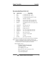
Recommended Spare Parts List 33
Drawings 34

Oxygen Transmitter
Teledyne Analytical Instruments xi
List of Figures
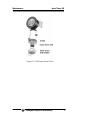
Figure 1-1: Insta Trans-XD User Interface ....................................... 3
Figure 2-1: Micro-fuel Cell ............................................................... 6
Figure 2-2: Cross Section of a Micro-fuel Cell (not to scale) ........... 7
Figure 2-3: Characteristic Input/Output Curve for a Micro-fuel Cell ....... 9
Figure 2-4: Gas and Power/Signal Connections to the Transmitter10
Figure 2-5: Insta Trans-XD Internal Electronics ............................. 11
Figure 2-6: Electronics Block Diagram .......................................... 12
Figure 3-1: Insta Trans-XD Connections and Mounting
Dimensions ................................................................. 14
Figure 5-1: Cell Removal ............................................................... 28
Figure 5-2: Cell Removal Insta-Trace ............................................ 30

Insta Trans-XD
Teledyne Analytical Instruments xii
[This page is intentionally blank]

Oxygen Transmitter Introduction
Teledyne Analytical Instruments 1
Introduction
1.1 Overview
The Teledyne Analytical Instruments Insta Trans-XD Oxygen
Digital Transmitter is a versatile instrument for measuring the oxygen
content in a gas sample. This manual covers the Insta Trans-XD Oxygen
Digital Transmitter. These units are rated Intrinsically Safe (IS) when
installed per the Interconnection Diagram D86181 (see Appendix) and
may be used in hazardous environments.
1.2 Typical Applications
A few typical applications of the Insta Trans-XD are:
Monitoring inert gas blanketing
Air separation and liquefaction
Chemical reaction monitoring
Semiconductor manufacturing
Petrochemical process control
Quality assurance
Gas analysis certification.
1.3 Main Features of the Transmitter
The Insta Trans-XD Oxygen Transmitter is sophisticated yet simple
to use. The main features of the analyzer include:
Digital microprocessor based analyzer.
3½ digit LCD display with range and calibration
annunciators.
User settable analysis range from 0-1 ppm through 0-25%
(sensor dependent).

Introduction Insta Trans-XD
Teledyne Analytical Instruments 2
Stainless steel cell block.
Simple push-button calibration and range selection.
Advanced trace or percent oxygen sensor has a one-year
warranty and an expected lifetime of two years.
Air-calibration range for convenient spanning at 20.9 %.
True 2-wire 4-20 mA powered loop interface.
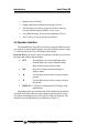
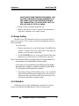
1.4 Operator Interface
The standard Insta Trans-XD is housed in a rugged NEMA-4 metal
case with all switches and the display accessible from the outside. Figure
1-1 illustrates the Insta Trans-XD display and switches.
Function Keys: Four touch-sensitive membrane switches are used to set
the range and calibrate the transmitter.
ENT Pressing Enter once selects the Range mode.
Pressing Enter twice enters Calibration mode.
Enter is also used to accept user input.
ESC Rejects user input and returns display to
Analyze mode.
▲ Used to adjust input values or range selection
upward.
▼ Used to adjust input values or range selection
downward.
DISPLAY 3 1/2 digit O
2
concentration LCD display with
annunciators
Depending on the operational mode of the instrument, the display
will blink and a final character at the rightmost position of the screen
will appear informing the user of the specific mode and function. The
characters used and the function are indicated in Table 1-1.

Oxygen Transmitter Introduction
Teledyne Analytical Instruments 3
Table 1-1: Function and Display Indicator
Function Display Indicator
Range
0-1 ppm
through 0-25%
(user defined)
No indicator (display not blinking)
analysis mode
R (Range setting mode) display blinking
P (Percent value)
Calibration
Span S (display blinking)
4-20 mA Adjust
4.00 (low end) L (display blinking)
20.0 (high end) H (display blinking)
Figure 1-1: Insta Trans-XD User Interface

Introduction Insta Trans-XD
Teledyne Analytical Instruments 4
[This page is intentionally blank]

Oxygen Transmitter Operational Theory
Teledyne Analytical Instruments 5
Operational Theory
2.1 Introduction
The transmitter is composed of three subsystems:
1. Oxygen Sensor
2. Sample System
3. Electronic Signal Processing, Display and Control
The sample system is designed to accept the sample gas and
transport it through the transmitter without contaminating or altering the
sample prior to analysis. The sensor is a micro-fuel cell which is an
electrochemical galvanic device that translates the amount of oxygen
present in the sample into an electrical current. The electronic signal
processing, display and control circuits simplify operation of the
transmitter and accurately displays the sampled data.
2.2 Oxygen Sensor
2.2.1 Principles of Operation
The oxygen sensor used in the Insta Trans-XD series is a micro-
fuel cell designed and manufactured by Teledyne Analytical
Instruments. It is a sealed plastic disposable electrochemical transducer.
The active components of the sensor are a cathode, an anode, and
the 15% aqueous KOH electrolyte in which they are immersed. The cell
converts the energy from a chemical reaction into an electrical current in
an external electrical circuit. Its action is similar to that of a battery.
There is, however, an important difference in the operation of a
battery as compared to a micro-fuel cell. In the battery, all reactants are
stored within the cell, whereas in the micro-fuel cell, one of the reactants
(oxygen) comes from outside the device as a constituent of the sample
gas being analyzed. The micro-fuel cell is therefore a hybrid between a
battery and a true fuel cell. (All of the reactants are stored externally in a
true fuel cell.)

Operational Theory Insta Trans-XD
Teledyne Analytical Instruments 6
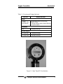
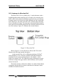
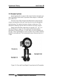
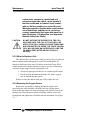
2.2.2 Anatomy of a Micro-fuel Cell
The Micro-fuel Cell is a cylinder only 1¼ inch in diameter with a
length dependent on the particular cell. It is made of an extremely inert
plastic, which can be placed confidently in practically any environment
or sample stream. It is effectively sealed, although one end is permeable
to the sample gas. The other end of the cell is a contact plate consisting
of two concentric foil rings. The rings mate with spring-loaded contacts
in the sensor block assembly and provide the electrical connection to the
rest of the analyzer. Figure 2-1 illustrates the external features.
Figure 2-1: Micro-fuel Cell
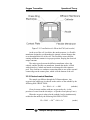
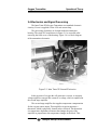
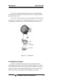
Refer to Figure 2-2, Cross Section of a Micro-fuel Cell, which
illustrates the following internal description.
At the top end of the cell is a diffusion membrane of Teflon
®
,
whose thickness is very accurately controlled. Beneath the diffusion
membrane lies the oxygen sensing element—the cathode—with a
surface area almost 4 cm
2
. The cathode has many perforations to ensure
sufficient wetting of the upper surface with electrolyte, and it is plated
with an inert metal.
The anode structure is below the cathode. It is made of lead and has
a proprietary design which is meant to maximize the amount of metal
available for chemical reaction.

Oxygen Transmitter Operational Theory
Teledyne Analytical Instruments 7
Figure 2-2: Cross Section of a Micro-fuel Cell (not to scale)
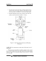
At the rear of the cell, just below the anode structure, is a flexible
membrane designed to accommodate the internal volume changes that
occur throughout the life of the cell. This flexibility assures that the
sensing membrane remains in its proper position, keeping the electrical
output constant.
The entire space between the diffusion membrane, above the
cathode, and the flexible rear membrane, beneath the anode, is filled
with electrolyte. Cathode and anode are submerged in this common
pool. They each have a conductor connecting them to one of the external
contact rings on the contact plate, which is on the bottom of the cell.
2.2.3 Electrochemical Reactions
The sample gas diffuses through the Teflon membrane. Any
oxygen in the sample gas is reduced on the surface of the cathode by the
following HALF REACTION:
O
2
+ 2H
2
O + 4e
–
→ 4OH
–
(cathode)
(Four electrons combine with one oxygen molecule—in the
presence of water from the electrolyte—to produce four hydroxyl ions.)
When the oxygen is reduced at the cathode, lead is simultaneously
oxidized at the anode by the following HALF REACTION:
Pb + 2OH
–
→ Pb
+2
+ H
2
O + 2e
–
(anode)

Operational Theory Insta Trans-XD
Teledyne Analytical Instruments 8
(Two electrons are transferred for each atom of lead that is
oxidized. Therefore it takes two of the above anode reactions to balance
one cathode reaction and transfer four electrons.)
The electrons released at the surface of the anode flow to the
cathode surface when an external electrical path is provided. The current
is proportional to the amount of oxygen reaching the cathode. It is
measured and used to determine the oxygen concentration in the gas
mixture.
The overall reaction for the fuel cell is the SUM of the half
reactions above, or:
2Pb + O
2
→ 2PbO
(These reactions will hold as long as no gaseous components
capable of oxidizing lead—such as iodine, bromine, chlorine and
fluorine—are present in the sample.)
The output of the fuel cell is limited by (1) the amount of oxygen in
the cell at the time and (2) the amount of stored anode material.
In the absence of oxygen, no current is generated.
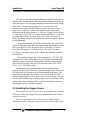
2.2.4 The Effect of Pressure
In order to state the amount of oxygen present in the sample in
parts-per-million or a percentage of the gas mixture, it is necessary that
the sample diffuse into the cell under constant pressure.
If the total pressure increases, the rate that oxygen reaches the
cathode through the diffusing membrane will also increase. The electron
transfer, and therefore the external current, will increase, even though
the oxygen concentration of the sample has not changed. It is therefore
important that the sample pressure at the fuel cell (usually vent pressure)
remain relatively constant between calibrations.
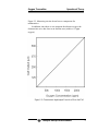
2.2.5 Calibration Characteristics
Given that the total pressure of the sample gas on the surface of the
Micro-fuel Cell input is constant, a convenient characteristic of the cell
is that the current produced in an external circuit is directly proportional
to the rate at which oxygen molecules reach the cathode, and this rate is
directly proportional to the concentration of oxygen in the gaseous
mixture. In other words it has a linear characteristic curve, as shown in
Page is loading ...
Page is loading ...
Page is loading ...
Page is loading ...
Page is loading ...
Page is loading ...
Page is loading ...
Page is loading ...
Page is loading ...
Page is loading ...
Page is loading ...
Page is loading ...
Page is loading ...
Page is loading ...
Page is loading ...
Page is loading ...
Page is loading ...
Page is loading ...
Page is loading ...
Page is loading ...
Page is loading ...
Page is loading ...
Page is loading ...
Page is loading ...
Page is loading ...
Page is loading ...
-
 1
1
-
 2
2
-
 3
3
-
 4
4
-
 5
5
-
 6
6
-
 7
7
-
 8
8
-
 9
9
-
 10
10
-
 11
11
-
 12
12
-
 13
13
-
 14
14
-
 15
15
-
 16
16
-
 17
17
-
 18
18
-
 19
19
-
 20
20
-
 21
21
-
 22
22
-
 23
23
-
 24
24
-
 25
25
-
 26
26
-
 27
27
-
 28
28
-
 29
29
-
 30
30
-
 31
31
-
 32
32
-
 33
33
-
 34
34
-
 35
35
-
 36
36
-
 37
37
-
 38
38
-
 39
39
-
 40
40
-
 41
41
-
 42
42
-
 43
43
-
 44
44
-
 45
45
-
 46
46


Teledyne Insta Trans-XD User manual
- Category
- Oxygen Equipment
- Type
- User manual
Ask a question and I''ll find the answer in the document
Finding information in a document is now easier with AI
Related papers


Other documents
-
CMA ML63m User guide
-
FlePow 8541833494 User guide
-
Quick Dam QDID224 User manual
-
-
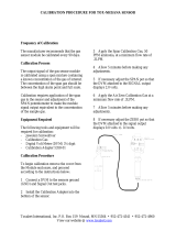 Toxalert Tox-NH3/ANA Calibration Procedures
-
iON Insta Sound User guide
-
NetSafety Electrochemical CO Detector Owner's manual
-
Micro Innovations PDOPT15W Quick Installation Manual
-
Omega TXCO-50 Owner's manual
-
 apogee INSTRUMENTS O2M-D Owner's manual

