Page is loading ...

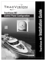
Installation Guide
TracVision
®
M7
Master Control Panel Configuration
Tapered Baseplate Version

TracVision
®
M7 Installation Guide
Tapered Baseplate Version - Master Control Panel (MCP) Configuration
1
KVH, TracVision, and the unique light-colored dome with dark contrasting baseplate are registered trademarks of KVH Industries, Inc.
All other trademarks are property of their respective companies. The information in this document is subject to change without notice.
No company shall be liable for errors contained herein. © 2013 KVH Industries, Inc., All rights reserved. 54-0941 Rev. A
These instructions explain how to install the TracVision M7 satellite TV antenna system on a
vessel. Complete instructions on how to use the system are provided in the User’s Guide.
Installation Steps
Who Should Install the System?
To ensure a safe and effective installation, KVH recommends that a KVH-authorized marine
technician install the TracVision antenna. KVH-authorized technicians have the tools and
electronics expertise necessary to install the system. To find a technician near you, visit
www.kvh.com/wheretogetservice.
Linear vs. Circular Systems
The installation process differs slightly depending on the type of LNB (low noise block) that is
installed in the antenna (linear or circular). These differences are noted throughout this manual.
Appendix B on page 30 notes the satellites available for each LNB type and geographic region.
Technical Support
If you need technical assistance, please contact KVH Technical Support:
1. Inspect Parts and Get Tools ................. 3
2. Plan the Antenna Installation .............. 4
3. Plan the Belowdecks Installation ........ 5
4. Prepare the Belowdecks Sites .............. 6
5. Prepare the Antenna Site...................... 7
6. Wire the Antenna .................................. 8
7. Mount the Antenna ............................... 9
8. Remove the Shipping Restraints ....... 11
9. Wire the Switchplate........................... 12
10. Wire the MCP and Receivers..............13
11. Connect Power ..................................... 15
12. Mount the Switchplate & MCP..........16
13. Turn On the System.............................17
14. Choose an Operating Mode................ 18
15. Select Satellites......................................19
16. Set the LNB Skew Angle.....................25
17. Run a Check Switch Test..................... 26
18. Educate the Customer .........................28
North/South America, Australia:
Phone: +1 401 847-3327
E-mail: [email protected]
Europe, Middle East, Asia:
Phone: +45 45 160 180
E-mail: [email protected]vh.dk

3
Before you begin, make sure you have
everything you need to complete the installation.
a. Unpack the box and ensure it contains
everything shown on the Kitpack Contents
List. Save the packaging for future use.
b. Carefully examine all of the supplied parts to
ensure nothing was damaged in shipment.
c. Gather all of the tools and materials listed
below. You will need these items to complete
the installation.
• Flat-head and Phillips-head screwdrivers
• Electric drill and 5/8" (16 mm), 5/32"
(4 mm), 3/32" (2.25 mm), and #29 bits
• 3.75" (95 mm) hole saw
• 9/16" and 3/4" socket wrenches
• 7/16" open-end wrench
• Torque wrench and 2 mm allen hex key
• Light hammer and center punch
• Adhesive tape and scriber or pencil
• Wire strippers and terminal lug crimper
• RG-6 or RG-11 RF coax cable(s) with
Snap-N-Seal
®
F-connectors; see Step 7a
on page 8 for quantity and type required
• Augat IT1000 connector installation tool
• Switchplate power cables (not supplied;
see Figure 2 and page 15)
• Silicone sealant, self-vulcanizing tape, or
equivalent
• Satellite TV receiver and TV (see Figure 3
for a list of validated U.S./Canadian receivers)
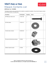
Radome
Antenna
Baseplate
Switchplate
Master Control Panel (MCP)
Figure 1: TracVision M7 System Components
Always lift the antenna by the baseplate (see
Figure 1) or hoisting eyelets (see Figure 16 on
page 9) and never by the radome.
IMPORTANT!
Figure 2: Switchplate Power Cable Guidelines
Cable Length Use Cable Gauge
< 40 ft (12 m)
14AWG (2.5mm
2
)
40-70 ft (12-21 m)
12AWG (4mm
2
)
Figure 3: KVH-Validated U.S./Canadian Receivers
Standard-Definition Models
DIRECTV DISH Network Bell TV
D12
D11
D10
311
211k/z
211
4100
3100
High-Definition (HD) Models
DIRECTV DISH Network Bell TV
HD not
supported
211
211k/z
6100
6131
Inspect Parts and Get Tools
1

4
Consider the following antenna installation
guidelines:
• Minimize blockage. The antenna requires a
clear view of the sky to receive satellite TV
(see Figure 4). The fewer obstructions, the
better the system will perform.
• Make sure the mounting surface is wide
enough to accommodate the antenna’s base
(see Figure 5). Also make sure it is flat, level
(within ±1°), strong enough to support the
antenna’s weight, and rigid enough to
withstand vibration.
• Select a location that is as close as possible to
the intersection of the vessel’s fore-and-aft
centerline and midships.
• Do not mount the antenna at the same level
as the radar because the radar’s energy might
overload the antenna. Ideally, you should
mount the antenna 4 ft (1.2 m) above the
radar, outside the beam path of the radar.
Blocked!
TracVision Antenna
Mast
Look Angle
Vessel Platform
Figure 4: Blockage from Obstruction
FWD
31.17"
(791.7 mm)
26.23"
(666.3 mm)
8.49"
(215.6 mm)
4.24"
(107.7 mm)
8.49"
(215.6 mm)
4.24"
(107.7 mm)
4 x Ø.56"
(Ø14.2 mm)
Forward
Mark
Side View
Bottom View
Ø12.00"
(Ø304.8 mm)
Figure 5: Antenna Dimensions
Be sure to follow the guidelines above.
Damage caused by an improper installation is
not covered under KVH warranty.
IMPORTANT!
Plan the Antenna Installation
2

5
Consider the following belowdecks equipment
installation guidelines.
Switchplate
• Select a switchplate mounting location in a
dry, well-ventilated area belowdecks away
from any heat sources or salt spray.
• Be sure to leave enough room at the
switchplate’s rear panel for connecting the
cables and maintaining a service loop (see
Figure 6 for switchplate dimensions).
• The supplied data cable is 100 ft (30 m) long.
Be sure to locate the switchplate close enough
to the antenna for the cable to reach, while
allowing adequate slack for a service loop.
• (Circular and Sky Mexico only) The
grounding block should be located within
95 ft (28 m) of the antenna, within 5 ft
(1.5 m) of the primary receiver, and within
25 ft (7.6 m) of a suitable vessel AC ground.
• The switchplate mounting template at the
end of this manual shows the size of the hole
required for a flush-mount installation.
MCP
• Select an MCP mounting location in a dry,
well-ventilated area belowdecks away from
any heat sources or salt spray.
• Be sure the MCP’s front panel will be easily
accessible to the user.
• Be sure to leave enough room at the MCP’s
rear panel for connecting the cables (see
Figure 7 for MCP dimensions).
• Since the supplied main control cable and RF
control cable are 25 ft (7.6 m) long, the MCP
must be located within 25 ft (7.6 m) of the
switchplate. Later, you will connect the MCP
to the switchplate using these special cables.
• The kitpack contains parts for mounting the
MCP either to a horizontal surface (using
Velcro) or to a vertical surface (using the
supplied flush mount bracket). The MCP
mounting template at the end of this manual
shows the size of the hole required for a
flush-mount installation.
Figure 6: Switchplate Dimensions
2.16"
(54.9 mm)
2.96"
(75.2 mm)
4.39"
(111.5 mm)
Front View
Top View
8.1"
(205.7 mm)
3.17"
(80.6 mm)
0.66"
(16.7 mm)
2.52"
(64.1 mm)
Figure 7: MCP Dimensions
Front View
Top View
Plan the Belowdecks Installation
3

6
Once you have identified suitable mounting sites
for the switchplate and MCP, follow these steps
to prepare the sites for installation.
Switchplate
a. Using the switchplate mounting template
provided at the end of this manual, mark and
cut out a hole in the mounting surface to
accommodate the switchplate (see Figure 8).
b. Using the same template, mark the locations
for the four switchplate mounting holes.
c. Drill a 3/32" (2.25 mm) hole at the four
mounting hole locations. Later, you will
mount the switchplate using four #6 screws.
MCP (Flush Mount only)
NOTE: Skip this step if you plan to mount the MCP
to a horizontal surface instead; proceed to page 7.
a. Attach the supplied flush mount bracket to
the MCP now, before you connect any cables.
Simply slide the bracket onto the MCP from
behind and position the front edge of the
bracket over the seam line between the front
bezel and the chassis. Secure the bracket in
place using two #6-32 screws and washers
(see Figure 9).
b. Using the MCP flush mounting template
provided at the end of this manual, mark and
cut out a hole in the mounting surface to
accommodate the flush mount bracket (see
Figure 10).
c. Using the same template, mark the locations
for the four MCP mounting holes.
d. Using a #29 drill bit, drill a 0.136" (3.45 mm)
hole at the four mounting hole locations.
Later, you will mount the MCP using four #8
screws.
3/32" ( 2.25 mm)
Mounting Hole (x4)
3.82"
(97 mm)
.32" (8 mm)
2.36"
(60 mm)
.16" (4 mm)
3.19"
(81 mm)
2.05"
(52 mm)
Panel Cutout
Figure 8: Switchplate Mounting Holes Layout
#6-32 x 1/2" Screw
and Washer (x2)
Seam Line
Figure 9: MCP Flush Mount Bracket
8.87"
(225 mm)
7.62"
(194 mm)
.63"
(16 mm)
3.08"
(78 mm)
1.83"
(46 mm)
.63"
(16 mm)
.136" ( 3.45 mm)
Mounting Hole (x4)
Figure 10: MCP Mounting Holes Layout
Prepare the Belowdecks Sites
4

7
Once you have identified a suitable antenna
mounting site, according to the guidelines
provided on page 4, follow these steps to drill the
mounting holes and cable access hole to prepare
the site for installation.
a. Unfold the antenna mounting template
(supplied in the Customer Welcome Kit) and
place it onto the mounting surface. Make sure
the “FWD” (forward) arrow points toward
the bow and is parallel to the vessel’s
centerline (see Figure 11).
NOTE: You don’t need to mount the antenna exactly
on the vessel’s centerline (the closer, the better), but
the antenna’s forward arrow must be parallel to it.
b. Using a light hammer and center punch,
mark the locations for the four mounting
holes and cable access hole on the mounting
surface in the locations indicated on the
template.
c. Drill a 5/8" (16 mm) hole at the four
mounting hole locations you marked in
Step b. Later, you will insert four 1/2"-13
bolts through these holes to secure the
antenna to the mounting surface.
d. Cut out the 3.75" (95 mm) cable access hole in
the location you marked in Step b. Smooth
the edges of the hole to protect the cables.
Later, you will route the data, power, and RF
cables through this hole and into the vessel.
e. Clean and dry the antenna mounting surface.
f. Peel off the paper backing from the supplied
foam seal to expose the adhesive. Then press
the foam seal down firmly onto the mounting
surface, ensuring the hole in the foam seal
aligns with the cable access hole in the
mounting surface (see Figure 11).
NOTE: Apply the foam seal to the vessel mounting
surface, not to the antenna’s baseplate. You will have
difficulty connecting the cables to the antenna if the
foam seal is attached to the baseplate.
8.49"
(216 mm)
Ø.63" (Ø16 mm)
Mounting Hole (x4)
8.49"
(216 mm)
Ø3.75" (Ø95 mm)
Cable Access Hole
FWD
Foam Seal
Good Bolt
Pattern
Poor Bolt
Pattern
Figure 11: Antenna Mounting Holes Layout
Prepare the Antenna Site
5

8
Follow these steps to connect the data, power,
and RF cables to the antenna.
a. First determine the number of RF coax cables
you need to connect to the antenna for your
particular installation (see Figure 12). (See
Figure 13 to determine the type of cable
required.)
NOTE: To support future configurations, you can
run all four cables
b. Route the data, power, and RF cables
belowdecks through the 3.75" (95 mm) cable
access hole. Leave an adequate service loop,
approximately 8" (20 cm) of slack, in the
cables for easy serviceability. Later, you will
connect the data and power cables to the
switchplate and the RF cable(s) to the
receiver(s).
c. Connect the data cable to the “Data”
connector on the bottom of the antenna (see
Figure 14). Hand-tighten until the cable locks
in place; do not use excessive force.
d. Connect the power cable to the “Power”
connector on the bottom of the antenna.
Hand-tighten until the cable locks in place;
do not use excessive force.
e. Connect the RF coax cable(s) to the antenna.
If you need to connect just one RF cable,
connect the cable to the “RF1” connector on
the bottom of the antenna. Hand-tighten,
then tighten with a 7/16" wrench for 1/4 turn
to ensure an electrical connection. Connect
any additional RF coax cables to the
antenna’s RF2, RF3, and RF4 connectors, in
that order.
TIP: If you connect two or more RF cables, label both
ends of each cable to match the connector. This will
make it easier to identify the cables later.
f. Seal the RF cable connections with silicone
sealant, self-vulcanizing tape, or equivalent.
Figure 12: Number of RF Coax Cables to Connect to Antenna
* Multiswitch required for additional receivers.
Connecting to: # RF Cables
System with Circular Dual LNB
1 receiver 1
2 receivers 2
3 or more receivers 2*
System with Linear Dual LNB
1 receiver 1
2 receivers 2
System with Linear Quad LNB
1 receiver 1
2 receivers 2
3 receivers 3
4 receivers 4
5 or more receivers 4*
Figure 13: RF Cable Guidelines
Cable Length Use Cable Type
<= 75 ft (23 m) RG-6
75-100 ft (23-30.5 m) RG-11
Figure 14: Connectors on Bottom of Antenna
RF3
Power
RF1
RF4
Data
RF2
Wire the Antenna
6

9
Follow the steps below to mount the antenna.
a. Remove the six #10-32 Phillips screws
securing the radome to the baseplate (see
Figure 15). Carefully lift the radome straight
up until clear of the antenna assembly and set
it aside in a safe place. If you keep the radome
topside, secure it with a lanyard to prevent it
from falling overboard. Also, do not place the
radome on a hot steel deck – the heat may
warp the radome.
b. Keeping shipping restraints in place,
transport the antenna to the mounting
location.
NOTE: The two hoisting eyelets on the antenna frame
may be used to lift the antenna, if necessary (see
Figure 16). After they have been used once, make sure
they are undamaged and free of cracks before using
them again.
c. Place the antenna baseplate over the holes
drilled in the mounting surface.
d. Ensure the forward arrow inside the
baseplate points toward the bow and is
parallel to the vessel’s centerline (see
Figure 17).
CAUTION
Observe the safety warnings printed on the
tube of Loctite
®
anti-seize lubricant:
“Contains mineral oil, calcium hydroxide,
and copper. May cause skin, eye, and
respiratory irritation. Wear eye protection
and gloves. First aid: In case of eye or skin
contact, flush with water. Obtain medical
attention for any eye or internal contact.”
#10-32 Screw (x6)
Figure 15: Removing the Radome
Hoisting Eyelets (x2)
Figure 16: Hoisting Eyelets
FORWARD
Figure 17: Forward Arrow in Antenna Baseplate
Mount the Antenna
7

10
e. Apply a thin layer of the supplied anti-seize
lubricant to the threads of the four 1/2"-13
mounting bolts (see Figure 18).
f. Using a 3/4" socket, secure the antenna to the
mounting surface using four 1/2"-13 bolts,
lock washers, and flat washers from below
(see Figure 18). Tighten all four bolts until the
four rubber feet on the baseplate are
bottomed against the mounting surface and
the foam seal is fully compressed. KVH
recommends that you tighten the bolts to
between 34 and 40 ft-lbs (46.1 and 54.2 N-m)
of torque.
Be sure your 1/2"-13 mounting bolts extend
between 1.5" (38 mm) and 1.75" (44 mm) into
the baseplate to ensure sufficient thread
engagement.
IMPORTANT!
1/2"-13 Bolt (x4)
IMPORTANT!
Apply anti-seize
to threads
Flat Washer (x4)
Mounting Surface
Baseplate
Foam Seal
1.75" max
Lock Washer (x4)
Figure 18: Mounting the Antena (Side View)
Continued Mount the Antenna
7

11
Follow the steps below to remove the shipping
restraints from the antenna.
a. Remove the foam block that is wedged
beneath the antenna’s reflector (see
Figure 19). Save this restraint for future use;
the customer will need to reinstall it if he/she
needs to relocate or reship the antenna.
b. Using a 9/16" nut driver or wrench, remove
the two 3/8" bolts, washers, and lock nuts
securing the two shipping restraint brackets
to the frame (see Figure 20).
NOTE: Be sure to keep the shipping restraint brackets
for future use.
c. In place of the brackets, place a 3/8" flat
washer (supplied in the kitpack) on each of
the two 3/8" bolts that you just removed.
Then reinstall the bolts and secure them in
place with the washers and lock nuts you
removed earlier.
TIP: If you are installing a linear system, keep the
radome off for now. You will need to adjust the skew
angle of the antenna’s LNB.
d. Reinstall the radome onto the antenna. Secure
in place with the six #10-32 screws you
removed earlier (see Figure 15 on page 9).
e. Install a protective plastic cap (supplied in
the kitpack) over each radome screw.
Shipping
Restraint
Figure 19: Foam Block Shipping Restraint
3/8" Bolt (x2)
Lock Nut (x2)
Washer (x2)
Bracket (x2)
Replace with Washer
(supplied in kitpack)
Figure 20: Shipping Restraint Bracket Removal
Remove the Shipping Restraints
8

12
Follow these steps to connect the switchplate to
the antenna.
a. First dress the data and power cables from
the antenna. Strip back the insulation of each
wire approximately 1/4" (6 mm) and gently
twist each wire to ensure a good electrical
connection.
b. Connect the data cable from the antenna to
the terminal board on the back of the
switchplate (see Figure 21). Be sure to match
the wire colors with the terminal board label.
Tighten the terminal screws to secure all
wires in place.
c. Connect the power cable from the antenna to
the switchplate’s power output terminals (see
Figure 22). Later, you will also connect a
power cable from these terminals to the MCP.
Figure 21: Switchplate Wiring - Antenna Data Cable
Brown/White
White/Brown
Orange/White
White/Orange
Gray/White
White/Gray
Antenna
Data Cable
Body/Stripe
The diagram refers to wires by body color/
stripe color. For example, “Brown/White”
means the brown wire with the white stripe.
IMPORTANT!
Do not connect the data cable’s drain wire
(shield) to anything. You can simply snip it
from the cable.
IMPORTANT!
Figure 22: Switchplate Wiring - Antenna Power Cable
+12 VDC (Red)
Ground (Black)
Antenna Power Cable
+
–
Wire the Switchplate
9

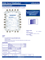
13
If you are installing a circular system, or a linear
system for Sky Mexico, follow these steps to
connect the switchplate to the MCP and the
antenna to the receiver(s).
a. Connect the main control cable (DB9-male to
DB9-male) from the “Maintenance” port on
the front or back of the switchplate to the
“Antenna Unit” connector on the MCP (see
Figure 23).
NOTE: The switchplate’s two DB9 connectors access
the same port. Connecting to one disables the other.
b. Connect the RF control cable (RJ22 to
DB9-female) from the RJ22 jack on the back of
the switchplate to the “RF Port” connector on
the MCP.
c. Connect the RF1 cable from the antenna to
the grounding block, as shown in Figure 23.
Label this grounding block connector “RF1.”
d. If you are connecting multiple receivers,
connect the RF2 cable from the antenna to the
grounding block. Label this connector “RF2.”
e. Attach the supplied ground wire to either
ground screw on the grounding block.
Connect the other end of the wire to a
suitable vessel AC ground.
f. Using the two supplied #6 screws, mount the
grounding block inside the vessel.
g. Connect the supplied 5-ft RF cable from the
“RF1” connector on the grounding block to
the “Satellite In” connector on the primary
receiver.
h. If you are connecting two receivers, connect
an RF cable from the “RF2” connector on the
grounding block to the “Satellite In”
connector on the secondary receiver.
i. Connect the receiver(s) to the customer’s
television(s). Follow the instructions in the
receiver’s manual
SATELLITE IN
OUT TO TV
TV ANT/CABLE IN
AUDIO VIDEO S-VIDEO PHONE JACK
RL
SATELLITE IN
OUT TO TV
TV ANT/CABLE IN
AUDI O VID EO S-VIDEO PHONE JACK
RL
Satellite In
HDTV
CONTROL
ANTENNA UNIT RF PORT TONE
DETECT
FUSE POWER IN
+ / –
MCP
Switchplate
Antenna
Secondary Receiver - Optional
RF1
RF2
Primary Receiver
This receiver controls satellite selection
Satellite In
Antenna Unit RF Port
RJ22
Terminal Strip
Power
OR
DB9
RF1RF2
(Optional)
Grounding
Block
Vessel
AC Ground
Ground Wire
#6 Mounting
Screw (x2)
Main Control RF Control
Maintenance
RF2 (Optional)
RF1
Power
Data
Figure 23: MCP and Receiver Wiring
If you wish to connect three or more receivers
to the antenna, see Appendix A on page 28
(circular) or page 29 (Sky Mexico).
IMPORTANT!
Wire the MCP and Receivers
10
Circular and Sky Mexico

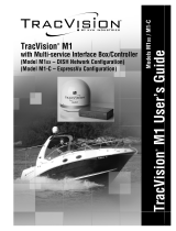
14
If you are installing a linear system (with the
exception of Sky Mexico), follow these steps to
connect the switchplate to the MCP and the
antenna to the receiver(s).
a. Connect the main control cable (DB9-male to
DB9-male) from the “Maintenance” port on
the front or back of the switchplate to the
“Antenna Unit” connector on the MCP (see
Figure 24).
b. Connect the RF control cable (RJ22 to
DB9-female) from the RJ22 jack on the back of
the switchplate to the “RF Port” connector on
the MCP.
c. Connect the RF1 cable from the antenna to
the “Satellite In” connector on the primary
receiver. The primary receiver controls
satellite selection. The switchplate’s two DB9
connectors access the same port. Connecting
to one disables the other.
NOTE: Any additional receiver(s) will be able to
select channels carried on the satellite that is currently
selected by the primary receiver.
d. If you have a second receiver, connect the
RF2 cable from the antenna to the “Satellite
In” connector on the second receiver.
e. If the system is equipped with a quad LNB,
connect the RF3 and RF4 cables from the
antenna to the “Satellite In” connectors on the
third and fourth receivers, if applicable.
NOTE: If you need to connect more than four
receivers, install an active multiswitch that generates
a 22 KHz tone (such as Eagle Aspen 501481 - KVH
part no.19-0573). Connect the multiswitch in
accordance with the manufacturer’s instructions.
f. Connect the receiver(s) to the television(s).
Follow the steps in the receiver’s manual.
RJ22
Terminal Strip
DB9
SATELLITE IN
OUT TO TV
TV ANT/CABLE IN
AUDIO VIDEO S-VIDEO PHONE JACK
RL
SATELLITE IN
OUT TO TV
TV ANT/CABLE IN
AUDIO VIDEO S-VIDEO PHONE JACK
RL
Satellite In
Receiver #2 - Optional
Receiver #1 (Primary)
This receiver controls satellite selection
Satellite In
HDTV
CONTROL
ANTENNA UNIT RF PORT TONE
DETECT
FUSE POWER IN
+ / –
MCP
Switchplate
Antenna
RF1
RF2
Antenna Unit RF Port
RF2 (Optional)
RF1
Power
Data
OR
SATELLITE IN
OUT TO TV
TV ANT/CABLE IN
AUDIO VIDEO S-VIDEO PHONE JACK
RL
Satellite In
Receiver #3 - Optional
RF3
SATELLITE IN
OUT TO TV
TV ANT/CABLE IN
AUDIO VIDEO S-VIDEO PHONE JACK
RL
Satellite In
Receiver #4 - Optional
RF4
RF3 (Optional)
Quad LNB Only
RF4 (Optional)
Power
Maintenance
Main Control
RF Control
Figure 24: MCP and Receiver Wiring
Be sure all receivers are grounded. If the
receiver has a 2-prong power plug, run a
ground wire from the receiver’s chassis to a
suitable ground point. If a potential exists
between AC and DC grounds, connect the
wire to the switchplate’s DC return instead.
IMPORTANT!
Continued Wire the MCP and Receivers
10
Linear Systems

15
Follow these steps to connect power. The
switchplate supplies power to both the antenna
and the MCP.
a. Before you begin, disconnect vessel power.
b. Route a set of power wires from the
switchplate’s power output terminals to the
MCP (for cable specifications, see Figure 2 on
page 3). Connect the wires to the plastic
power plug supplied in the kitpack (see
Figure 25).
NOTE: You should now have two wires connected to
each power output terminal on the switchplate: one set
of wires to power the antenna and one set to power the
MCP.
c. Tighten the terminal screws on the
switchplate to secure all wires in place.
d. Plug the MCP power plug into the “Power
In” jack on the MCP (see Figure 26). Secure in
place with the retaining screws.
e. Connect a power cable to 12 VDC (4 amps
continuous) vessel power (for cable
specifications, see Figure 2 on page 3).
Route
the other end to the switchplate.
f. Detach the two terminal connectors from the
back of the switchplate and crimp them onto
the power cable’s wires.
g. Connect the power cable wires to the power
(+) and ground (-) input terminals on the
switchplate (see Figure 27).
CAUTION
For your own safety, disconnect vessel power
and make sure the circuit is dead before you
connect any power wires.
Figure 25: MCP Power Plug
Terminal Screw (x2)
GroundPower
Retaining Screw (x2)
Figure 26: MCP Power Wiring
HDTV
CONTROL
ANTENNA UNIT RF PORT TONE
DETECT
FUSE POWER IN
+ / –
Switchplate-to-MCP
Power Cable
MCP
+
–
+
–
Power In
Power supplied to the antenna must not fall
below 12 VDC or exceed 16 VDC.
IMPORTANT!
Figure 27: Switchplate Wiring - Vessel Power Cable
+
–
+12 VDC
Ground
Vessel Power
Connect Power
11

16
In Step 4, you prepared the mounting sites for the
switchplate and MCP. Now follow these steps to
mount them.
Switchplate
NOTE: As an alternative, the switchplate includes
two additional mounting holes for installing within
an electrical panel. If you chose this option, simply use
two of the #6 screws to mount the switchplate to the
panel.
a. Align the four mounting holes in the
switchplate with the holes in the mounting
surface (see Figure 28).
b. Mount the switchplate to the mounting
surface using four #6 screws.
c. Gently snap the front cover onto the
switchplate to conceal the mounting screws.
MCP - Velcro Mount Option
a. Clean and dry the bottom of the MCP and the
mounting surface (use a mild detergent).
b. Peel the backing from the two supplied
Velcro fabric squares and stick them to the
bottom of the MCP (see Figure 29).
c. Position the two Velcro hook disks onto the
mounting surface. Drill screw holes for the
disks and secure in place with #4-24 screws.
d. Press the MCP firmly into place so that the
fabric’s loop material engages the hook disks.
MCP- Flush Mount Option
a. Make sure the flush mount bracket is
attached to the MCP. If it is not attached,
disconnect all of the cables from the MCP,
attach the bracket as explained in Step 4 on
page 6, then reconnect the cables.
b. Insert the MCP and bracket assembly into the
mounting hole and secure in place with four
#8 screws and washers (see Figure 30).
5/32" ( 4 mm)
Mounting Hole (x4)
#6 Screw (x4)
Fron
t
C
over
Switchpla
t
e
Mo
u
nti
ng Surfac
e
Figure 28: Mounting the Switchplate
Fabric Strip (x2)
Hook Disk (x2)
#4-24 Screw (x2)
Figure 29: Velcro Mounting the MCP to a Horizontal Surface
#8 Screws and
Washers (x4)
Figure 30: Flush Mounting the MCP to a Vertical Surface
Mount the Switchplate & MCP
12

17
Follow these steps to turn on the TracVision
system.
a. Ensure the antenna has a clear, unobstructed
view of the sky so it can receive satellite
signals.
b. Apply power to the satellite TV receiver(s)
and TV(s).
c. Set the switchplate’s power switch to the
“on” position to apply power to the
TracVision system (see Figure 31).
d. Wait one minute for system startup. When
the MCP display shows “Set up satellite(s),”
proceed to the next step.
OFF
ON
Figure 31: Switchplate Power Switch
Turn On the System
13

18
If you are installing a circular system, choose the
appropriate operating mode for your customer’s
satellite TV service provider and satellite
preferences (see Figure 32). You will select this
mode in the next step.
DIRECTV
Dual-Sat:
Select this mode if you wish to receive
programming from the 101 and 119 satellites for
DIRECTV service.
Tri-Sat or Tri-Sat Pairs:
Do not use either of these modes for a new
installation. The Tri-Sat Auto mode supports the
Tri-Sat AutoSwitch; the Tri-Sat Pairs mode
supports the HDTV Converter. These HDTV
devices are no longer available.
DISH Network
DISH 1000/61 or DISH 1000/129:
Select one of these modes for DISH Network’s
three-satellite service (DISH 1000). Use the map
in Figure 33 to help determine the appropriate
DISH 1000 mode for your geographic area. Check
with DISH Network for local channels
availability.
DISH 500:
Select this mode if you wish to receive
programming from the 119 and 110 satellites for
DISH 500 service.
Bell TV (formerly ExpressVu)
Select the Bell TV service to receive Bell TV
programming from the 91 and 82 satellites.
Custom
If none of the above modes meets your
customer’s needs, you may select any two
satellites from the antenna’s built-in library using
the Custom service mode.
Figure 32: Satellites Tracked in Each Operating Mode
DIRECTV
DISH Network
* Optional Master Receiver Selector (KVH part #72-0412)
required for automatic satellite switching; multiswitch
(KVH part #72-0310) required for manual switching; see
Appendix A on page 28.
Bell TV
Mode Satellites Tracked
Dual-Sat 101 and 119
Tri-Sat or Tri-Sat
Pairs (Not used)
101, 110, and 119
Mode Satellites Tracked
DISH 1000/61 119, 110, and 61
DISH 1000/129* 119, 110, and 129
DISH 500 119 and 110
Mode Satellites Tracked
Bell TV 91 and 82
= DISH 61 Satellite Recommended
= DISH 129 Satellite Recommended
Figure 33: Recommended Areas for DISH 1000 Satellites
Choose an Operating Mode
14
Circular Systems - Only

19
Follow these steps and refer to the flowchart in
Figure 34 to set up the system for a DIRECTV
mode (see Step 14 on page 17 for a description of
each mode).
a. At “Set up satellite(s),” press the YES button
on the MCP’s front panel.
b. At “Circular or Linear?,” press CIR.
c. At “Service=DIRECTV,” press YES.
d. At “Mode=Dual-Sat?,” press NEXT until the
display shows the desired DIRECTV mode.
Then press YES.
e. At “Set Sat Switch Type,” press AUTO for
automatic satellite switching or MANUAL
for manual switching. Manual switching is
only required if a multiswitch is installed.
f. At “Set Lat/Long?,” press YES.
TIP: You can determine your approximate latitude
and longitude in North America from the position
grids provided in Appendix C on page 31.
g. At “Latitude,” use the - and + buttons to set
each digit of the vessel’s latitude. Press Enter
to accept each digit.
h. At “Longitude,” set the vessel’s longitude.
Set up satellite(s)?
Yes No
Service=DIRECTV?
Yes Next Cancel
Mode=Dual-Sat?
Yes Next Cancel
Mode=Tri-Sat?
Yes Next Cancel
Mode=Tri-Sat Pairs?
Yes Next Cancel
Press NEXT until
desired mode displays;
then press YES
Circular or Linear?
Cir Lin Cancel
Set Sat Switch Type
Auto Manual Cancel
Longitude: ###E
- Enter +
Set Lat/Long?
Yes Next Cancel
Latitude: ##N
- Enter +
Use +/- to set
vessel latitude
Use +/- to set
vessel longitude
Latitude: ##N
Longitude: ###E
Displays satellites
installed for the
selected mode
Installing DTV sats
Restarting antenna
Figure 34: DIRECTV Satellite Selection Menus on MCP
Select Satellites
15
Circular Systems - DIRECTV

20
Follow these steps and refer to the flowchart in
Figure 35 to set up the system for a DISH
Network mode (see Step 14 on page 17 for a
description of each mode).
a. At “Set up satellite(s),” press the YES button
on the MCP’s front panel.
b. At “Circular or Linear?,” press CIR.
c. At “Service=DIRECTV,” press NEXT until
the display shows “Service=DISH.” Then
press YES.
d. At “Mode=DISH 1000/61?,” press NEXT
until the display shows the desired DISH
mode. Then press YES.
e. At “Set Sat Switch Type,” press AUTO for
automatic satellite switching or MANUAL
for manual switching. Manual switching is
only required if a multiswitch is installed.
f. At “Set Lat/Long?,” press YES.
TIP: You can determine your approximate latitude
and longitude in North America from the position
grids provided in Appendix C on page 31.
g. At “Latitude,” use the - and + buttons to set
each digit of the vessel’s latitude. Press Enter
to accept each digit.
h. At “Longitude,” set the vessel’s longitude.
Service=DIRECTV?
Yes Next Cancel
Mode=DISH 1000/61?
Yes Next Cancel
Mode=DISH 1000/129?
Yes Next Cancel
Mode=DISH 500?
Yes Next Cancel
Press NEXT until
desired mode displays;
then press YES
Service=DISH?
Yes Next Cancel
Set up satellite(s)?
Yes No
Circular or Linear?
Cir Lin Cancel
Longitude: ###E
- Enter +
Set Lat/Long?
Yes Next Cancel
Latitude: ##N
- Enter +
Use +/- to set
vessel latitude
Use +/- to set
vessel longitude
Latitude: ##N
Longitude: ###E
Set Sat Switch Type
Auto Manual Cancel
Displays satellites
installed for the
selected mode
Installing DISH sats
Restarting antenna
Figure 35: DISH Satellite Selection Menus on MCP
Select Satellites
15
Circular Systems - DISH
/