Gigabyte GA-7VAXP Ultra User manual
- Category
- Motherboards
- Type
- User manual
This manual is also suitable for

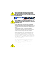
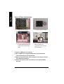
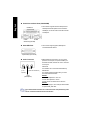
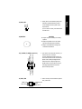
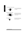
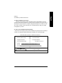
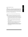
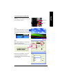
When you installing AGP card, please make sure the following
notice is fully understood and practiced. If your AGP card has
"AGP 4X/8X(1.5V) notch"(show below), please make sure your AGP
card is AGP 4X/8X(1.5V).
Caution: AGP 2X(3.3V) card is not supported by VIA
®
KT400. You
might experience system unable to boot up normally. Please insert
an AGP 4X/8X(1.5V) card
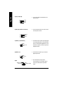
Example 1: Diamond Vipper V770 golden finger is compatible with
2X/4X mode AGP slot. It can be switched between AGP 2X(3.3V) or 4X
(1.5V) mode by adjusting the jumper. The factory default for this card is
2X(3.3V).
The GA-7VAX / GA-7VAX1394 / GA-7VAXP / GA-7VAXP Ultra
(or any AGP 4X only) motherboards might not function properly, if you
install this card without switching the jumper to 4X(1.5) mode in it.
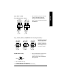
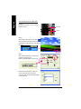
Example 2: Some ATi Rage 128 Pro graphics cards made by “Power
Color”, the graphics card manufacturer & some SiS 305 cards, their
golden finger is compatible with 2X(3.3V)/4X(1.5V) mode AGP slot, but
they support 2X(3.3V) only. The GA-7VAX / GA-7VAX1394 / GA-7VAXP
/ GA-7VAXP Ultra (or any AGP 4X only) motherboards might not function
properly, If you install this card in it.
Note : Although Gigabyte's AG32S(G) graphics card is based on
ATi Rage 128 Pro chip, the design of AG32S(G) is compliance
with AGP 4X(1.5V) specification. Therefore, AG32S (G)will work
fine with VIA
®
KT400 based motherboards.
Before you install PCI cards, please remove the Dual BIOS
label from PCI slots if there is one.
AGP 4X/8X notch

M The author assumes no responsibility for any errors or
omissions that may appear in this document nor does the
author make a commitment to update the information contained
herein.
M Third-party brands and names are the property of their
respective owners.
M Please do not remove any labels on motherboard, thismay void
the warranty of this motherboard.
M Due to rapid change in technology, some of the specifications
might be out of date before publication of this booklet.

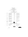
Declaration of Conformity
We, Manufacturer/Importer
(full address)
G.B.T. Technology Träding GMbH
Ausschlager Weg 41, 1F, 20537 Hamburg, Germany
declare that the product
( description of the apparatus, sy stem, installation to w hich it refers)
Mother Board
GA-7VAX / GA-7VAX1394 / GA-7VAXP / GA-7VAXP Ultra
is in conformity with
(reference to the specification under which conformity is declared)
in accordance with 89/336 EEC-EMC Directive
o EN 55011 Limits and methods of measurement
of radio disturbance characteristics of
industrial,scientific and medical (ISM
high frequency equipment
o EN 61000-3-2*
T EN 60555-2
Disturbances in supply systems cause
by household appliances and similar
electrical equipment “Harmonics”
o EN 55013
Limits and methods of measurement
of radio disturbance characteristics of
broadcast receivers and associated
equipment
o EN 61000-3-3* Disturbances in supply systems cause
by household appliances and similar
electrical equipment “Voltage fluctuations”
o EN 55014 Limits and methods of measurement
of radio disturbance characteristics of
household electrical appliances,
portable tools and similar electrical
apparatus
T EN 50081-1
Generic emission standard Part 1:
Residual commercial and light industry
T EN 50082-1
Generic immunity standard Part 1:
Residual commercial and light industry
o EN 55015 Limits and methods of measurement
of radio disturbance characteristics of
fluorescent lamps and luminaries
Generic emission standard Part 2:
Industrial environment
o EN 55081-2
Immunity from radio interference of
broadcast receivers and associated
equipment
Generic emission standard Part 2:
Industrial environment
o EN 55082-2
T EN 55022 Limits and methods of measurement
of radio disturbance characteristics of
information technology equipment
lmmunity requirements for household
appliances tools and similar apparatus
o ENV 55104
Cabled distribution systems; Equipment
for receiving and/or distribution from
sound and television signals
EMC requirements for uninterruptible
power systems (UPS)
o EN50091-2
o EN 55020
o DIN VDE 0855
o part 10
o part 12
(EC conformity marking)
T CE marking
The manufacturer also declares the conformity of above mentioned product
with the actual requir ed safety standards in accordance with LVD 73/23 EEC
Safety requirements for mains operated
electronic and related apparatus for
household and similar general use
o EN 60950
o EN 60065
Safety of household and similar
electrical appliances
o EN 60335
Manufacturer/Importer
Signature:
Name:
Date : December 27, 2002
T EN 60555-3
Timmy Huang
o EN 50091-1
Timmy Huang
Safety for information technology equipment
including electrical bussiness equipment
General and Safety requirments for
uninterruptible power systems (UPS)

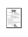
FCC Part 15, Subpart B, Section 15.107(a) and Section 15.109
(a),Class B Digital Device
DECLARATION OF CONFORMITY
Per FCC Part 2 Section 2.1077(a)
Responsible PartName:
Address:
Phone/Fax No:
hereby declares that the product
Product Name:
Conforms to the following specifications:
This device complies with part 15 of the FCC Rules. Operation is
subject to the following two conditions: (1) This device may not
cause harmful and (2) this device must accept any inference received,
including that may cause undesired operation.
Representative Person’s Name:
Signature:
Eric Lu
Supplementary Information:
Model Number:
17358 Railroad Street
City of Industry, CA 91748
G.B.T. INC. (U.S.A.)
(818) 854-9338/ (818) 854-9339
Motherboard
GA-7VAX / GA-7VAX1394
GA-7VAXP/GA-7VAXP Ultra
Date:
ERIC LU
December 27 ,2002

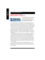
GIGABYTE obtained of the event to validate the
performance of ATi and Nvidia based graphics cards
(AGP 8X) with VIA Chipset based motherboar ds
running Microsoft operating systems. Certificates of
Validation will be supplied by VIA, ATi and nVIDIA
for GA-7VAXP Ultra; GA-7VAXP; GA-7VAX1394;
GA-7VAX and GA-7VA that successfully passed in
the AGP 8X standard validation


USER'S MANUAL
KT400 Series
AMD Socket A Processor Motherboard
AMD Athlon
™
/ Athlon
™
XP / Duron
™
Socket A Processor Motherboard
Rev. 1202
12ME-7VAXPU-1202

- 2 -KT400 Series Motherboard
English
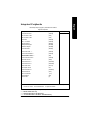
Table of Content
Item Checklist ..................................................................................... 4
WARNING! .......................................................................................... 4
Chapter 1 Introduction ......................................................................... 5
Features Summary ......................................................................................... 5
KT400 Series Motherboard Layout ............................................................... 8
Chapter 2 Hardware Installation Process .............................................. 9
Step 1: Install the Central Processing Unit (CPU) ...................................... 10
Step1-1: CPU Speed Setup ....................................................................................... 10
Step1-2: CPU Installation .......................................................................................... 11
Step1-3:CPU Heat Sink Installation ........................................................................... 12
Step 2: Install memory modules .................................................................. 13
Step 3: Install expansion cards .................................................................... 14
Step 4: Connect ribbon cables, cabinet wires, and power supply ............ 15
Step4-1 : I/O Back Panel Introduction ....................................................................... 15
Step4-2 : Connectors Introduction ............................................................................. 17
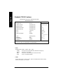
Chapter 3 BIOS Setup ....................................................................... 25
The Main Menu (For example: BIOS Ver. : F8) ......................................... 26
Standard CMOS Features ........................................................................... 28
Advanced BIOS Features ............................................................................. 31
Integrated Peripherals ................................................................................. 33
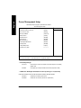
Power Management Setup .......................................................................... 38
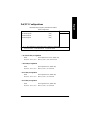
PnP/PCI Configurations ................................................................................ 41
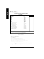
PC Health Status ........................................................................................... 42

Table of Content
English
- 3 -
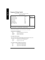
Frequency/Voltage Control ........................................................................... 44
Top Performance .......................................................................................... 47
Load Fail-Safe Defaults ................................................................................ 48
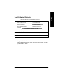
Load Optimized Defaults .............................................................................. 49
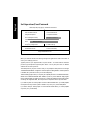
Set Supervisor/User Password..................................................................... 50
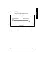
Save & Exit Setup .......................................................................................... 51
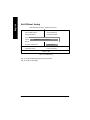
Exit Without Saving ....................................................................................... 52
Chapter 4 Technical Reference .......................................................... 55
Block Diagram .............................................................................................. 55
Dual BIOS / Q-Flash Introduction ................................................................ 67
@ BIOS Introduction ..................................................................................... 76
Easy Tune
TM
4 Introduction .......................................................................... 77
2-/4-/6-Channel Audio Function Introduction ............................................. 78
Chapter 5 Appendix .......................................................................... 85

- 4 -KT400 Series Motherboard
English
þ The KT400 Series motherboard þ RAID Manual **
þ IDE cable x 1/ Floppy cable x 1 þ 4 Port USB Cable x 1
þ IDE cable x 2 ** þ Audio combo Kit x1 **
þ CD for motherboard driver & utility þ IEEE 1394 Cable x1 ***
þ KT400 Series user’s manual o SPD Kit x1
þ I/O Shield þ Quick PC Installation Guide
þ Motherboard Settings Label þ SATA RAID Manual *
þ SATA cable x 2 * o GC-SATA Card * (Optional)
(Manual ; SATA cable x1 ; Power cable x 1)
Item Checklist
Computer motherboards and expansion cards contain very delicate Integrated Circuit (IC) chips. To
protect them against damage from static electricity, you should follow some precautions whenever you
work on your computer.
1. Unplug your computer when working on the inside.
2. Use a grounded wrist strap before handling computer components. If you do not have
one, touch both of your hands to a safely grounded object or to a metal object, such as
the power supply case.
3. Hold components by the edges and try not touch the IC chips, leads or connectors, or
other components.
4. Place components on a grounded antistatic pad or on the bag that came with the
components whenever the components are separated from the system.
5. Ensure that the ATX power supply is switched off before you plug in or remove the ATX
power connector on the motherboard.
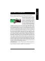
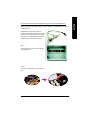
If the motherboard has mounting holes, but they don’t line up with the holes on the base and there are
no slots to attach the spacers, do not become alarmed you can still attach the spacers to the mounting
holes. Just cut the bottom portion of the spacers (the spacer may be a little hard to cut off, so be careful
of your hands). In this way you can still attach the motherboard to the base without worrying about short
circuits. Sometimes you may need to use the plastic springs to isolate the screw from the motherboard
PCB surface, because the circuit wire may be near by the hole. Be careful, don’t let the screw contact
any printed circuit write or parts on the PCB that are near the fixing hole, otherwise it may damage the
board or cause board malfunctioning.
Installing the motherboard to the chassis…
WARNING!
" * " FOR GA-7VAXP Ultra Only.
" ** " FOR GA-7VAXP Ultra / GA-7VAXP Only.
" *** " For GA-7VAXP Ultra / GA-7VAXP / GA-7VAX1394 Only.

Introduction
English
- 5 -
Form Factor — 30.5cm x 24.3cm ATX size form factor, 4 layers PCB.
Motherboard — KT400 Series:
GA-7VAX / GA-7VAX1394 / GA-7VAXP / GA-7VAXP Ultra
CPU — Socket A processor
AMD Athlon
TM
/Athlon
TM
XP/ Duron
TM
(K7)
128K L1 & 256K/64K L2 cache on die
200/266/333
<Note 1>
MHz FSB and DDR bus speeds
— Supports 1.4GHz and faster
Chipset — VIA KT400 Memory/AGP/PCI Controller (PAC)
— VIA VT8235 Integrated Peripheral Controller (PSIPC)
Memory — 3 184-pin DDR sockets
— Supports DDR DRAM PC1600/PC2100/PC2700/PC3200
<Note 2>
— Supports up to 3.0GB DDR (Max)
— Supports only 2.5V DDR DIMM
I/O Control — IT8705
Slots — 1 AGP slot supports 8X/4X/2X mode(1.5V) & AGP 3.0 Compliant
— 5 PCI slots supports 33MHz & PCI 2.2 compliant
On-Board IDE — 2 IDE controllers provides IDE HDD/CD-ROM (IDE1, IDE2) with
PIO, Bus Master (Ultra DMA33/ATA66/ATA100/ATA133)
operation modes.
— IDE3 and IDE4 Compatible with RAID,Ultra ATA133/100, EIDE **
On-Board Peripherals — 1 Floppy port supports 2 FDD with 360K, 720K,1.2M, 1.44M
and 2.88M bytes.
— 1 Parallel port supports Normal/EPP/ECP mode
— 2 Serial port (COMA & COMB)
— 6 x USB 2.0/1.1 (4 by cable)
— 3 x IEEE1394 by cable ***
— 1 IrDA connector for IR
— 1 Smart Card Reader connector for SCR
Hardware Monitor — CPU/System Fan Revolution detect
— CPU/System temperature detect
— System Voltage Detect
— Thermal shutdown function
Chapter 1 Introduction
Features Summary
to be continued......
<Note 1> FSB333 MHz only support DDR333 DIMM module.
<Note 2> PC3200 only support by Micro, Samsung, Apacer DDR module as we verified, more detail
pls refer to P.99
" *** " For GA-7VAXP Ultra / GA-7VAXP / GA-7VAX1394 Only.

- 6 -KT400 Series Motherboard
English
On-Board Sound — Realtek ALC650 CODEC
— Line Out / 2 front speaker
— Line In / 2 rear speaker(by s/w switch)
— Mic In / center& subwoofer(by s/w switch)
— SPDIF Out /SPDIF In
— CD In / AUX In / Game port
On-Board USB 2.0 — Built in VIA VT8235 Chipset
On-Board RAID ** — Onbard Promise PDC20276
— Supports data striping (RAID 0) or mirroring (RAID 1)
— Supports concurrent dual IDE controller operation
— Supports IDE bus master operation
— Displays status and error checking messages during boot-up
— Mirroring supports automatic background rebuilds
— Features LBA and Extended Interrupt 13 drive translation in
controller onboard BIOS
On-Board SATA RAID * — Onboard Silicon Image Sil3112A
— Supports Disk striping (RAID0) or DISK Mirroring (RAID1)
— Supports UDMA up to 150 MB/sec
— AIL UDMA and PIO Modes
— Up to 2 SATA Device
— ACPI and ATA/ATAPI6
On-Board LAN — RealTek RTL8100BL
On-Board IEEE1394 *** — VT6306
PS/2 Connector — PS/2 Keyboard interface and PS/2 Mouse interace
BIOS — Licensed Award BIOS, 2M bit flash ROM
— Supports Dual BIOS /Q-Flash
Additional Features — PS/2 Keyboard power on by password,PS/2 Mouse power on
— External Modem wake up
— STR(Suspend-To-RAM)
— Wake on LAN (WOL)
— AC Recovery
— Poly fuse for keyboard over-current protection
— USB KB/Mouse wake up from S3
— Supports @BIOS
— Supports EasyTune 4
Overclocking — Over Voltage (DDR/AGP/CPU) by BIOS
— Over Clock (DDR/AGP/CPU/PCI) by BIOS
" * " FOR GA-7VAXP Ultra Only.
" ** " FOR GA-7VAXP Ultra / GA-7VAXP Only.
" *** " For GA-7VAXP Ultra / GA-7VAXP / GA-7VAX1394 Only.

Introduction
English
- 7 -
Please set the CPU host frequency in accordance with your processor’s specifications.
We don’t recommend you to set the system bus frequency over the CPU’s specification
because these specific bus frequencies are not the standard specifications for CPU,
chipset and most of the peripherals. Whether your system can run under these specific
bus frequencies properly will depend on your hardware configurations, including CPU,
Chipsets,SDRAM,Cards… .etc.

- 8 -KT400 Series Motherboard
English
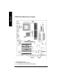
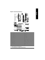
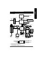
KT400 Series Motherboard Layout
GA-7VAXP Ultra
KB_MS
CK_RATIO
COMA
LPTGAM E
LINE_OUTMIC_IN
USB
IT8 705
AC97
BATTERY
Backup
BIOS
SYS
FAN
VT8 235
KT400
SOCKET A
CPU
FAN
ATX
FLOPPY
IDE1
IDE2
PCI1
PCI2
PCI3
RTL
810 0BL
PCI4
DDR1
AGP
SW1
F_U SB1
LINE_IN
LAN
COMB
CD_IN
PCI5
MAIN
BIOS
DDR2
DDR3
WOL
F_AU DIO
F2_1394F1_1394
CI
PDC
20276 **
IDE4**
IDE3**
IEEE 1394 ***
NB_FAN
F_PANEL
F_U SB2F3-1 394
PWR
FAN
AUX_IN
SUR_CEN
IR
SPDIF_O SPDIF_IN
USB 2.0
PWR_LED
SCR
RAM_LED
SIL3112 *
S_ATA2*
S_ATA1*
K7 Triton 400
FSB333
DDR400+
AGP 8X
VT6 306
***
" * " FOR GA-7VAXP Ultra Only.
" ** " FOR GA-7VAXP Ultra / GA-7VAXP Only.
" *** " For GA-7VAXP Ultra / GA-7VAXP / GA-7VAX1394 Only.

- 9 - Hardware Installation Process
English
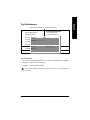
Chapter 2 Hardware Installation Process
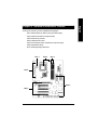
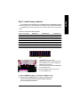
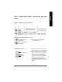
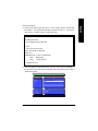
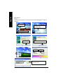
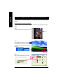
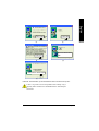
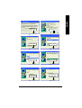
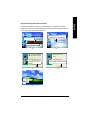
To set up your computer, you must complete the following steps:
Step 1- Set Dip Switch (CK_RATIO) and system Switch (SW1)
Step 2- Install the Central Processing Unit (CPU)
Step 3- Install memory modules
Step 4- Install expansion cards
Step 5- Connect ribbon cables, cabinet wires, and power supply
Step 6- Setup BIOS software
Step 7- Install supporting software tools
Step 3
Step 1
Step 4
Step 5
Step 5
Step 2

- 10 -KT400 Series Motherboard
English
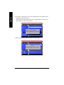
Step 1: Install the Central Processing Unit (CPU)
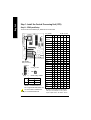
Step1-1: CPU Speed Setup
The clock ratio can be switched by CK_RATIO and refer to below table.
Default Setting :
Auto (X X X X X X)
O: ON / X :OFF
Default Setting: 100MHz
5
1
ON
2 3
4
CK_RATIO
6
SW1
1
ON
SW1 CPU CLOCK
100MHz AUTO
1 ON OFF
MNote: In order to BIOS can auto detecting
when your CPU m utiplier over 18x, please
adjust mutiplier swich in CK Raito to "AUTO."
RATIO 1 2 3 4 5 6
AUTO X X X X X X
(Default)
5x O O X O O O
5.5x X O X O O O
6x O X X O O O
6.5x X X X O O O
7x O O O X O O
7.5x X O O X O O
8x O X O X O O
8.5x X X O X O O
9x O O X X O O
9.5x X O X X O O
10x O X X X O O
10.5x X X X X O O
11x O O O O O O
11.5x X O O O O O
12x O X O O O O
12.5x X X O O O O
13x O O X O X O
13.5x X O X O X O
14x O X X O X O
15x O O O X X O
16x O X O X X O
16.5x X X O X X O
17x O O X X X O
18x X O X X X O
O: ON / X :OFF
CLK_RATIO
You must set SW1 to 100MHz when
you used FSB 200MHz CPU.
100MHz : Fix FSB 200MHz CPU
Auto : Support FSB 266/333 MHz CPU

- 11 - Hardware Installation Process
English
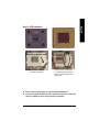
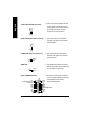
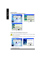
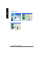
Step1-2: CPU Installation
CPU Top View CPU Bottom View
Socket Actuation Lever
1. Pull up the CPU socket lever
and up to 90-degree angle.
Pin1 indicator
2. Locate Pin 1 in the socket and look
for a (golden) cut edge on the CPU
upper corner. Then insert the CPU
into the socket.
M Please make sure the CPU type is supported by the motherboard.
M If you do not match the CPU socket Pin 1 and CPU cut edge well, it will cause
improper installation. Please change the insert orientation.

- 12 -KT400 Series Motherboard
English
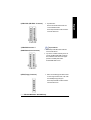
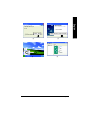
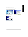
Step1-3:CPU Heat Sink Installation
3. Fasten the heatsink supporting-base
onto the CPU socket on the main-
board.
2. Use qualified fan approved by AMD.
4. Make sure the CPU fan is
plugged to the CPU fan connector,
than install complete.
1. Press down the CPU socket
lever and finish CPU installation.
M Please use AMD approved cooling fan.
M We recommend you to apply the thermal paste to provide better heat
conduction between your CPU and heatsink.
M Make sure the CPU fan power cable is plugged in to the CPU fan connector,
this completes the installation.
M Please refer to CPU heat sink user’s manual for more detail installation
procedure.

- 13 - Hardware Installation Process
English
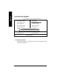
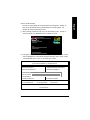
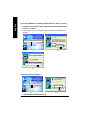
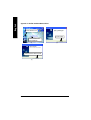
Step 2: Install memory modules
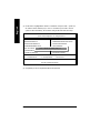
Total Memory Sizes With Unbuffered DDR DIMM
Devices used on DIMM 1 DIMMx64/x72 2 DIMMsx64/x72 3 DIMMsx64/x72
64 Mbit (2Mx8x4 banks) 128 MBytes 256 MBytes 384 MBytes
64 Mbit (1Mx16x4 banks) 64 MBytes 128 MBytes 192 MBytes
128 Mbit(4Mx8x4 banks) 256 MBytes 512 MBytes 768 MBytes
128 Mbit(2Mx16x4 banks) 128 MBytes 256 MBytes 384 MBytes
256 Mbit(8Mx8x4 banks) 512 MBytes 1 GBytes 1.5 GBytes
256 Mbit(4Mx16x4 banks) 256 MBytes 512 MBytes 768 MBytes
512 Mbit(16Mx8x4 banks) 1 GBytes 2 GBytes 3 GBytes
512 Mbit(8Mx16x4 banks) 512 MBytes 1 GBytes 1.5 GBytes
The motherboard has 3 dual inline memory module(DIMM) sockets. The BIOS will automatically
detects memory type and size. To install the memory module, just push it vertically into the DIMM Slot.
The DIMM module can only fit in one direction due to the notch. Memory size can vary between
sockets.
DDR
1. The DIMM slot has a notch, so the
DIMM memory module can only fit in one direction.
2. Insert the DIMM memory module verticallyinto the
DIMM slot. Then push it down.
3. Close the plastic clip at both edges of theDIMM slots
to lock the DIMM module.
M Reverse the installationsteps when you wish to
remove the DIMM module.
M When STR/DIMM LED is ON, do not install/remove DIMM from socket.
M Please note that the DIMM module can only fit in one direction due to
the one notch. Wrong orientation will cause improper installation.
Please change the insert orientation.

- 14 -KT400 Series Motherboard
English
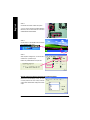
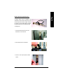
Step 3: Install expansion cards
AGP Card
Please carefully pull out the small white-
drawable bar at the end of the AGP slot when
you try to install/ Uninstall the AGP card.
Please align the AGP card to the onboard
AGP slot and press firmly down on the slot .
Make sure your AGP card is locked by the
small white- drawable bar.
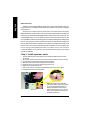
Established on the existing SDRAM industry infrastructure, DDR (Double Data Rate) memory is a
high performance and cost-effective solution that allows easy adoption for memory vendors, OEMs and
system integrators.
DDR memory is a sensible evolutionary solution for the PC industry that builds on the existing
SDRAM infrastructure, yet makes awesome advances in solving the system performance bottleneck by
doubling the memory bandwidth. DDR SDRAM will offer a superior solution and migration path from
existing SDRAM designs due to its availability, pricing and overall market support. PC2100 DDR
memory (DDR266) doubles the data rate through reading and writing at both the rising and falling edge of
the clock, achieving data bandwidth 2X greater than PC133 when running with the same DRAM clock
frequency. With peak bandwidth of 2.664 GB per second, DDR memory enables system OEMs to build
high performance and low latency DRAM subsystems that are suitable for servers, workstations, high-
end PC's and value desktop SMA systems. With a core voltage of only 2.5 Volts compared to
conventional SDRAM's 3.3 volts, DDR memory is a compelling solution for small form factor desktops
and notebook applications.
DDR Introduction
1. Read the related expansion card’s instruction document before install the expansion card into
the computer.
2. Remove your computer’s chassis cover, necessary screws and slot bracket from the computer.
3. Press the expansion card firmly into expansion slot in motherboard.
4. Be sure the metal contacts on the card are indeed seated in the slot.
5. Replace the screw to secure the slot bracket of the expansion card.
6. Replace your computer’s chassis cover.
7. Power on the computer, if necessary, setup BIOS utility of expansion card from BIOS.
8. Install related driver from the operating system.
Page is loading ...
Page is loading ...
Page is loading ...
Page is loading ...
Page is loading ...
Page is loading ...
Page is loading ...
Page is loading ...
Page is loading ...
Page is loading ...
Page is loading ...
Page is loading ...
Page is loading ...
Page is loading ...
Page is loading ...
Page is loading ...
Page is loading ...
Page is loading ...
Page is loading ...
Page is loading ...
Page is loading ...
Page is loading ...
Page is loading ...
Page is loading ...
Page is loading ...
Page is loading ...
Page is loading ...
Page is loading ...
Page is loading ...
Page is loading ...
Page is loading ...
Page is loading ...
Page is loading ...
Page is loading ...
Page is loading ...
Page is loading ...
Page is loading ...
Page is loading ...
Page is loading ...
Page is loading ...
Page is loading ...
Page is loading ...
Page is loading ...
Page is loading ...
Page is loading ...
Page is loading ...
Page is loading ...
Page is loading ...
Page is loading ...
Page is loading ...
Page is loading ...
Page is loading ...
Page is loading ...
Page is loading ...
Page is loading ...
Page is loading ...
Page is loading ...
Page is loading ...
Page is loading ...
Page is loading ...
Page is loading ...
Page is loading ...
Page is loading ...
Page is loading ...
Page is loading ...
Page is loading ...
Page is loading ...
Page is loading ...
Page is loading ...
Page is loading ...
Page is loading ...
Page is loading ...
Page is loading ...
Page is loading ...
Page is loading ...
Page is loading ...
Page is loading ...
Page is loading ...
Page is loading ...
Page is loading ...
Page is loading ...
Page is loading ...
Page is loading ...
Page is loading ...
Page is loading ...
Page is loading ...
Page is loading ...
Page is loading ...
Page is loading ...
Page is loading ...
Page is loading ...
Page is loading ...
-
 1
1
-
 2
2
-
 3
3
-
 4
4
-
 5
5
-
 6
6
-
 7
7
-
 8
8
-
 9
9
-
 10
10
-
 11
11
-
 12
12
-
 13
13
-
 14
14
-
 15
15
-
 16
16
-
 17
17
-
 18
18
-
 19
19
-
 20
20
-
 21
21
-
 22
22
-
 23
23
-
 24
24
-
 25
25
-
 26
26
-
 27
27
-
 28
28
-
 29
29
-
 30
30
-
 31
31
-
 32
32
-
 33
33
-
 34
34
-
 35
35
-
 36
36
-
 37
37
-
 38
38
-
 39
39
-
 40
40
-
 41
41
-
 42
42
-
 43
43
-
 44
44
-
 45
45
-
 46
46
-
 47
47
-
 48
48
-
 49
49
-
 50
50
-
 51
51
-
 52
52
-
 53
53
-
 54
54
-
 55
55
-
 56
56
-
 57
57
-
 58
58
-
 59
59
-
 60
60
-
 61
61
-
 62
62
-
 63
63
-
 64
64
-
 65
65
-
 66
66
-
 67
67
-
 68
68
-
 69
69
-
 70
70
-
 71
71
-
 72
72
-
 73
73
-
 74
74
-
 75
75
-
 76
76
-
 77
77
-
 78
78
-
 79
79
-
 80
80
-
 81
81
-
 82
82
-
 83
83
-
 84
84
-
 85
85
-
 86
86
-
 87
87
-
 88
88
-
 89
89
-
 90
90
-
 91
91
-
 92
92
-
 93
93
-
 94
94
-
 95
95
-
 96
96
-
 97
97
-
 98
98
-
 99
99
-
 100
100
-
 101
101
-
 102
102
-
 103
103
-
 104
104
-
 105
105
-
 106
106
-
 107
107
-
 108
108
-
 109
109
-
 110
110
-
 111
111
-
 112
112


Gigabyte GA-7VAXP Ultra User manual
- Category
- Motherboards
- Type
- User manual
- This manual is also suitable for
Ask a question and I''ll find the answer in the document
Finding information in a document is now easier with AI
Related papers
-
Gigabyte GA-8SIMLFS User manual
-
-
Gigabyte GA-8SQ800 ULTRA User manual
-
Gigabyte GA-7S748 User manual
-
Gigabyte GA-8SG667 User manual
-
Gigabyte GA-8IGMK User manual
-
Gigabyte GA-8IE800 User manual
-
Gigabyte GA-8LD533 User manual
-
Gigabyte GA-8IGML-T User manual
-
Gigabyte 8VM533M-RZ User manual
Other documents
-
Fujitsu GA-7VAXFS User manual
-
Zonet ZUH2215V Quick Installation Manual
-
AMD GA-7VASFS-FS User manual
-
 WinFast NF4K8AB User manual
-
EPOX MU-8KHA+11 User manual
-
VTech i915 Technical Reference Booklet
-
SOYO SY-KT400 Dragon Ultra User manual
-
MATSONIC MS8147C User manual
-
-
VIA Technologies VT8237R User manual
