Installation Manual
For
ToddPod Outdoor Shower Enclosures
Contact us at 888-545-9763 or email us at [email protected] with any questions during the
installation process. Our service team is available 24/7.
Installation Manual
This Manual can be used for all Models
Contact us at 888-545-9763 or email us at
[email protected] with any questions during installation.
Our service team is available 24/7.

Floor Model Options
Tools Required:
Tape Measure, Screw Gun, Level, Pencil, 1/2” Socket Wrench and Silicone.
*All hardware for shower parts are included in part box. #2 Square tip bit is included in door
hardware box.*
You will need to purchase the necessary screws/bolts to mount unit to the ground. If placing
shower on pavers, cement or blacktop; you will need 2” X ¼” Simpson Strong Tie “Titen”
(Approved for 115 MPH Wind zones) or equivalent masonry anchor, washers and a ¼” masonry
drill bit (6 screws for a double unit and 4 screws for a single unit).
If placing your shower on gravel, grass or dirt, we recommend that you use a 6 x 6 pressure
treated wooden base.
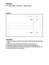
Model STP-1
Model STP-2
Double Models Size: 46”d x 88”w x 88”h, 36”d x 68”w x 88”h
Model DTP-1 Model DTP-2 Model DTP-3
Model DTP-4
Model DTP-5 Model DTP-6 Model DTP-7
Model DTP-8
Single Models Size: 46”d x 46”w x 88”h, 36”d x 36”w x 88”h

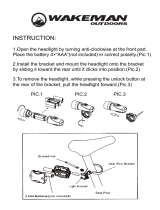
6 X 6 Base
**6 x 6 frames should be no greater than dimension of unit**
Double Unit 6x6 Base:
10 qty. - 5” x 3/8” Galvanized lag bolts
2 qty. – 36” or 46” Pressure Treated Wood (Depending on size of unit)
2 qty. – 68” or 88” Pressure Treated Wood (Depending on size of unit)
Single Unit 6x6 Base:
8 qty. - 5” x 3/8” Galvanized lag bolts
4 qty. - 36” or 46” Pressure Treated Wood (Depending on size of unit)
1. Create a lap joint at 5 ½” in length and 2 ¾” in depth on both ends of each piece of wood.
2. Overlap each cut out connection and fasten with (2) 5” x 3/8” lag bolts.
3. Flip the frame over to ensure a smooth surface for the aluminum frame installation.
4. Dig the wood sub-frame into the ground and make sure it is level and stable around the perimeter. Fill the
interior with 3/8” stone for a French drain.
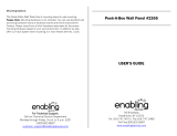
1) Setting Frame and Posts:
a. Remove the base frame from the box and lay on a flat surface where the shower unit will be
installed. For double units make sure the center supports of both frames are in line with each
other and fasten using ¾” self tapping screws. (See PIC 1a)*It is important to determine your
door location, door swing, and all wall locations before unit installation begins.* See Floor Plan
provided with installation manual.
Single Model Door Swing
Double Model Door Swing

b. Remove one set of posts from the post box and place on the frame. The elongated holes at the
base of the post must be parallel with the shower door opening. All posts on shower door side of
unit must be installed parallel to the door opening. The post flange will already be attached to
the post. Lift flange to access where post bolts secure to base frame without removing flange
from post.
c. Using 5/16” x ¾” stainless steel bolts (4 per post) secure post to frame by screwing in bolts
halfway. *Do NOT over tighten! Allow room to move the post slightly this is important to be able
to set the wall panels. (See PIC 1c)
2) Installing Wall Panels and Post Bracket:
a. On the face of the post where the wall/header will sit measure down 1” from the top of the post
(make a mark). Just below the mark measure 1” from the side of the post and mark (forming a T).
(See PIC 2a) *Important: This will keep header and top of the wall panel aligned.*
b. Align the top of the post bracket with the top of the “T” and center the post bracket screw hole
with the center of the “T”. Attach the bracket using the self tapping ¾” stainless steel screw
(provided in wall panel box). (See PIC 2b)
c. Measure down from the TOP of the post bracket 72 1/2” and make a mark. Above that line
measure in 1” from the side of the post and make another mark forming an upside down “T”.
(See PIC 2c)
d. Align the bottom of the post bracket with the bottom line of the upside down “T” and center the
post bracket screw hole with the center of the upside down “T”. Attach the bracket using the self
tapping ¾” stainless steel screw (provided in wall panel box). (See PIC 2d)
e. Repeat steps 2a thru 2d on adjacent post where wall panel will be installed.
PIC 1a PIC 1c
PIC 2b
PIC 2c
PIC 2d
PIC 2a

f. Set the wall panel into the bottom brackets first, and then pull the posts away at the top. The top
of the wall panel should clear the top wall bracket and fit snug. If the wall panel does not clear
the top panel bracket and fit snug loosen the post bolts. (See PIC 2f)
g. Fasten the wall panel to the brackets using the self tapping ¾” stainless steel screws on all four
corners of the wall panel. *All screws must be facing the interior of the shower & centered on
bracket. (See PIC 2g)
h. Continue this process until all wall panels are installed. If there is any part of the shower facing
an existing structure, and a wall panel is not being installed, a header will be provided in order
for you to secure the two posts. This header will also need to be installed on the top of the door.
Follow steps 2a and 2b to attach the brackets, and then attach the header (open side up) to the
brackets using self tapping ¾” stainless steel screws. (See PIC 2h)
i. Tighten the bottom bolts of each post to secure the unit. The post must be tightened evenly to
ensure unit will be level.
3) Installing Half Wall Panel (Double Units):
a. Only 3 post brackets are required for the half wall. 2 for the half wall
header and 1 for the bottom of the half wall. Refer to steps 2a thru 2d for
post bracket installation.
b. Install the half wall panel into the header so that the end of the header is
flush with the end of half wall so that the tab is facing toward the center
of the header.
c. Fasten a self tapping screw through the top of the header into the tab of
the half wall to secure the frame to the header. The screw should go
14 ½” in from the end of the header that’s flush with end of the half wall.
Then install the half wall and header into the wall brackets using the self
tapping screws. (See PIC 3c)
4) Secure Shower Unit to Surface
a. If you are placing your shower on pavers, cement or blacktop; attach the frame to a level surface
using 2” x ¼” Simpson Strong Tie “Titen” (Approved for 115 MPH wind zones). You will need 6
screws for a double unit and 4 screws for a single unit. Plastic shims are recommended to avoid
contact.
b. Before screwing down the frame, use plastic washers or P.V.C shims to level frame. *The frame
must be level prior to fastening*.
PIC 3c
PIC 2f
PIC 2g
PIC 2h

If placing your shower on a wooden surface; attach the frame using 4” x 3/8” lag bolts. You will
need 6 qty. for double unit and 4 qty. for a single unit. *The frame must be level prior to
fastening*.
5) Installing the Roof:
*2 people are recommended for this step.*
a. Assemble the roof on the ground by sliding the louvers
(See PIC 5a.) For privacy purposes determine the
direction you would like the louvers to go prior to
sliding them on.
b. If you are using the pergola end caps it is
important to use silicone to secure them to the
cross beams in the front of the shower (door
side). (See PIC 5b-1) Secure the end caps (flat)
with silicone to the back side of the cross
beams. (See PIC 5b-2)
c. Space cross beams approx. 9 ¾” apart. With
one person standing inside the shower to guide
and support the roof, lift the roof and slide it
into place. Make sure the back of the cross
beams are flush with the shower unit before
proceeding. The end cross beams should sit just inside your top wall brackets. Check
measurement on cross beams to ensure they are still at approx. 9 ¾” apart. (See PIC 5c)
d. Use the L brackets and self tapping ¾” stainless steel screws to attach each cross beam to the
inside of a wall panel or header on both the front and rear of the shower. (See PIC 5d)
e. It is time to secure the peek a boo bracket on
either side of the roof. Place the pre-drilled
holes against cross beams. Center it to where
it should be (approximately 5” on either side).
Use self tapping ¾” stainless steel screws
in the pre-drilled holes to secure the peek a boo
bracket to the louvered roof. (See PIC 5e)
PIC 5a
PIC 5b-1
PIC 5b-2
PIC 5c PIC 5d
PIC 5e

6) Installing Shower Door:
*Note: For DTP-7, 8,9 & 10 Models – Door swing must be in the same direction for Handle to Align
Properly.
Make sure the unit is secured to the surface and level so the door sits plumb. Determine your door swing
prior to moving on. All screws for the door are included in the door hardware box.
a. Follow steps from 2a & 2b to ensure the header bracket
is installed PRIOR to door installation.
b. Measure in 7/8” from outside of post and draw three
separate marks going down the side of the post where
the door hinge will sit. Hinge pin must be on outside of
post when door is closed. (See PIC 6b)
*Important: This will ensure the hinge is secured
straight on the post.*
c. Install the door hanger on the top corner (hinge side) of the front of the door.(See PIC 6c-1)
Hang the door so that the door hanger is on the top of post that the hinge will be on so that the
door will be in the fully open position. (See PIC 6c-2) Door should align with the lines that were
drawn in step 5b. Using the self tapping stainless steel screws, attach the hinge to the post
(inside) into the pre-drilled holes. (See PIC 6c-3)
* Must start with the bottom screw and work your way up to the top screw.*
7) Installing the Lock:
a. Remove the lock from the door hardware box and
ensure deadbolt is in the closed position. *Important*
b. Separate the door lock and place spacer over door
lock so that the flat side of the spacer is against rubber
seal while positioning the notched end of the spacer
toward the dead bolt. (See PIC 7b)
PIC 6c-2 PIC 6c-3
PIC 7b
PIC 6b
PIC 6c-1

c. Insert spacer on the inside of the door (See PIC 7c-1). Attach the other half by matching the
notched pin into the opening of the red leaver. Secure to the door by using the four ¾” stainless
steel screws provided. (See PIC 7c-2) Use the two ¼” stainless steel screws provided to secure the
lock to the side of the door. (See PIC 7c-3)
d. Hold the door in the closed position and mark the proper location to attach the strike plate. (See
PIC 7d)
e. Attach the strike plate using the self tapping ¾” stainless steel screws. Make sure edge is flush
with front edge of post and the beveled edge is on the outside so the door closes properly. (See
PIC 7e)
f. Attach the door stop to the post behind the strike plate. It is important to have the center hole of
door stop align with the middle of the strike plate. (See PIC 7f)
*IMPORTANT: YOU ARE READY TO ADJUST POSTS FOR EQUAL REVEAL AND TIGHTEN THE POST BOLTS TO THE
FRAME
8) Installing the Towel Bar/Hook Bar:
a. Measure and mark 2 adjacent posts (the desired
Height) on the side where the towel bar/hook bar
will be placed. Use stainless steel screws provided.
(See PIC 8a.)
PIC 7c-1
PIC 7c-2
PIC 7d PIC 7f
PIC 8a
PIC 7c-3
PIC 7e

9) Installing the Floor:
a. For a single base frame start at either edge of the frame, lay one of the pre-assembled floor
panels in place; followed by the matching interlocking panel. Note the floor planks should run
perpendicular to the frame joists. (See PIC 9a)
b. For the expander frame the floor panel with the smaller plank is to go on the side away from the
single base floor with the floor planks perpendicular to the frame joists. Install the remaining
floor panel in the open space next to the single base floor frame.
10) Install the Post Caps:
a. Use silicone to secure post cap to the
top of each post. (See Pic 10a)
Cleaning/Maintenance:
-It is recommended to use any multi-purpose cleaner with a soft rag and/or soft brush when cleaning the
unit.
PIC 9a
PIC 10a
/