Dometic RM2193 User manual
- Category
- Split-system air conditioners
- Type
- User manual

REFRIGERATION
REFRIGERATORS
Form No. 3317427.000 01/21 | ©2021 Dometic Corporation
WARNING
Cancer and Reproductive Harm
www.P65Warnings.ca.gov
RM2193
EN
Manual Refrigerator
Service Manual ........................2
WARNING: If the information in this manual is not followed
exactly, a fire or explosion may result, causing property
damage, personal injury, or death.
– Do not store or use gasoline or other flammable vapors
and liquids in the vicinity of this or any other appliance.
– WHAT TO DO IF YOU SMELL GAS
• Do not try to light any appliance.
• Do not touch any electrical switch.
• Do not use any phone in your recreational vehicle.
• Clear the recreational vehicle of all occupants.
• Turn off the gas supply tank valve(s) or main gas supply.
• Immediately call your gas supplier for instructions.
If you cannot reach your gas supplier, call the fire
department.
– Have the gas system checked and leakage source
corrected by a qualified installer, service agency,
manufacturer or dealer, or the gas supplier.

2
EN
Contents Manual Refrigerator
1 Explanation of Symbols and Safety
Instructions ............................ 2
1.1 Recognize Safety Information .............2
1.2 Understand Signal Words ................2
1.3 Supplemental Directives .................3
1.4 General Safety Messages ................3
2 Intended Use ........................... 4
3 Troubleshooting ........................ 4
4 General Information ..................... 6
4.1 Tools and Materials .....................6
4.2 Component Locations. . . . . . . . . . . . . . . . . . . 7
4.3 Terminology ...........................7
5 Wiring Diagrams ........................ 8
6 Diagnostic Procedures ................... 8
7 Installation Issues ...................... 13
7.1 Power Issues .........................13
7.2 Gas Pressure Issues ....................13
7.3 Installation Issues ......................13
7.4 Ambient Temperature Issues .............14
7.5 Humidity Issues .......................14
7.6 Altitude Issues ........................14
7.7 RF Interference Issues ..................14
8 Service Procedures ..................... 14
8.1 Removing the Refrigerator from an
Enclosure ............................15
8.2 Performing a Gas Leak Test ..............15
8.3 Replacing the Burner Assembly ..........15
8.4 Cleaning the Jet .......................16
8.5 Replacing the Cooling Unit ..............16
8.6 Replacing the Door ....................17
8.7 Testing the Door Gasket ................17
8.8 Repairing the Door Gasket ..............18
8.9 Adjusting the Position of the Electrode ....18
8.10 Replacing the Electrode ................18
8.11 Replacing the Flue Baffle ................18
8.12 Replacing the Gas Valve ................19
8.13 Testing a Heating Element for Resistance ...19
8.14 Replacing a Heating Element ............20
8.15 Replacing the Piezo ....................20
8.16 Replacing a Switch ....................21
8.17 Replacing the Thermocouple ............21
8.18 Replacing the Thermostat ...............21
8.19 Replacing the Ventilation Fan ............22
8.20 Replacing the Ventilation Fan Switch ......22
9 Disposal ..............................23
10 Replacement Parts .....................23
Contents
Service Center & Dealer Locations
Visit: www.dometic.com
Read these instructions carefully.
1 Explanation of Symbols and
Safety Instructions
This manual has safety information and instructions to
help you eliminate or reduce the risk of accidents and
injuries.
1.1 Recognize Safety Information
This is the safety alert symbol. It is used to alert
you to potential physical injury hazards. Obey all
safety messages that follow this symbol to avoid
possible injury or death.
1.2 Understand Signal Words
A signal word will identify safety messages and property
damage messages, and also will indicate the degree or
level of hazard seriousness.
DANGER!
Indicates a hazardous situation that, if not avoided,
will result in death or serious injury.
PN

3
EN
Manual Refrigerator Explanation of Symbols and Safety Instructions
WARNING
Indicates a hazardous situation that, if not avoided,
could result in death or serious injury.
CAUTION
Indicates a hazardous situation that, if not avoided,
could result in minor or moderate injury.
NOTICE: Used to address practices not related to
physical injury.
I
Indicates additional information that is not related
to physical injury.
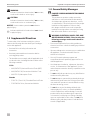
1.3 Supplemental Directives
To reduce the risk of accidents and injuries, please
observe the following directives before proceeding to
service this appliance:
• Read and follow all safety information and
instructions.
• Read and understand these instructions before
servicing] this product.
• The installation must comply with all applicable local
or national codes, including the latest edition of the
following standards:
U.S.A.
– ANSI/NFPA70, National Electrical Code (NEC)
– ANSI/NFPA 1192, Recreational Vehicles Code
– ANSI Z21.19, Absorption Code
Canada
– CSA C22.1, Parts l & ll, Canadian Electrical Code
– CSA Z240 RV Series, Recreational Vehicles
1.4 General Safety Messages
DANGER! CARBON MONOXIDE POISONING
HAZARD.
This product can produce carbon monoxide,
which has no odor and can be life-threatening.
Avoid improper adjustment, alterations, service,
or maintenance. Follow instructions for the proper
installation of this appliance. Failure to obey
this danger notification can result in improper
installation causing carbon monoxide poisoning
that will result in death or serious injury.
WARNING: ELECTRICAL SHOCK, FIRE, AND/
OR EXPLOSION HAZARD. Failure to obey the
following warnings could result in death or
serious injury:
• Disconnect all power before working within any
electrical enclosure or before handling any electrical
connections.
• If powered diagnostics are necessary to troubleshoot
the appliance, a trained and certified service
technician is required.
• Use only Dometic replacement parts and
components that are specifically approved for use
with the appliance.
• Avoid improper installation, adjustment, alterations,
service, or maintenance of the appliance. Service
and maintenance must be done by a qualified service
person only.
• Do not modify this product in any way. Modification
can be extremely hazardous.
• Do not attempt to operate this product by both gas
and electricity at the same time. Always ensure that
one method of operation is turned off before using
the alternate energy source.
• Do not allow anyone (including children) with
reduced physical, sensory or mental capabilities,
or lack of experience and knowledge, to use this
product unless they have been given supervision
or instruction (concerning use of this product) by
a person responsible for their safety. Do not allow
children to play with the product or with the fixed
controls (if applicable).

4
EN
Intended Use Manual Refrigerator
• This product is equipped with a three-prong
(grounding) plug for protection against shock
hazards. This product should be plugged directly into
a three-prong receptacle that provides grounding in
compliance with all applicable electrical codes. Do
not cut or remove grounding prong from plug.
• Before refueling or parking near a gasoline pump,
make sure all LP gas appliances are shut off.
• Do not store or use gasoline, oil- or gasoline-soaked
rags, or flammable liquids in the service area behind
the refrigerator or in the vicinity of this or any other
gas appliance.
WARNING: ABSORPTION-COOLING SYSTEMS:
FIRE, BURN, OR INHALATION HAZARD.
Do not fracture or puncture cooling unit. The
cooling unit is under pressure and contains
ammonia, sodium chromate, and other chemicals.
Repeated or prolonged exposure to sodium
chromate could cause organ damage or cancer.
Exposure to a high concentration of ammonia
refrigerant could cause pulmonary edema (fluid in
lungs); chemical burns to eyes, lungs, and skin; and
could cause a fire (when exposed to open flame).
If the refrigerator stops working and/or emits an
ammonia smell, immediately turn the refrigerator off
(if it is safe to do so), leave the vicinity, and contact a
qualified service center. Failure to obey this warning
could result in death or serious injury.
WARNING: PRESSURE HAZARD.
Do not place carbonated liquids, glass containers,
or sealed bottles in the freezer. Liquids expand
when frozen and could cause the container to
explode. Failure to obey this warning could result in
death or serious injury.
WARNING: LIFTING HAZARD.
Use proper liing technique and control when
liing the product. Failure to obey this warning
could result in death or serious injury.
CAUTION: BURN, FROSTBITE , OR FROSTNIP
HAZARD. Failure to obey the following
cautions could result in minor or moderate
injury:
• Do not touch cold surfaces (or stored items) in freezer
compartment with damp or wet skin. Skin could stick
to cold surfaces and freeze.
• Cooling unit piping may be hot. Allow time to cool
before touching.
2 Intended Use
This service manual is intended for use by OEM Service
Center and dealer technicians. It is not intended for use
by RV owners, or those unfamiliar with the workings of
refrigerators used in the RV industry.
Readers of this manual are assumed to have a basic
understanding of RV refrigerator best practices and
experience in the proper use of the tools and materials
related to the installation, operation, maintenance, and
service of the refrigerator equipment used in the RV
industry.
The refrigerator service manual is a resource created to
help service technicians identify the refrigerator product
by serial number, diagnose an operational issue, and
efficiently and effectively process warranty claims.
For applicable installation instructions, authorized
service center information, or specific warranty
information, visit www.dometic.com.
For applicable exploded parts views or service kit
information, visit www.dometic.com/en-us/us/for-
business.
3 Troubleshooting
This section has tables showing the main causes for
refrigerator issues.
Review the “Troubleshooting Table” on page 5
to help you identify the suspected operational issue,
the potential causes, and the diagnostic procedure
associated with those issues.
Refer to the “Diagnostics Table” on page 6 for links
to specific refrigerator components that show diagnostic
tasks to help you confirm the suspected operational
issue and potential cause.
Remember to check the basics, including contributing
issues, before replacing any parts. Refer to “Installation
Issues” on page 13 for more detail.

5
EN
Manual Refrigerator Troubleshooting
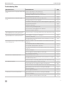
Troubleshooting Table
Operational Issue Potential Reason Page
The refrigerator does not operate in AC or DC
mode.
The AC or DC switch is in the off position. 11
The AC or DC voltage is too low or absent. 13
The wiring is faulty, has shorted, or is mis-wired. 8
The heating element is defective. 10
The refrigerator does not operate in gas
mode.
The knob on the gas valve is set to the off position. 10
The gas pressure is too low or absent. 13
The altitude is affecting the operation of the refrigerator in gas mode. 14
The gas valve is defective. 10
The burner is blocked. 8
The piezo is not generating a spark. 11
The electrode is out of alignment or is defective. 9
The thermocouple is defective. 11
The refrigerator does not get cold enough in
AC mode but does in DC or gas mode.
The thermostat is not operating within the proper temperature range. 11
The refrigerator does not get cold enough in
gas mode but does in AC or DC mode.
The flue baffle is out of place or damaged. 10
The burner is blocked. 8
The temperature level set by the knob on the gas valve is too low for
the ambient temperature.
10
The refrigerator does not get cold enough in
any operating mode.
Improper installation caused an imbalance in the airflow around the
refrigerator.
13
The refrigerator level is not within tolerance. 13
The ventilation fan/fan switch is defective. 12
The ambient temperature is preventing the proper functioning of the
refrigerator.
14
The door is warped. 9
The door gasket is cracked, warped, or has a gap. 9
The cooling unit is defective. 9
The fresh food compartment freezes. The thermostat is set too cold. 11
The temperature level set by the knob on the gas valve is too high for
the ambient temperature.
10
The thermostat is not operating within the proper temperature range. 11
Frost builds up rapidly. The door has been open too oen or too long. 9
Food was placed in the refrigerator while it was still warm. N/A
The thermostat is not operating within the proper temperature range. 11
High humidity in the environment is causing frost buildup. 14
The door is warped. 9
The door gasket is defective. 9
Condensation forms around the frame. High humidity in the environment is causing frost buildup. 14
The door is warped. 9
The door gasket is cracked, warped, or has a gap. 9

6
EN
Troubleshooting Manual Refrigerator
Operational Issue Potential Reason Page
There is a strong smell of ammonia. The cooling unit is defective. 9
There is a loud gurgling noise coming from
the cooling unit.
The cooling unit is defective.
Diagnostics Table
Component Page
Burner Assembly 8
Cooling Unit 9
Door 9
Electrode 9
Fan/Fan Switch 12
Flue Baffle 10
Gas Valve 10
Heating Element 10
Piezo 11
Switch (AC) 11
Switch (DC)
Thermocouple 11
Thermostat 11
Ventilation Fan/Switch 12
4 General Information
This section provides reference information on the tools,
components, and terminology associated with the
refrigerator.
4.1 Tools and Materials
Dometic recommends that the following tools and
materials be used while servicing the refrigerator:
Recommended Tools
Flat-Bladed Screwdriver Heat Gun
Multimeter - DC/AC
Amperage, DC/AC Voltage,
Millivolts, Ohms
Substance Temperature
Thermometer
U-Tube Manometer
Needle Nose Pliers Wrenches
Phillips Head Screwdriver

7
EN
Manual Refrigerator Troubleshooting
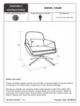
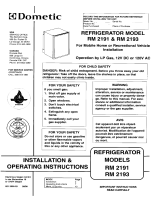
4.2 Component Locations
Figure 1 shows the general component locations. Actual
model component locations may vary.
t
w
e
q
a
r
s
u
y
i
o
t
1 Component Locations
q
Flue Baffle
u
Switch (AC)
w
Cooling Unit
i
Thermostat Piezo
e
Electrode
o
Thermocouple
r
Heating Element
a
Gas Valve
t
Burner Assembly
s
Thermostat
y
Switch (DC)
4.3 Terminology
Term Definition
2-Way
A refrigerator designed to work on either
LP gas or 120VAC
3-Way
A refrigerator designed to work on LP
gas, 12VDC, or 120VAC
Baffle Box
A box created to meet ventilation
clearances at the rear of the refrigerator
Baffle
Extension
A "false wall" extending off of a box baffle
to ensure strong air to the condensing
fins
Burner Tube
A tube welded to the burner that
conducts heat during gas operation to
provide proper heat exchange to the
cooling unit
Cooling Unit
A sealed ammonia-based absorption
cooling system
Electrode
Passes the spark from the piezo through
the high tension wire to the burner where
the spark ignites the LP gas
Flue Baffle
Installed within the burner tube to slow
heat rise and spread heat along the
burner tube
Gas Valve
Controls LP gas flow and the temperature
of the refrigerator during gas operation
Heating
Element
Provides a specific amount of BTUs of
heat to the burner for electric operation
Piezo A manual spark generator
Thermocouple
A flame detection device that uses
resistance to keep fuel flowing for gas
operation
Thermostat
Controls the temperature of the
refrigerator during electric operation
Ventilator Fan
Fan positioned in the rear of the
refrigerator to circulate air and help the
cooling unit function properly

8
EN
Wiring Diagrams Manual Refrigerator
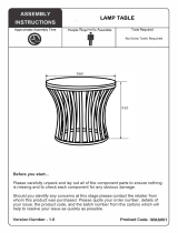
5 Wiring Diagrams
This section provides the wiring specification for the
RM2193 refrigerator.
2 RM2193 Wiring Diagram
6 Diagnostic Procedures
This section has information to help you identify
various operational issues by diagnosing the individual
component parts.
Remember to check the basics, including contributing
issues, before replacing any parts. Refer to “Installation
Issues” on page 13 for more detail.
Component Diagnostic Question Action Based On Status Page
Burner Assembly
Does the refrigerator not operate in gas
mode?
Does the refrigerator not get cold
enough in gas mode but does in AC or
DC mode?
1. Inspect the burner and the area around
the burner for blockages. Clear any
blockages.
2. Inspect the burner slots for clogs. Clean
any that are clogged.
7
3. Clean the burner jet.
4. Turn on the refrigerator in gas mode.
5. Confirm that the flame from the burner is
blue and steady.
16
6. If the burner cannot be unclogged or if it
appears damaged, replace the burner.
15

9
EN
Manual Refrigerator Diagnostic Procedures
Component Diagnostic Question Action Based On Status Page
Cooling Unit
Does the refrigerator not get cold
enough in any operating mode?
Perform a diagnostic on the power supply. 13
Perform a diagnostic on the gas pressure if the
problem occurs during gas operation.
Perform a diagnostic on the ventilation fan(s),
if installed.
12
If the problem persists, replace the cooling
unit.
16
Is a loud gurgling noise coming from the
cooling unit?
Replace the cooling unit.
Is there a strong smell of ammonia?
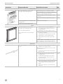
Door
Does the refrigerator not get cold
enough in any operating mode?
Does frost build up rapidly?
Does condensation form around the
frame?
1. Inspect the door and door gasket for
any damage that would prevent it from
closing properly.
2. If damage is observed, replace the door.
17
1. Test the door gasket.
2. If the gasket is weak at any point, repair it.
3. Aer 24 hours, test the gasket again.
4. If the gasket remains weak, replace the
door.
Confirm with the owner that the door has not
been held open or opened oen enough to
allow a substantial volume of warm air to enter.
N/A
Electrode
Does the refrigerator not operate in gas
mode?
1. Inspect the ceramic insulator for cracks or
breaks in the ceramic casing.
I
A hair line crack at the electrode can be
difficult to see.
2. If cracks or breaks are observed, replace
the electrode.
7
1. Confirm that the electrode is securely
held by its clip.
2. Confirm that the tip of the electrode is
positioned 3/16in. (4.8mm) from the
slots in the burner.
3. If the electrode is out of position, adjust it.
18
1. Turn on the refrigerator in gas mode and
confirm that the electrode generates a
spark.
2. If the electrode fails to generate a spark,
replace it.

10
EN
Diagnostic Procedures Manual Refrigerator
Component Diagnostic Question Action Based On Status Page
Flue Baffle
Does the refrigerator not get cold
enough in gas mode but does in AC or
DC mode?
1. Confirm that the flue baffle is properly
positioned in the burner tube.
2. Inspect the flue baffle for damage.
3. If damaged is observed, replace the flue
baffle.
18
Gas Valve
Does the refrigerator not operate in gas
mode?
Confirm that the knob on the gas valve is set
to on.
7
Perform a diagnostic on the gas pressure. 13
Perform a diagnostic on the burner assembly. 8
Perform a diagnostic on the flue baffle. 10
Perform a diagnostic on the piezo. 11
If the problem persists, replace the gas valve. 19
Does the refrigerator not get cold
enough in gas mode but does in AC or
DC mode?
Does the fresh food compartment freeze?
Adjust the knob on the gas valve to the
appropriate setting for the operating
conditions.
I
If the ambient temperature is above 80°F
(27°C), or the door of the refrigerator is
opened frequently, the knob should be
set to high.
N/A
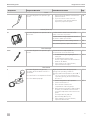
Heating Element
Does the refrigerator not operate in AC or
DC mode?
1. Check the part number of the heating
element against the parts list for the
refrigerator model.
2. If the number does not match, replace the
heating element with the correct part.
N/A
Set the thermostat to the coldest position (7)
and confirm that the voltage supplied to the
heating element is within specification.
• AC heating element: 103.5–126.5VAC
• DC heating element: 10.5–22VDC
13
1. Inspect the heating element for cracks or
breaks.
2. If damage is observed, replace the
heating element.
19
1. Confirm that the resistance of the heating
element is within specification.
2. If the resistance is out of specification,
replace the heating element.

11
EN
Manual Refrigerator Diagnostic Procedures
Component Diagnostic Question Action Based On Status Page
Piezo
Does the refrigerator not operate in gas
mode?
1. Depress the piezo button several times in
quick succession.
2. If you do not hear a click or do not
feel resistance each time the button is
depressed, replace the piezo.
20
Switch (AC or DC)
Does the refrigerator not operate in AC or
DC mode?
Confirm that the switch for the AC or DC
power is set to the on position.
7
Confirm that the voltage supplied to the AC or
DC switch is within specification.
13
Perform a diagnosis on the heating element. 10
If the problem persists, replace the switch. 21
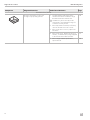
Thermocouple
Does the refrigerator not operate in gas
mode?
Clean the thermocouple tip with an
alcohol-based solvent and let air dry.
7
1. Confirm that the gas is lighting but not
staying lit.
2. Confirm that the voltage of the
thermocouple while in the burner flame is
between 14–30mV.
3. If the voltage is out of specification,
replace the thermocouple.
21
Thermostat
Does the refrigerator not get cold
enough in AC mode but does in DC or
gas mode?
Does the fresh food compartment freeze?
Does frost build up rapidly?
Adjust the thermostat to the appropriate
setting for the operating conditions.
I
If the ambient temperature is above 80°F
(27°C), or the door of the refrigerator is
opened frequently, the thermostat should
be set to 7.
7
1. Set the refrigerator to AC operation.
2. Set the thermostat to 5.
3. Place a bottle of water in the
compartment of the refrigerator.
4. When the thermostat turns off the heating
element, use a substance thermometer
to test the temperature of the water in the
bottle.
The temperature should read
approximately 40°F (4°C).
5. If the reading is out of specification,
replace the thermostat.
21

12
EN
Diagnostic Procedures Manual Refrigerator
Component Diagnostic Question Action Based On Status Page
Ventilation Fan/Switch
Does the refrigerator not get cold
enough in any operating mode?
1. Confirm that the temperature at the
ventilator fan switch is within the range
that will activate the ventilator fan.
I
Installation location varies by model
and installer. The temperature range for
activation varies by model.
2. If the temperature is within specification,
does the fan switch close the circuit.
3. If the circuit does not close, replace the
fan switch.
22
4. If the circuit closes, but the fan does not
activate, confirm that the voltage supplied
to the fan is between 10.5–22VDC.
13
5. If the voltage is within specification,
replace the fan.
22

13
EN
Manual Refrigerator Diagnostic Procedures
7 Installation Issues
NOTICE: Improper clearances and/or ventilation can
lead to high ambient temperature, causing cooling
issues and possible damage to equipment electronics.
Many refrigerator problems are caused by issues outside
of the product itself. When diagnosing a refrigerator
problem, always check the issues described in this
section before replacing components.
Operational Issue Potential Issue
The refrigerator does not operate in
gas mode.
Gas Pressure
The refrigerator does not operate in
AC or DC mode.
The refrigerator cools insufficiently
during AC operation, but cools
properly during gas and DC
operation.
The refrigerator cools insufficiently
during DC operation, but cools
properly during AC and gas
operation.
Power
The refrigerator does not get cold
enough in any operating mode.
Improper
Installation
Ambient
Temperature
The refrigerator does not operate in
gas mode.
Altitude
The fresh food compartment freezes.
Frost builds up rapidly.
Humidity
7.1 Power Issues
The following checks should be made using the battery,
converter, or generator, where applicable. Do not
use a test light, as it does not provide enough useful
information for a proper diagnosis.
Use a digital multi-meter to take readings. Check that the
DC power to the refrigerator is between
10.5–18VDC for DC operation, testing with the interior
lights of the RV both on and off.
Check that the AC power to the refrigerator is between
103.5–126.5VAC for AC operation.
7.2 Gas Pressure Issues
Check that the gas pressure is between
10.5–11.5in.W.C., ideally as close to 11in.W.C. (at
the refrigerator) as possible. Perform the check with
a minimum of 50% (ideally 100%) of other gas-fired
appliances operating while the refrigerator is in
operation. The pressure should be tested using a U-tube
manometer. If using a digital-type manometer, calibrate it
oen with a U-tube manometer.
Check the outside air temperature. As the air gets
colder, it reduces the capacity of the liquid propane (LP)
tank and the gas pressure is affected by a combination of
the fill level of the LP tanks and the ambient temperature
outside.
To raise the tank temperature and increase the capacity
of the tank:
1. Place an insulated, fire-resistant blanket over the
tanks.
2. Place an illuminated 75W light bulb under the
blanket.
The temperature of the bottle should rise 10–20°F
[(-12)–(-7)°C] over a brief period of time, which increases
tank capacity.
7.3 Installation Issues
Specific clearances are required during the installation
of the refrigerator. Check the installation manual for the
refrigerator to find the proper dimensions, and ensure
that the existing installation location complies with the
requirements. In addition, check for these potential
installation issues:
• Air space: aer installing the refrigerator within the
cabinetry, there should be less than 0.5in. (13mm) of
open air space on the sides and top of the refrigerator
or performance issues can occur. If there is any
open air space around the refrigerator, fill the space
with insulation. There should be no more than 1in.
(25mm) of space between the cooling unit and the
side wall of the RV. If there is more than 1in. (25mm)
of space, install a baffle box to fill the extra space

14
EN
Service Procedures Manual Refrigerator
• Fan(s): when installing the refrigerator with two side
wall vents (typically slide-out room installations),
a ventilator fan must be installed at the rear of the
refrigerator as close to the center as possible to assist
with airflow.
• Baffle Extension: when installing the refrigerator
with two side wall vents (typically slide-out room
installations) and the outer edge of the cooling unit
more than 1in. (25mm) from the sidewall of the RV,
install a baffle extension below the fins. . Start at
the lower portion of the upper vent and lead up to
between 0.25–0.50in. (6–13mm) away from the
bottom of the condensing fins to ensure a strong
airflow is maintained directly to and through the fins.
• Deflector shield: when installing the refrigerator
with two side wall vents (typically slide-out room
installations), install a deflector shield air baffle
(turning vein) above the condensing fins to assist with
deflecting the air sideways out of the upper side wall
vent aer the air passes through the fins.
• Leveling: the refrigerator should be set at 3° from
le to right and 6° from front to back. Level the
refrigerator within this tolerance setting.
7.4 Ambient Temperature Issues
The ambient temperature can impact the performance
of the refrigerator. As the ambient temperature rises, the
air temperature around the cooling unit rises and may
result in decreased cooling performance if the unit is not
installed and ventilated according to specification. Refer
to “Installation Issues” on page 13 for more details.
I
If the ambient temperature is below 32°F(0°C)
operating the refrigerator may damage the cooling
unit.
7.5 Humidity Issues
High levels of humidity can impact the cooling
performance of the refrigerator and can cause
condensation and frost build up if the doors are opened
frequently.
7.6 Altitude Issues
The gas system on the refrigerators are not designed
to operate at extremely high altitude. The higher the
refrigerator is in altitude, the more chance there is of
improper gas operation until the refrigerator is brought
to a lower altitude.
7.7 RF Interference Issues
Supply the refrigerator with straight-line DC voltage from
a different 12VDC source and deaden the RV (unplug
shore cord and disconnect the batteries), this will
eliminate interference.
8 Service Procedures
WARNING: ELECTRICAL SHOCK, FIRE, AND/
OR EXPLOSION HAZARD. Failure to obey the
following warnings could result in death or
serious injury:
Aer service, perform a leak check on the gas
system, like a pressure drop test. Verify that there
is a sufficient gas supply before attempting to
light any burner. Air in the line will significantly
delay the burner ignition and a burner may light
unexpectedly as the air in the line clears out and is
replaced by LP gas.
This section has information to help you access the
components for diagnosis and service.
Remember to check the basics, including contributing
issues, before replacing any parts. Refer to “Installation
Issues” on page 13 for more detail.

15
EN
Manual Refrigerator Service Procedures
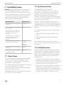
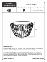
8.1 Removing the Refrigerator from
an Enclosure
3 Removing the Refrigerator from an Enclosure
1. Disconnect the unit from all power sources (120VAC
and 12VDC).
2. Turn off the LP gas supply to the refrigerator.
3. Disconnect the LP gas line from the refrigerator. Cap
the line and confirm there are no LP gas leaks. Refer
to “Performing a Gas Leak Test” on page 15 for
more details.
4. Remove the screws anchoring the refrigerator to the
enclosure.
5. Slide the refrigerator out of the enclosure.
6. Perform these steps in reverse to replace the
refrigerator in the enclosure.
7. Confirm there are no LP gas leaks. Refer to
“Performing a Gas Leak Test” on page 15 for more
details.
8.2 Performing a Gas Leak Test
WARNING: FIRE AND/OR EXPLOSION
HAZARD.
Do not use matches, candles, or other sources of
open flame when checking for gas leaks. Failure to
obey this warning could result in death or serious
injury.
1. Turn on the LP gas.
2. Locate the component for testing. See “Component
Locations” on page 7.
3. Place a non-corrosive leak detection fluid into a
spray bottle.
4. Lightly spray the component with the fluid.
5. Look for bubbles forming on the component.
The appearance of bubbles indicates a leak in the
component.
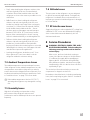
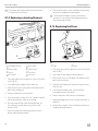
8.3 Replacing the Burner Assembly
y
t
w
e
r
q
i
u
4 Removing the Burner Assembly
q
Shielding
t
Clip
w
Burner Tube
y
Screw
e
Washer
u
Thermocouple
r
Burner Jet
i
Electrode

16
EN
Service Procedures Manual Refrigerator
1. Disconnect the unit from all power sources (120VAC
and 12VDC).
2. Turn off the LP gas supply to the refrigerator and cap
the gas line.
3. Remove the screw securing the shielding around the
burner assembly.
4. Remove the screw and washer securing the burner
assembly to the burner tube.
5. Slide the burner assembly out of the burner tube.
6. Remove the screw securing the clip that holds the
thermocouple and electrode in position.
7. Disconnect the gas line from the burner assembly.
8. Remove the defective burner assembly.
9. Perform these steps in reverse with a new burner
housing to complete the replacement.
10. Confirm there are no LP gas leaks. Refer to
“Performing a Gas Leak Test” on page 15 for more
details.
8.4 Cleaning the Jet
q
w
5 Removing the Jet
q
Gas Line
w
Jet
1. Perform the steps in “Replacing the Burner
Assembly” on page 15 to access the jet.
2. Disconnect the gas line from the jet.
3. Remove the jet.
4. Soak the jet in an alcohol-based solvent for one hour.
5. Remove it from the cleaner and use compressed air
to blow out any residual deposits. Let it air dry.
I
Do not stick any object into the jet as it may cause
damage.
6. Perform these steps in reverse to reassemble the
burner assembly.
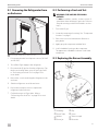
8.5 Replacing the Cooling Unit
6 Removing the Defective Cooling Unit
1. Perform the steps in “Removing the Refrigerator from
an Enclosure” on page 15.
2. Remove the handles (if needed) and lay the
refrigerator face down on a protected surface.
3. Remove the screws securing the outside frame of the
cooling unit to the box of the refrigerator.
4. Remove the heating elements from their pockets in
the cooling unit and set aside to re-use.
5. Pull the flue baffle from the top of the burner tube of
the defective cooling unit and set aside to re-use.
I
Replacement cooling units do not come with a
replacement flue baffle. The flue baffle must be
transferred from the defective cooling unit to the
new cooling unit.
6. Disconnect all wiring from the cooling unit.

17
EN
Manual Refrigerator Service Procedures
7. Refer to steps in “Replacing the Burner Assembly”
on page 15 to remove the burner assembly from
the cooling unit.
8. Pry out the defective cooling unit. Some careful
force may be required.
9. Clean and prepare the inside of the cavity space for
the new cooling unit. A bead of thermal mastic is
required to help the heat transfer process.
10. Apply a thick bead of thermal mastic to the
following:
– The cavity-facing side of the new cooling coils.
– Each inner corner of the recessed cavity from
bottom to top.
– Around the middle of the inner walls of the cavity.
11. Perform these steps in reverse with the new cooling
unit to complete the replacement.
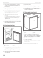
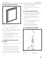
8.6 Replacing the Door
q
w
7 Removing the Door
q
Door Hinge
w
Door
1. Locate and gain access to the door hinges. Refer to
“Removing the Refrigerator from an Enclosure” on
page 15 if removing the refrigerator is necessary
to access the hinges.
2. Remove the bolt from the top hinge securing the
door to the hinge.
3. Remove any washers.
4. Li the door from the bottom hinge pin. It may be
necessary to do this at an angle.
5. Perform these steps in reverse with the new door to
complete the replacement.
8.7 Testing the Door Gasket
q
w
8 Testing the Door Gasket
q
Door
w
Paper
1. Open the refrigerator door and place a piece of
paper, such as a dollar bill, near the door hinge and
between the gasket and the liner of the refrigerator.
2. Close the door on the paper.
3. Try to pull out the paper.
If the paper slips out with no resistance, the gasket is
weak at that point.
4. Repeat this test at points all around the door.

18
EN
Service Procedures Manual Refrigerator
8.8 Repairing the Door Gasket
q
w
9 Repairing the Door Gasket
q
Door
w
Door Gasket
1. Warm the gasket with a heat gun.
I
To avoid melting or damaging the liner, take care to
avoid using heat too close to the plastic liner or in
one spot for too long.
2. Once the gasket is pliable, pull it open and place
a 0.25in. (6mm) dowel rod (or tightly rolled
newspaper) behind the gasket.
3. Close the door with the dowel rod in position and
leave it closed for 24 hours.
8.9 Adjusting the Position of the
Electrode
1. Disconnect the unit from all power sources (120VAC
and 12VDC).
2. Perform the steps in “Replacing the Burner
Assembly” on page 15 to access the electrode.
3. Loosen the screw securing the clip holding the
electrode in position on the burner assembly.
I
To avoid cracking the ceramic insulator, do not try
to adjust the electrode without first loosening the
screw.
4. Adjust the electrode until the tip of the electrode is
3/16in. (4.8mm) from the burner.
5. Perform these steps in reverse to complete the
adjustment.
8.10 Replacing the Electrode
I
On some versions of this model, the electrode is
integrated into the burner assembly. Always use the
product number to aquire the correct part.
1. Perform the steps in “Replacing the Burner
Assembly” on page 15 to release the electrode
from the clip.
2. Perform the steps in “Replacing the Piezo” on page
20 to disconnect the high voltage wire.
3. Remove the defective electrode.
4. Perform these steps in reverse with the new
electrode to complete the replacement.
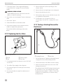
8.11 Replacing the Flue Baffle
q
w
e
r
10 Removing the Flue Baffle
q
T-piece
e
Flue Baffle
w
Screw
r
Burner Tube

19
EN
Manual Refrigerator Service Procedures
1. Perform the steps in “Removing the Refrigerator
from an Enclosure” on page 15 to access the flue
baffle.
WARNING: BURN HAZARD.
The flue baffle may be hot. Allow time for the flue
baffle to cool before touching.
2. Remove the screw securing the T-piece to the burner
tube.
3. Remove the T-piece.
4. Pull the flue baffle out of the burner tube.
5. Perform these steps in reverse with the new flue
baffle to complete the replacement.
The new flue baffle should hang just above the
burner.
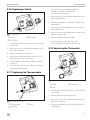
8.12 Replacing the Gas Valve
q
w
e
r
11 Replacing the Gas Valve
q
Knob
e
Thermocouple
w
Nut
r
Gas Valve
1. Disconnect the unit from all power sources (120VAC
and 12VDC).
2. Turn off the LP gas supply to the refrigerator.
3. Disconnect the gas line from the gas valve and cap
the gas line.
4. Disconnect the thermocouple from the bottom of
the gas valve.
5. Remove the knob from the top of the gas valve
selector switch.
6. Remove the nut securing the gas valve to the panel.
7. Remove the defective gas valve.
8. Perform these steps in reverse with the new gas valve
to complete the replacement.
9. Confirm there are no LP gas leaks. Refer to
“Performing a Gas Leak Test” on page 15 for more
details.
8.13 Testing a Heating Element for
Resistance
q
w
12 Testing the Heating Element Wires
q
Heating Element
w
Wire Ends
1. Perform the steps in “Replacing a Heating Element”
on page 20 to remove the heating element.
2. Set the multi-meter to the Ohms resistance setting.
3. Attach a lead of the multi-meter to the ends of the
heating element wires.
The reading for the 120VAC heating element should
be 104Ohms (± 10%). The reading for the 12VDC
heating element should be 1.3Ohms (± 10%). If the
reading is out of specification, it indicates a faulty
heating element.

20
EN
Service Procedures Manual Refrigerator
I
Consult the operating manual for the multi-meter
for specific device function.
8.14 Replacing a Heating Element
q
w
r
e
y
i
u
t
13 Removing a Heating Element from the Flue Stack
q
Heating Elements
t
AC Switch
w
Burner Tube
y
Thermostat
e
Screw
u
Gas Valve
r
DC Switch
i
Gas Line
1. Disconnect the unit from all power sources (120VAC
and 12VDC).
2. Turn off the LP gas supply to the refrigerator.
3. Remove the screws securing the switch panel to the
back of the refrigerator.
4. Pull the switch panel out of position.
5. Trace the wiring from the AC or DC switch to identify
the heating element of the same voltage.
6. Disconnect the wiring of the heating element you
are replacing from the thermostat, ground and
power switch.
7. Remove the defective heating element from the
pocket within the burner tube.
8. Perform these steps in reverse with the new heating
element to complete the replacement.
I
The element should be securely seated in the
pocket. It is easy to place the heating element in
the insulation by mistake.
8.15 Replacing the Piezo
q
w
14 Removing the Piezo
q
Nut
w
Piezo
1. Disconnect the unit from all power sources (120VAC
and 12VDC).
2. Turn off the LP gas supply to the refrigerator.
3. Remove the screws securing the switch panel to the
back of the refrigerator.
4. Slide the switch panel out of position to gain access
to the wiring.
5. From underneath the panel, unscrew the nut
securing the piezo to the panel.
6. Remove the piezo and washer from the panel.
7. Unplug the high-tension wire from the underside of
the piezo.
8. Perform these steps in reverse with the new piezo to
complete the replacement.
Page is loading ...
Page is loading ...
Page is loading ...
Page is loading ...
-
 1
1
-
 2
2
-
 3
3
-
 4
4
-
 5
5
-
 6
6
-
 7
7
-
 8
8
-
 9
9
-
 10
10
-
 11
11
-
 12
12
-
 13
13
-
 14
14
-
 15
15
-
 16
16
-
 17
17
-
 18
18
-
 19
19
-
 20
20
-
 21
21
-
 22
22
-
 23
23
-
 24
24


Dometic RM2193 User manual
- Category
- Split-system air conditioners
- Type
- User manual
Ask a question and I''ll find the answer in the document
Finding information in a document is now easier with AI
Related papers
-
Dometic DM2652 DM2662 DM2663 DM2672 DM2682 DM2683 DM2852 DM2862 DM2872 DM2882 DMR702 DMR702-C DMR702-D DMR702-E RM1350 RM2351 RM2354 RM2451 RM2454 RM2551 RM2554 RM3762 RM3962 User manual
-
-
-
-
-
Dometic DM2852 User manual
-
Dometic RM1350 User manual
-
-
-
Other documents
-
 Julian Bowen BOW201 Assembly Instructions
-
 Julian Bowen WAS001 Assembly Instructions
-
 Julian Bowen WAS002 Assembly Instructions
-
 Julian Bowen COM201 Assembly Instructions
-
Unique UGP-6C SM W User manual
-
Unique UGP-10C SM B Installation guide
-
 Dometic (N-DC) RM2193 User manual
-
Bryant Refrigerator 3163 User manual
-
Norcold 3163 Series User manual
-
Electrolux RM2330 User manual


