
Model F431
SERVICE MANUAL
Manual No. 513605 Rev.3


This manual provides basic information about the machine. Instructions and suggestions are
given covering its operation and care.
The illustrations and specifi cations are not binding in detail. We reserve the right to make
changes to the machine without notice, and without incurring any obligation to modify or pro-
vide new parts for machines built prior to date of change.
DO NOT ATTEMPT to operate the machine until instructions and safety precautions in this
manual are read completely and are thoroughly understood. If problems develop or questions
arise in connection with installation, operation, or servicing of the machine, contact Stoelting.
Stoelting Foodservice Equipment
502 Highway 67
Kiel, WI 53042-1600
U.S.A.
Main Tel: 800.558.5807
Fax: 920.894.7029
Customer Service: 888.429.5920
Fax: 800.545.0662
Email: [email protected]
© 2014 PW Stoelting, LLC
stoeltingfoodservice.com

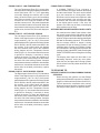
Safety Alert Symbol:
This symbol Indicates danger, warning or caution.
Attention is required in order to avoid serious per-
sonal injury. The message that follows the symbol
contains important information about safety.
Signal Word:
Signal words are distinctive words used throughout
this manual that alert the reader to the existence and
relative degree of a hazard.
CAUTION
The signal word “CAUTION” indicates a potentially
hazardous situation, which, if not avoided, may result
in minor or moderate injury and equipment/property
damage.
A Few Words About Safety
Safety Information
Read and understand the entire manual before
operating or maintaining Stoelting equipment.
This manual provides the operator with information
for the safe operation and maintenance of Stoelting
equipment. As with any machine, there are hazards
associated with their operation. For this reason safety
is emphasized throughout the manual. To highlight
specifi c safety information, the following safety defi ni-
tions are provided to assist the reader.
The purpose of safety symbols is to attract your at-
tention to possible dangers. The safety symbols, and
their explanations, deserve your careful attention
and understanding. The safety warnings do not by
themselves eliminate any danger. The instructions
or warnings they give are not substitutes for proper
accident prevention measures.
If you need to replace a part, use genuine Stoelting
parts with the correct part number or an equivalent
part. We strongly recommend that you do not use
replacement parts of inferior quality.
WARNING
The signal word “WARNING” indicates a potentially
hazardous situation, which, if not avoided, may result
in death or serious injury and equipment/property
damage.
CAUTION
The signal word “CAUTION” not preceded by the
safety alert symbol indicates a potentially hazardous
situation, which, if not avoided, may result in equip-
ment/property damage.
NOTE (or NOTICE)
The signal word “NOTICE” indicates information or
procedures that relate directly or indirectly to the
safety of personnel or equipment/property.

Section Description Page
1 Introduction
1.1 Description .................................................................................................. 1
1.2 Specifi cations ............................................................................................. 2
1.3 Modes of Normal Operation ....................................................................... 3
A. Initial Status..........................................................................................................3
B. Serve Mode ..........................................................................................................3
C. Standby Mode ......................................................................................................3
D. Sleep 1 Mode .......................................................................................................4
E. Sleep 2 Mode .......................................................................................................4
F. IntelliTec Restart (Version 3.5 or Higher) ............................................................. 4
G. Sleep 3 Mode (Version 3.5 or Higher) ..................................................................4
H. Clean Mode ..........................................................................................................5
1.4 Mix Level Indicators .................................................................................... 5
1.5 Storage Refrigeration ................................................................................. 5
1.6 Operation During Sensor Failure ................................................................ 5
A. Serve and Standby Mode.....................................................................................5
B. Cabinet Refrigeration ...........................................................................................5
1.7 Motor Profi le Cutout Compensation ........................................................... 5
2 Installation Instructions
2.1 Safety Precautions ..................................................................................... 7
2.2 Shipment and Transit .................................................................................. 7
2.3 Machine Installation ................................................................................... 8
2.4 Installing Permanent Wiring ........................................................................ 8
2.5 Mix Pump .................................................................................................... 8
A. Mix Pump Hose Installation..................................................................................8
B. Mix Pickup Hose Installation ................................................................................9
C. Mix Low Level Indicator Adjustment .....................................................................12
3 Initial Set-Up and Operation
3.1 Safety Precautions ..................................................................................... 13
3.2 Operating Controls and Indicators .............................................................. 13
3.3 Important Information Regarding Cleaning and Sanitizing ......................... 15
3.4 Disassembly of Machine Parts ................................................................... 16
A. Disassembly of Front Door ...................................................................................16
B. Disassembly of Auger ..........................................................................................17
3.5 Cleaning Disassembled Parts .................................................................... 17
3.6 Sanitizing Machine Parts ............................................................................ 17
3.7 Cleaning the Machine ................................................................................. 18
3.8 Assembling Machine .................................................................................. 18
SECTION 1
INTRODUCTION

Section Description Page
3.9 Sanitizing .................................................................................................... 19
3.10 Initial Freeze Down and Operation ............................................................. 20
A. Adding Mix ...........................................................................................................20
B. Preparing IntelliTec Control ..................................................................................21
C. Initial Freeze Down .............................................................................................. 21
D. Adjusting IntelliTec Control ...................................................................................21
E. Serving Product....................................................................................................21
3.11 Normal Freeze Down and Operation .......................................................... 22
3.12 Mix Information ........................................................................................... 22
3.13 Operation of Mix Pump ............................................................................... 23
3.14 Mix Pump Cleaning .................................................................................... 23
3.15 Disassembly and Inspection of Removable Parts ...................................... 23
4 Maintenance and Adjustments
4.1 Machine Adjustment ................................................................................... 25
4.2 Product Consistency Adjustment ................................................................ 25
4.3 Locking the Control Panel .......................................................................... 25
4.4 Obtaining Readings and Modifying Settings (Service Personnel Only) ...... 25
4.5 Readings (Service Personnel Only) ........................................................... 26
4.6 Adjustments (Service Personnel Only) ....................................................... 27
4.7 Other Settings (Service Personnel Only) .................................................... 27
4.8 Overrun Adjustment .................................................................................... 28
4.9 Mix Pump Hose Reposition ........................................................................ 29
4.10 Mix Pump Hose Replacement .................................................................... 29
4.11 Cab Temperature Adjustment ..................................................................... 30
4.12 Drive Belt Tension Adjustment .................................................................... 30
4.13 Condenser Cleaning (Air-Cooled Machines) .............................................. 31
4.14 Preventative Maintenance .......................................................................... 31
4.15 Extended Storage ....................................................................................... 31
5 Refrigeration System
5.1 Refrigeration System .................................................................................. 33
5.2 Refrigerant Recovery and Evacuation ........................................................ 33
A. Refrigerant Recovery ...........................................................................................34
B. Evacuating the Refrigeration System ...................................................................34
5.3 Refrigerant Charging .................................................................................. 34
5.4 Compressor ................................................................................................ 35
5.5 Condenser .................................................................................................. 36
5.6 Evaporator .................................................................................................. 36

Section Description Page
5.7 Valves ......................................................................................................... 36
A. Thermostatic Expansion Valve (TXV) .................................................................. 36
B. Check Valve ......................................................................................................... 37
C. High Pressure Cutout ...........................................................................................37
D. Hot Gas Bypass ...................................................................................................38
E. Evaporator Pressure Regulator (EPR) .................................................................39
F. Water Valve (Water Cooled Models Only) ............................................................ 40
5.8 Solenoid ...................................................................................................... 40
5.9 Filter Drier ................................................................................................... 42
5.10 Capillary Tube & Drier Assembly ................................................................ 42
5.11 Cab Unit ...................................................................................................... 43
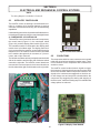
6 Electrical and Mechanical Control Systems
6.1 IntelliTec Controller ..................................................................................... 45
6.2 Contactors .................................................................................................. 45
6.3 Drive Motor ................................................................................................. 46
6.4 Capacitors .................................................................................................. 47
6.5 Gearbox ...................................................................................................... 47
6.6 Condenser Fan Motor (Air-Cooled Only) .................................................... 48
6.7 Cab Condenser Fan Motor ......................................................................... 48
6.8 Switches ..................................................................................................... 48
A. Spigot Switch .......................................................................................................48
B. Pump Pressure Switch .........................................................................................50
6.9 Temperature Control Sensor ...................................................................... 50
7 Troubleshooting
7.1 Error Codes ................................................................................................ 51
7.2 Troubleshooting .......................................................................................... 51
7.3 Servicing Tip ............................................................................................... 53
7.4 Troubleshooting Machine ........................................................................... 54
7.5 Troubleshooting Mix Pump ......................................................................... 55
8 Replacement Parts
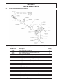
8.1 Front Door and Auger Parts ........................................................................ 57
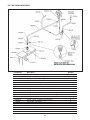
8.2 Cab Tubing Assembly ................................................................................. 58
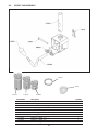
8.3 Spigot Cam Assembly ................................................................................ 59
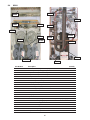
8.4 Rear of Machine ......................................................................................... 60
8.5 Right Hand Side and Header Panel ........................................................... 61
8.6 Left Hand Side and Cab Interior ................................................................. 62
8.7 Front Panel ................................................................................................. 63
8.8 Part Kits ...................................................................................................... 63
8.9 Pump Parts ................................................................................................. 64
8.10 Decals and Miscellaneous Parts ................................................................ 66
8.11 Stainless Steel Panels ................................................................................ 66
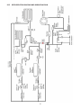
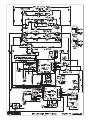
8.12 Refrigeration Diagram and Wiring Diagram ................................................ 67


1
SECTION 1
INTRODUCTION
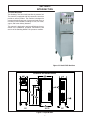
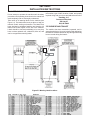
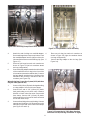
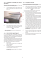
1.1 DESCRIPTION
The Stoelting F431 fl oor model machine is pressure fed.
The machine is equipped with fully automatic controls to
provide a uniform product. The machine is designed to
operate with almost any type of commercial soft-serve or
non-dairy mixes available, including ice milk, ice cream,
yogurt, and frozen dietary desserts.
This manual is designed to assist qualifi ed service per-
sonnel in the installation, operation, maintenance, and
service of the Stoelting Model F431 pressure machine.
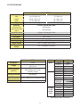
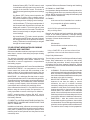
Figure 1-2 Specifi cation
Figure 1-1 Model F431 Machine

2
1.2 SPECIFICATIONS
* CutOut amps must be set on site.
Model F431
Dimensions Machine with crate
width 19-1/8’’ (48,6 cm) 27’’ (68,6 cm)
height 67-7/8’’ (172,4 cm) 78’’ (198,1 cm)
depth 37-3/4’’ (95,9 cm) 48’’ (121,9 cm)
Weight 500 lbs (226,7 kg) 650 lbs (294,8 kg)
Electrical 1 Phase, 208-240 VAC, 60Hz
circuit ampacity
24A minimum
overcurrent protection
device
30A maximum
International Option 1 Phase, 220-240 VAC, 50Hz
Compressor 11,000 Btu/hr Scroll™ Compressor
Drive Motor Two - 3/4 hp
Air Flow Air cooled units require 3” (7,6 cm) air space on both sides, 6” back.
Plumbing Fittings Water cooled units require 1/2” N.P.T. water and drain fi ttings.
Hopper Volume Two - 5.5 gallons (20,82 liters)
Freezing Cylinder
Volume
Two - 0.85 gallon (3,22 liters)
Menu Display Value
Basic CutOut * amps
Cut In T 19 °F
Cycles 20 count
Stir On 15 seconds
Stir Off 300 seconds
Advanced On Time 28 seconds
Off Time 450 seconds
Stb Time 120 minutes
Sl1DrvOn 120 seconds
Sl1DrOff 180 seconds
Sl2CutIn 32 °F
Sl2CtOut 28 °F
DftOffTm 600 seconds
Storage Refriger ** 3 Cabinet
(Left CabCutIn 38 °F
control CabCtOut 34 °F
only) Cab Off 13 minutes
Cab On 130 seconds
F431
Refrigerant R-404A
Charge
(W/C) 26 oz
(A/C) 35 oz
Suction Pressure
(at 72°F)
One Cylinder 20-22 psig
Both Cylinders 25-27 psig
Cab Only 18 psig
Discharge Pressure 240-260 psig
Cab Pressure
(only cab running)
18 psig (maintained by the bypass valve)
EPR Valve 78-80 psig

3
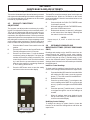
1.3 MODES OF NORMAL OPERATION
The IntelliTec control is Stoelting's newest and most ad-
vanced controller. It combines the best features of previous
controllers, with advanced sensing and troubleshooting
capabilities. Following are details of the operational modes
on the F431 with an IntelliTec control.
NOTE:
The preset amounts, times, and temperatures
listed below are references to actual settings on
the IntelliTec control. Refer to Table 1-1 on page 6
for details on each setting.
A. INITIAL STATUS
When the Main Freezer Power and Freezing Cylinder
switches are placed in the ON position, the machine will
start in the “Sleep 1 Mode". The display will read "Sleep
1 Mode". The control will eventually move into the “Sleep
2” mode if the PUSH TO FREEZE button is not pressed.
When the PUSH TO FREEZE button is pressed the control
will move to the “Serve Mode”.
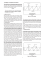
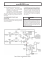
B. SERVE MODE
When the PUSH TO FREEZE button is pressed or a spigot
handle is pulled, the “Serve Mode” begins. The drive motor
starts, and after a 3 second delay, the compressor starts.
The display reads “FREEZING” on the top line and a bar
on the bottom line increases with product consistency.
A toroid on the IntelliTec control senses increasing drive
motor amperage as the product comes to consistency in
the freezing cylinder. When the control senses the product
is at 75% of consistency, the display will read "SERVE",
the amber LED will go out, and the green LED will light.
At this time, product can be served from the machine.
The drive motor and compressor will continue to run until
the toroid reads a preset value (CutOut amps). When the
toroid reads the CutOut amps on the drive motor, the
compressor turns off. After a 3 second delay, the drive
motor turns off. The product in the freezing cylinder is
now at serving temperature and consistency.
After product is at consistency, the IntelliTec control
continuously monitors refrigerant temperature through a
thermistor mounted on the side of the freezing cylinder.
When the temperature increases to a preset amount (Cut
In T), a 3-second drive motor pre-stir analyzes product
consistency. The pre-stir check is also performed each
time the spigot handle is opened. This check prevents
over-freezing of product, especially during frequent, small
volume draws. If product requires a freezing cycle, the
control will start the cycle.
During the “Serve Mode”, a stir cycle starts. This cycle is
independent of the freezing cycle and is based on preset
times (Stir On and Stir Off). The stir cycle prevents product
separation. If a freezing cycle is initiated, the timer is reset.
In addition to the "Serve Mode" freezing cycle, there is
a freezing cycle based on a preset time (DftOffTime). If
this time is attained without a freezing cycle, the control
will automatically start a freezing cycle.
The machine will remain in “Serve Mode” until the cycle
count setting is attained. The cycle count is the number
of active freezing cycles and is based on a preset value
(Cycles). Once the cycle count has been reached without
user interruption, the control will move into the "Standby
Mode".
If the PUSH TO FREEZE button is pressed or a spigot
handle is pulled, the cycle count is reset and the control
will move to the beginning of the "Serve Mode". Refer to
Figure 1-3 for a graphical representation of the "Serve
Mode".
C. STANDBY MODE
If no product has been drawn from the spigot and the
preset number of active freezing cycles is met, the control
moves into the “Standby Mode”. In "Standby Mode", the
freezing cycle is based on preset timers (On Time and Off
Time), and prevents ice crystals from building up in the
product. Because the product remains partially frozen,
it can quickly return to servable consistency when the
PUSH TO FREEZE button is pressed.
During “Standby Mode”, the stir cycle runs. This cycle is
based on preset, timed intervals (Stir On and Stir Off) and
prevents product separation.
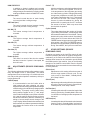
Figure 1-3 Serve Mode
Figure 1-4 Standby Mode

4
The "Standby Mode" maintains product quality during
slow times, while minimizing reactivation time. This mode
lasts for a preset time (Stb Time). Once this time has been
reached without user interruption, the control moves into
the "Sleep 1 Mode". Refer to Figure 1-4 for a graphical
representation of the "Standby Mode".
If a spigot is opened or the PUSH TO FREEZE button is
pressed, the control will move to “Serve Mode”. Product
in the front of the freezing cylinders may or may not be at
consistency. The state of the product is dependant on a
number of variables but will come to consistency quickly.
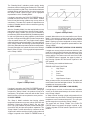
D. SLEEP 1 MODE
After the “Standby Mode” time has expired without user
interruption, the control will move into the “Sleep 1 Mode”.
During the "Sleep 1 Mode", the stir cycle is handled by
preset timers (Sl1DrvOn and Sl1DrOff), and allows product
to melt to a liquid state by using agitation cycles without
any fl ow of refrigerant. Although the product temperature
never increases above 40°F, the product thaws rapidly
which minimizes product breakdown. The control will stay
in the “Sleep 1 Mode” until sensing a preset temperature
(Sl2CutIn). When this temperature has been reached with-
out user interruption, the control will move to the "Sleep 2
Mode". Refer to Figure 1-5 for a graphical representation
of the "Sleep 1 Mode".
If a spigot is opened or the PUSH TO FREEZE button is
pressed, the control will move to “Serve Mode”. If the spigot
is opened in "Sleep 1 Mode", the product will not be at
consistency. The operator must wait until the fi rst "Serve
Mode" freezing cycle has completed to serve product.
E. SLEEP 2 MODE
The “Sleep 2 Mode” maintains the freezing cylinder
temperature between two preset values (Sl2CutIn and
Sl2CtOut). During the “Sleep 2 Mode”, the stir cycle
runs. This cycle is based on preset, timed intervals (Stir
On and Stir Off) and prevents product separation. The
"Sleep 2 Mode" is often referred to by customers as the
“night mode” and the machine will stay in this mode until
a spigot is opened or the PUSH TO FREEZE button is
pressed. When this occurs, the control will move to “Serve
Mode”. If the spigot is opened at this time, the product
will be liquid. The operator must wait until the fi rst "Serve
Mode" freezing cycle has completed to serve product.
Refer to Figure 1-6 for a graphical representation of the
"Sleep 2 Mode".
F. INTELLITEC RESTART (VERSION 3.5 OR HIGHER)
If a hard error occurs (refer the hard error list below), the
IntelliTec control will wait 5 minutes then attempt to clear
the error by restarting itself. The control will count each
restart attempt. The restart count will reset if the PUSH
TO FREEZE button is pressed, the spigot is pulled, or
the Freezing Cylinder OFF/ON switch is placed in the
OFF position.
The following are considered hard errors:
ERROR CODE MALFUNCTION
2 High Torque
3 Run Time
4 Clean
7 Drive Motor
9 High Pressure Cutout
When a restart occurs, the second line of the display will
read "Restart" and the backlight will blink. This will occur
regardless of the system mode.
G. SLEEP 3 MODE (VERSION 3.5 OR HIGHER)
If a high torque, run time, or drive motor error condition
occurs on the third restart attempt, the control will move
to the "Sleep 3 Mode".
In "Sleep 3 Mode" freezing cylinder refrigeration will run
for 4 seconds every 10 minutes. This ensures the product
temperature never increases above 40°F. The stir cycle
and the auger do not run during "Sleep 3 Mode".
The control will exit "Sleep 3 Mode" if the PUSH TO
FREEZE button is pressed, the spigot is pulled, or the
Freezing Cylinder OFF/ON switch is placed in the OFF
position.
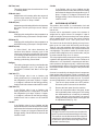
Figure 1-5 Sleep 1 Mode
Figure 1-6 Sleep 2 Mode

5
H. CLEAN MODE
When the CLEAN button is pressed on the left side, all
hopper refrigeration stops. When the CLEAN button is
pressed on the right side, only the right barrel freezing
cycle stops. In either case, the drive motor of that barrel
starts and will run for 20 minutes and a 5 minute count-
down timer is displayed. After the time has elapsed, an
optional audible alarm will sound if this accessory has been
installed. The audible alarm is a reminder for the operator
to end the "Clean Mode" when cleaning is completed.
If the machine is kept in "Clean Mode" for more than 20
minutes, the auger drive motor stops, the hopper refrig-
eration starts, and an error code (E4) is displayed on
the display panel. The error code prevents damage to
the machine that could occur during an extended clean
mode (Refer to Section 8 - Troubleshooting for details).
To clear this error, place the Freezing Cylinder Off-On
switch in the Off position and back in the On position. If
the machine is still being cleaned, pushing the CLEAN
button will reset the timer and restart the "Clean Mode".
1.4 MIX LEVEL INDICATORS
The cabinet is equipped with a capacitive sensor to moni-
tor mix level. When the mix level drops below the sensor
limit, the lower line of the display will read "Low Mix" and
the display will fl ash. To clear the "Low Mix" error, add
mix to the cabinet's mix container.
1.5 STORAGE REFRIGERATION
The IntelliTec control is programmed to handle refrigeration
of the cabinet independently from the barrel. The control
maintains cabinet temperature between two preset values
(CabCutIn and CabCtOut). If the cabinet door is opened
during a refrigeration cycle, the evaporator fan will con-
tinue to run but the refrigeration cycle will be interrupted
to prevent the evaporator coils from icing up.
Figure 1-7 Serve Mode (Sensor Failure)
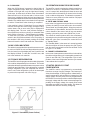
1.6 OPERATION DURING SENSOR FAILURE
The IntelliTec control is designed to allow the machine to
continue to function if a temperature sensor failure oc-
curs. If a sensor fails, the display will show the error and
the control will run the machine on timers for the freezing
cycle or cabinet refrigeration. This allows the operator to
continue to serve product from the machine until proper
servicing can be completed.
A. SERVE AND STANDBY MODE
In the event of a temperature sensor failure on a freezing
cylinder, the IntelliTec control will function in two modes,
"Serve Mode" and "Standby Mode". When the product is
at consistency in "Serve Mode", the IntelliTec control uses
a timer instead of the sensor and will not start another
freezing cycle until a preset value (DftOffTme) is met.
The control will monitor product after it is at consistency,
activating the stir cycle and counting the number of cycles.
When the cycle count is reached, the control will move
to "Standby Mode".
The "Standby Mode" is the same as in normal operation
with the exception of when the preset time (Stb Time) is
met, the control moves back into the "Serve Mode". Refer
to Figure 1-7 for details.
B. CABINET REFRIGERATION
In the event of a temperature sensor failure in the cabinet,
the cabinet refrigeration cycle is managed by preset times
(Cab On and Cab Off). This refrigeration cycle is inde-
pendent of the barrel refrigeration and the cycle restarts
if the cabinet door is opened.
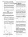
1.7 MOTOR PROFILE CUTOUT
COMPENSATION
The IntelliTec control is programmed to automatically
function at a range of supply voltages. This feature pro-
vides the advantage of having product maintained at a
specifi c temperature and consistency irrespective of the
supply voltage. A motor profi le curve is programmed on
the IntelliTec control and provides a relationship between
the supply voltage and drive motor cutout amperage. De-
pending on the supply voltage, the control varies cutout
amperage according to the motor profi le. This feature is
automatic and does not need any confi guring.

6
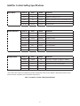
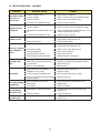
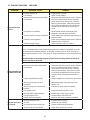
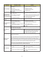
Table 1-1 IntelliTec Control Setting Specifi cations
IntelliTec Control Setting Specifi cations
Basic Menu DISPLAY Value MODE DEFINITION
CutOut * Serve Amp draw setting for cut out
Cut In T 19°F Serve Temperature setting for cut in
Cycles 20 Serve Freezing cycles before going into Standby Mode
Stir On 15 sec Serve Stir-only on time
Stir Off 300 sec Serve Stir-only off time
Advanced Menu DISPLAY Value MODE DEFINITION
On Time 28 sec Standby Freezing cycle “on” time (runs on timers only)
Off Time 450 sec Standby Freezing cycle “off” time
Stb Time 120 sec Standby Total time in mode
Sl1DrvOn 120 sec Sleep 1 Drive motor “on” timer
Sl1DrOff 180 sec Sleep 1 Drive motor “off” timer
Sl2CutIn 32°F Sleep 2 Cut in temperature
Sl2CtOut 28°F Sleep 2 Cut out temperature
DftOffTm 600 sec No Sensor Default “off” time. Used in case of sensor failure
Storage Menu DISPLAY Value MODE DEFINITION
Refriger Cabinet All Set to None, 1 Hopper, 2 Hopper, or Cabinet
CabCutIn 38°F All Refrigerated cab cut in temperature
CabCtOut 34°F All Refrigerated cab cut out temperature
Cab Off 13 min No Sensor Default “off” time. Used in case of sensor failure
Cab On 130 sec No Sensor Default “on” time. Used in case of sensor failure
* The CutOut value needs to be adjusted to product requirements. Refer to the 2183408 - Specifi cation Sheet for F431
Control located in the plastic pouch behind the header panel.

7
SECTION 2
INSTALLATION INSTRUCTIONS
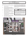
2.1 SAFETY PRECAUTIONS
Do not attempt to operate the machine until the safety
precautions and operating instructions in the manual are
read completely and are thoroughly understood.
Take notice of all warning labels on the machine (see
Figure 2-1). The labels have been put there to help you
maintain a safe working environment. The labels have
been designed to withstand washing and cleaning. All
labels must remain legible for the life of the machine.
Labels should be checked periodically to be sure they
have not been painted over, rubbed off, fallen off, and
can be recognized as warning labels.
If you are in need of replacement labels, indicate the
part number, type of label, location of label, and quantity
required along with your name and address and mail to:
Stoelting, LLC
Commercial Products
502 Hwy. 67
Kiel, WI 53042
2.2 SHIPMENT AND TRANSIT
The machine has been assembled, operated, and in-
spected at the factory. Upon arrival at the fi nal destination,
the machine must be checked for any damage which may
have occurred during fi nal transit.
Figure 2-1 Warning Label Locations

8
With the method of packaging used, the equipment should
arrive in excellent condition. THE CARRIER IS RESPON-
SIBLE FOR ALL DAMAGE IN TRANSIT, WHETHER
VISIBLE OR CONCEALED. Do not pay the freight bill
until the machine has been checked for damage. Have
the carrier note any visible damage on the freight bill. If
concealed damage and/or shortage is found later advise
the carrier within ten days and request inspection. The
customer must place claim for damage and/or shortages
in shipment with the carrier. Stoelting, LLC cannot make
any claims against the carrier.
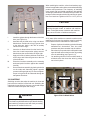
2.3 MACHINE INSTALLATION
Installation of the machine involves moving the machine
close to its permanent location, removing all crating, set-
ting in place, assembling parts, and cleaning.
A. Uncrate the machine.
B. Install the four casters. Turn the threaded end into
the machine until zero threads are showing. To
level, turn out casters no more than 1/4" maximum,
then tighten all jam nuts.
C. The machine must be placed in a solid level
position.
NOTE
Accurate leveling is necessary for correct drainage
of machine barrel and to insure correct overrun.
D. Machines with air cooled condensers require a
minimum of 3" (7,5cm) of space on all sides and
10" (25cm) at the top for proper circulation. A
minimum of 6" (15cm) side clearance is required
in high ambient conditions (>98ºF).
E. Soft serve machines with water cooled condensers
require 1/2" NPT supply and drain fi ttings.
2.4 INSTALLING PERMANENT WIRING
If permanent wiring is required by local codes, the follow-
ing procedure must be performed:
A. Refer to the nameplate on the side panel of the
machine for specifi c electrical requirements. Make
sure the power source in the building matches
the nameplate requirements.
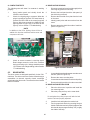
B. Remove the back panel and the junction box
cover located at the bottom of the machine.
C. Install permanent wiring according to local code.
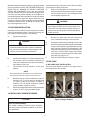
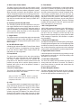
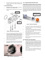
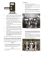
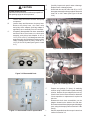
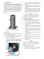
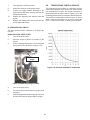
D. Check the auger shaft rotation by placing the Main
Freezer Power Switch in the ON position, placing
both Freezing Cylinder OFF/ON switches in the
ON position and pressing the CLEAN button on
each of the control panels. Auger shaft rotation
is clockwise as viewed through the clear plastic
front door (see Figure 2-2).
E. Press the CLEAN button to stop the augers.
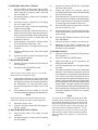
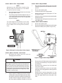
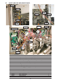
2.5 MIX PUMP
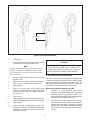
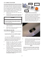
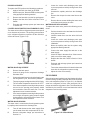
A. MIX PUMP HOSE INSTALLATION
Follow the steps below to install the mix pump hose in
the cabinet part of the machine.
Installation must be performed by a qualifi ed elec-
trician/refrigeration specialist. Incorrect installation
may cause personal injury, severe damage to the
machine and will void factory warranties.
WARNING
CAUTION
Risk of product damage
Air cooled condenser requires proper ventilation.
Failure to provide adequate ventilation will void fac-
tory warranties.
WARNING
Hazardous voltage
High voltage will shock, burn or cause death. Turn
off and lock out main power disconnect before in-
stalling wiring. Do not operate machine with cabinet
panels removed.
Figure 2-2 Auger Rotation

9
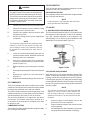
1. Turn pump on.
2. Feed one end of mix pump hose into the entering
or pickup hose side (left) of black cover.
NOTE
Feed the tube into the clamp so the natural curve of
the tube is towards the outside of the black cover.
This prevents the hose from looping around the
black cover twice.
3. Gently push the hose into the black cover until it
begins to feed.
4. Allow the hose to feed itself through the pump
until 6" (15cm) remains on the entering side.
5. Turn pump off.
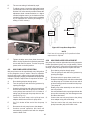
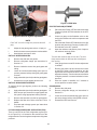
6. Connect mix pump hose to the elbow fi tting
(located on the left side of the mix line manifold)
using small hose clamp. Be careful not to twist
the mix hose.
7. Turn pump on.
8. Allow remaining 6" (15cm) of tubing to feed through
pump until hose adapter prevents further feeding.
9. Turn pump off.
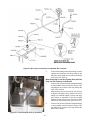
10. Connect free end of mix pump hose to 3-way Tee
as shown in Figure 2-4. When all connections are
complete the 3- way Tee must be lower than the
black pump housing.
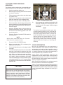
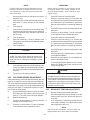
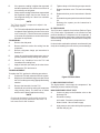
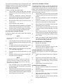
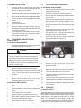
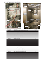
B. MIX PICKUP HOSE INSTALLATION
The F431 machine may be connected to standard mix
containers or prepacked mix bags. One, 5 gallon mix bag
may be connected to each freezing cylinder or two 2-1/2
gallon bags may be connected on each side. Follow the
instructions below that match your confi guration.
When Using One Mix Container Per Side:
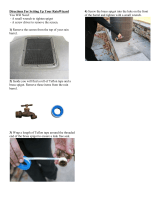
1. Connect a 2" (5cm) length of 3/8" (9,5mm)
ID plastic food grade tubing to the mix pickup
assembly. Secure with hose clamps. Then
place assembly through hole in cover and install
retaining clip (see Figure 2-4 and 2-5).
2. Connect the free end of tubing to the mix check
valve. Observe direction of check valve fl ow arrow.
Secure with hose clamp. Connect 24" (61cm)
length of 3/8" (9,5mm) ID plastic food grade tubing
to free end of check valve and secure with hose
clamp.
CAUTION
Risk of product damage
Air/mix Tee must remain below the black cover/
clamp. If Tee is above the pump, mix will drain to
the air compressor resulting in pump damage.
Figure 2-3 Mix Hose Installation
6" (15cm)

10
3. Connect elbow fi tting to free end of tubing. Connect
opposite end of elbow to 1/4" ID tan tubing on the
left side of pump head. Secure with hose clamps
(see Figure 2-3 and 2-4).
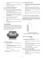
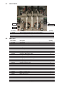
When Using Bag Connection System (BCS) with Two
Bags Per Side (optional kit #2183189):
1. Connect 3/8" (9,5mm) ID plastic food grade tubing
to a bag adapter. Secure with hose clamps. This
bag adapter will connect to the bag nearest the
front of the machine.
2. Slide the hose clip over free end of 3/8" (9,5mm)
ID plastic food grade tubing. Attach free end of
tubing to a manifold adapter. Secure with large
hose clamp or equivalent. Push the manifold
adapter into the left port of the mix inlet manifold
and secure with retaining clip. (See Figure 2-7).
3. Connect 3/8" (9,5mm) ID plastic food grade tubing
to a bag adapter. Secure with hose clamps. This
bag adapter will connect to the bag nearest the
back of the machine.
Figure 2-5 Connecting Mix Pick-up Assembly
Figure 2-4 Mix Pump Connections for Standard Mix Container

11
4. Attach free end of tubing to a manifold adapter.
Secure with large hose clamp or equivalent. Push
the manifold adapter into the right port of the mix
inlet manifold and secure with retaining clip. (See
Figure 2-7).
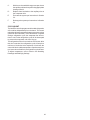
5. Place two mix bags into each mix container as
shown in Figure 2-8 (left mix container shows
two bag confi guration).
6. Connect the bag adapter attached to the left side
of the manifold to the mix bag in the front of the
mix container (nearest the cabinet door). Connect
the bag adapter attached to the right side of the
manifold to the mix bag in the back of the mix
container (see Figure 2-8).
When Using Bag Connection System (BCS) with One
Bag Per Side (optional kit):
1. Connect 3/8"(9,5mm) ID plastic food grade tubing
to a bag adapter. Secure with hose clamps.
2. Connect free end of 3/8" (9,5mm) ID plastic
food grade tubing to mix check valve. Observe
direction of check valve fl ow arrow. Secure with
hose clamp. Connect 3/8" (9,5mm) ID plastic
food grade tubing to free end of check valve and
secure with hose clamp.
3. Connect elbow fi tting to free end of tubing. Connect
opposite end of elbow to 1/4" ID tan tubing on the
left side of pump head. Secure with hose clamps
(see Figure 2-3 and 2-4).
4. Place one mix bag into each mix container as
shown in Figure 2-8 (right mix container shows
one bag confi guration).
5. Connect the bag adapter to the mix bag. (See
Figure 2-8).
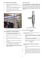
3-way Tee
Low Mix
Indicator
Adjustment
Knobs
Figure 2-6 Connecting Pump Hose to BCS Manifold
Figure 2-8 Connecting BCS Mix Bags (two bag
connection on left, one bag connection on right)
Figure 2-7 Completed BCS Hose Assembly

12
When Using Two Mix Containers or Bag Connection
Systems (BCS) on one Side (optional kit #2183189):
1. The F431 can be confi gured to operate with only
one freezing cylinder turned on. This may be done if
only one fl avor is being dispensed during slow times.
In this case, running only one freezing cylinder will
help minimize product breakdown, while reducing
mix container fi lling or mix bag replacement.
2. Connect two mix containers or two mix bags as
described above, but connect both containers to the
mix line manifold of the freezing cylinder you will be
using.
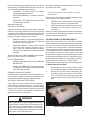
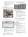
C. MIX LOW LEVEL INDICATOR ADJUSTMENT
The sensitivity of the “Mix Low” indication that displays on
the control panel can be adjusted to operator preference. If
more advanced notice of low mix is required, simply loosen
the black adjustment knobs located on the sensor brackets
at the back of the machine cabinet, and slide the bracket
upwards. If the “Mix Low” message appears while there is
still suffi cient mix in the container, slide the bracket down-
ward. Be sure to tighten the adjustment knobs after properly
positioning the sensor (see Figure 2-6).
Page is loading ...
Page is loading ...
Page is loading ...
Page is loading ...
Page is loading ...
Page is loading ...
Page is loading ...
Page is loading ...
Page is loading ...
Page is loading ...
Page is loading ...
Page is loading ...
Page is loading ...
Page is loading ...
Page is loading ...
Page is loading ...
Page is loading ...
Page is loading ...
Page is loading ...
Page is loading ...
Page is loading ...
Page is loading ...
Page is loading ...
Page is loading ...
Page is loading ...
Page is loading ...
Page is loading ...
Page is loading ...
Page is loading ...
Page is loading ...
Page is loading ...
Page is loading ...
Page is loading ...
Page is loading ...
Page is loading ...
Page is loading ...
Page is loading ...
Page is loading ...
Page is loading ...
Page is loading ...
Page is loading ...
Page is loading ...
Page is loading ...
Page is loading ...
Page is loading ...
Page is loading ...
Page is loading ...
Page is loading ...
Page is loading ...
Page is loading ...
Page is loading ...
Page is loading ...
Page is loading ...
Page is loading ...
Page is loading ...
Page is loading ...
Page is loading ...
Page is loading ...
-
 1
1
-
 2
2
-
 3
3
-
 4
4
-
 5
5
-
 6
6
-
 7
7
-
 8
8
-
 9
9
-
 10
10
-
 11
11
-
 12
12
-
 13
13
-
 14
14
-
 15
15
-
 16
16
-
 17
17
-
 18
18
-
 19
19
-
 20
20
-
 21
21
-
 22
22
-
 23
23
-
 24
24
-
 25
25
-
 26
26
-
 27
27
-
 28
28
-
 29
29
-
 30
30
-
 31
31
-
 32
32
-
 33
33
-
 34
34
-
 35
35
-
 36
36
-
 37
37
-
 38
38
-
 39
39
-
 40
40
-
 41
41
-
 42
42
-
 43
43
-
 44
44
-
 45
45
-
 46
46
-
 47
47
-
 48
48
-
 49
49
-
 50
50
-
 51
51
-
 52
52
-
 53
53
-
 54
54
-
 55
55
-
 56
56
-
 57
57
-
 58
58
-
 59
59
-
 60
60
-
 61
61
-
 62
62
-
 63
63
-
 64
64
-
 65
65
-
 66
66
-
 67
67
-
 68
68
-
 69
69
-
 70
70
-
 71
71
-
 72
72
-
 73
73
-
 74
74
-
 75
75
-
 76
76
-
 77
77
-
 78
78


Ask a question and I''ll find the answer in the document
Finding information in a document is now easier with AI
Related papers
-
Stoelting 219-02 User manual
-
-
-
-
-
-
-
-
-
Other documents
-
Broan Liquid Line Solenoid Kit #913869 Installation guide
-
Manitowoc Ice G Model Refrigeration Analysis Chart User manual
-
Scotsman EPR Setting - 17-3570-01 Operating instructions
-
-
 Rain Wizard RW40-BLK Installation guide
-
Logik LFC60W10 User manual
-
 Movincool Office Pro W20 User guide
-
 RTS Home Accents 55100001007981 Installation guide
-
Middleby 20108RSB Operating instructions
-
 EarthMinded F-RN096 Installation guide


