
INSTALLATION MANUAL
Thank you for choosing a SEA s.r.l. product. This choice will give you
the opportunity to understand that our company aims at combining
high-tech and remarkable reliability and safety, thanks to studies,
research and the accurate analysis of our customers' needs, without
undermining the simple use and installation of our products.
General features
VELA is an electro-mechanical barrier (2, 3, 4, 5 m) recommended for
the automation of access points which require a high opening/closing
speed (parking lots, motorways, airports, etc.) and frequent use
features.
The automation comes with an anti-squeezing safety system
through by pass valves for the regulation of the force which doesn't
exceed 15 kg on the beam, protecting people and things from possible
accidents. A system of hydraulic deceleration (on request) guarantees
the total control of the present inertial force in case of lack of power
supply and a release system allows the manual opening in case of
emergency.
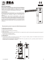
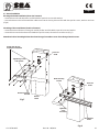
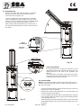
The automation system is composed of the following elements:
1 Adjustable mechanical stop
2 Manual release with DIN key
3 Galvanised steel rocker arm
4 VELA, casing cover with lock and DIN key
5 Balancing spring
6 Electronic control unit GATE 1 (code 23001120/1), a complex device which can be used to program and manage all
the operation and safety systems
7 Fixation plate out of galvanized steel
8 Hydraulique unit
9 Roller bearing
10 Cataphoresis-treated and polyester painted VELA casing, for outside, protects all included mechanical and
electronic devices from fire, flood, lightning, etc.
Predisposed for the application of photocells GHOST 40, key switch Key Plus, proximity reader Reader Prox.
Stainless steel casing available on request.
English
Sistemi Elettronici
di Apertura Porte e Cancelli
International registered trademark n. 804888
®
1010
88
66
55
44
33
22
11
77
99
Cod. 67410035 Rev 06 - 06/2010
15

Supply voltage
Force absorption
Opening/closing time
Thermoprotection
Oil quantity
Max. Beam length
Protection degree
Start condensator
Absorbed power
Working temperature
Manual release system
Usage frequency
Holding block
Slowdown
Barrier body treatment
Weight
Electronic equipment
: 230 V~ ± 5% - 50/60 Hz
: 220W
: 3,5 - 7,5 s
: 130°
: 1,8 L
: 5 m
: Ip55
: 12,5 uF
: 1,1 A
: -20°C/55°C
: yes
: 75%
: yes
: hydraulic (on request)
: Cataphoresis treated
and polyester painted
: 42 kg
: GATE 1 (cod. 23001120/1)
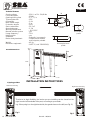
Technical features
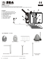
Overall dimensions:
85 (B am rotation axis0 e )
Round beam
profile
Rectangular beam
profile
English
INSTALLATION INSTRUCTIONS
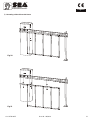
1) Spring position
Thanks to its high flexibility, the barrier you are installing can be closed on the
right-hand or left-hand side of the post, according to your needs.
e.g. if the spring is on the right-hand side, the guard closes on the left (see Fig. 2).
Left-hand mounting
Right-hand mounting
Sistemi Elettronici
di Apertura Porte e Cancelli
International registered trademark n. 804888
®
Oval beam
profile
Fig.1
Fig.2
Cod. 67410035 Rev 06 - 06/2010
16
70
25
107
76
30 30
50
1015
300
200
128
56
780

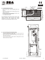
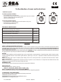
3) Post anchoring on the foundation plate
- Place the casing so that the holes on the base match the
screws located on the foundation plate.
- Make sure that the conduit for the cables goes through the large
hole of the casing base.
- Fix the casing to the foundation plate screwing with care the
delivered dice and washers
Fig.4
English
Fig.3
Concrete
Foundation plate
to be levelled
60
° ~ cla p o
pen ngm i
Conduit
500
03 0
2) Foundation plate anchoring
- Make a 500 x 500 x 300 mm (depth) hole in the
ground.
- Widen the foundation plate clamps till they reach
approx. 60° (Fig. 3).
- Fill the hole with R425 concrete and place the
foundation plate as shown in Fig. 3.
- Accurately level the plate.
* The middle hole of the plate must be used for cable
routing. Therefore, make sure that the conduit
connected to the hole complies with current
regulations, before filling the hole with concrete.
Sistemi Elettronici
di Apertura Porte e Cancelli
International registered trademark n. 804888
®
Cod. 67410035 Rev 06 - 06/2010
17

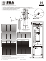
5) Mounting of the spring
-Insert the connecting rod of the spring into the hole (A or B) and
insert the dice (D) without locking them (Fig.6).
Fig.6
Note: The springs and the bracket of anchorage are supplied with the beam
Fig.5
A
B
D
Round beam
Barrier Length D. Spring Cod. kit beam
2 5 mm 11910045
2.5 5,5 mm 11910050
3 6 mm 11910055
4 6,5 mm 11910060
5 7 mm 11910065
Rectangular beam
Barrier Length D. Spring Cod. kit beam
2 5,5 mm 12710180
3 6 mm 12710185
4 7 mm 12710190
5 8 mm 12710195
Rectangular beam + skirt
Barrier Length D. Spring Cod. kit beam
3 6,5 mm 12710091
3,5 7 mm 12710092
4 8 mm 12710093
Articulated beam dx sx
Barrier Length D. Spring Cod. kit beam
3 7 mm 11902010
3 7 mm 11902020
3,5 8 mm 11902005
3,5 8 mm 11902015
Opening times
Pump Opening time
1 7,5 s
1,5 5,0 s
2 3,5 s
2 speed 2,5 s
4) Fixing of the spring on the rocker arm
- Insert with care the roller bearing (C) in the buckle (B) and execute the assemblage as Fig. 5.
- Lubricate with grease the bearing and the washers.
- Mount the resting devices as shown in Fig. 5
- At the end of installation take off the breather screws.
A
B
C
D
E
Breather screw
Before putting in function
replace the fill in cap with
the breather cap
English
Sistemi Elettronici
di Apertura Porte e Cancelli
International registered trademark n. 804888
®
Oval beam
Barrier Length D. Spring Cod. kit beam
2 5,5 16400005
2,5 6 16400008
3 6 16400008
4 7 16400015
5 8 16400026
Oval beam + skirt
Barrier Length D. Spring Cod. kit beam
2 5,5 16400005
2,5 6 16400008
3 6,5 16400010
4 8 16400026
Cod. 67410035 Rev 06 - 06/2010
18

Fig.7
Fig.8
Screw and dice for
locking the rod/beam
English
6) Beam installation
Rectangular beam installation (from 2 to 5 meters)
- Insert the beam in vertical position and fix it with the special screw and the washer.
- Insert the beam on the bracket with the rubber turned to the closing side and fix it with the special screws, washers and nuts
(Fig.8)
Mounting of the round beam (from 2 to 5 meters)
- Insert the bracket of beam anchorage in vertical position and fix it with the special screw and washer.
- Insert the beam on the bracket and fix it with the special screws, the washers and the nuts (Fig.7).
Attention: Before inserting the bracket of anchorage, insert the screws of anchorage into the same.
Tightening screw
and washer
Beam anchoring
bracket
Round
beam
Grooved
shaft
beam anchoring
bracket
Tightening
screw
and washer
Grooved
shaft
Rectangular
beam
Sistemi Elettronici
di Apertura Porte e Cancelli
International registered trademark n. 804888
®
Cod. 67410035 Rev 06 - 06/2010
19

Mounting of the oval beam
Note: For 4 and 5 m beams it is recommended to use the fork support or the flexible support.
Sistemi Elettronici
di Apertura Porte e Cancelli
International registered trademark n. 804888
®
English
Fig.9
Cod. 67410035 Rev 06 - 06/2010
20

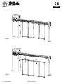
7) Mounting of the skirt on the beam
Fig.10
Fig.11
English
Sistemi Elettronici
di Apertura Porte e Cancelli
International registered trademark n. 804888
®
Cod. 67410035 Rev 06 - 06/2010
21

Sistemi Elettronici
di Apertura Porte e Cancelli
International registered trademark n. 804888
®
Fig.12
Fig.13
English
Mounting of the skirt on the oval beam
Cod. 67410035 Rev 06 - 06/2010
22

Fig. 14
Fig. 15
5
4
5
4
9) Force adjustment
If necessary the force of thrust of the beam can be
adjusted through the two calibration screws (grey and
yellow) placed on the side of the hydraulic unit
(Fig.16).
*The automation is adjusted at 15 kg force ex works
so to guarantee the anti-crush safety. We recommend
to adjust it only in case of necessity.
Fig.16
- +
English
8) Beam balancing
- Release the beam with manual release, so that it is
free to be opened and closed manually (Fig.18).
- Place the beam at approx. 45°.
- Loosen or tighten the spring stretching nut until the
spring counterbalances the weight of the 45° beam
(Fig. 14). The best balancing position is obtained when
the beam reaches the position shown in Fig. 14.
- After having obtained the balancing, lock the nuts of
the spring stretcher with the counter nut and re-block
the motor.
Spring
nutstretching
Anchoring
lock nut
10) Beam levelling
Note: this operation must be carried out only if the beam is not
perfectly horizontal (closing stage) or vertical (opening stage) at
the end of its stroke.
- Release the beam with the special manual release so that it is
free to open and close manually.
- Release the screws of the limit switch on unscrewing the nuts
on the mechanical stops (fig.15).
- Loosen or tighten the stop screws so that the beam is released
in its vertical position (opening stage) and horizontal position
(closing stage) (Fig. 15).
- After having executed the levelling lock the screws of the limit
switch tightening the nuts on the mechanical stops and re-lock
the beam.
Sistemi Elettronici
di Apertura Porte e Cancelli
International registered trademark n. 804888
®
Cod. 67410035 Rev 06 - 06/2010
23

English
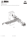
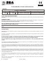
11) Electrical system
Fig. 17 sketches the electrical system that the barrier requires.
The two numbers located near the electrical cables indicate the cable number and section.
Captions:
1- GATE 1 electronic control unit
2- Transmitting photocell (Ghost 40)
3- Receiving photocell (Ghost 40)
4- Key switch (Key Plus)
5- Radio receiver
6- Flashing light (Flash)
7- Push-button station
8- Differential switch
Sistemi Elettronici
di Apertura Porte e Cancelli
International registered trademark n. 804888
®
11
22
44
55
66
77
88
2x1
2x1
2x1
4x1
3x1,5
3x1
Fig.17
33
3x1
GHOST 40 - GHOST 50
ACCESSORIES FOR VELA
* FORK SUPPORT
* FEXLIBLE SUPPORT
(ONLY BEAM)
* it is reccommended to mount with beams which are longer than 3 m.
SKIRT
ARTICULATED BEAM
KEY SWITCH
WARNING LAMP
Cod. 67410035 Rev 06 - 06/2010
24

NOTES
The electrical installation and the operation logics must comply with current regulations. Keep the power cables (motors, power
supply) separated from the control cables (push-buttons, photo-eyes, radio, etc.). Separate conduits should be used to prevent
noise issues.
Note: Use “cable clips” and/or “duct/box pipes” fitting close to the control panel box so to protect the interconnection cables
against pulling efforts.
Note: The beam is not equipped with movement inversion system in case of obstacles. To respect the laws EN 12453 and EN
12445 it is recommended to insert external disposals into it.
INTENDED USE
VELA system has been designed exclusively for the automation of barriers.
SPARE PARTS
The spare parts orders must be sent to:
SEA s.r.l. Zona Ind.le, 64020 S.ATTO Teramo Italy
SAFETY AND RESPECT FOR THE ENVIRONMENT
We recommend not to spoil the environment with product and circuit packing material.
CONFORMITY REQUIREMENTS
VELA automation system complies with the following standards:
(Machine Directive)
(Electromagnetic Compatibility Directive)
(Low Voltage Directive)
2006/42/CE
2004/108/CE
2006/95/CE
English
Sistemi Elettronici
di Apertura Porte e Cancelli
International registered trademark n. 804888
®
To the attention of users and technicians
12) Release system
To release operate as follwos
- Turn the protection cap of the lock.
- Insert the key into the same and turn it about 180° into anti-clockwise
direction until the beam is released (Fig. 18).
- Open manually the beam.
To re-lock operate as follows
- Turn the key into clockwise direction until it’s blocked. (Fig. 19).
- Extract the key in vertical position.
- Re-close the protection cap.
Fig.18 Fig.19
180°
PERIODICAL MAINTENANCE
Check the functionality of the release
Lubricate the bearing of the balance
Check the efficiency of the spring
Check the beam fixing screws and the balance and the casing
Check the integrity of the connexion cables
Check and eventually adjust the efficiency of the By pass valves
Annually
Annually
Annually
Annually
Annually
Annually
All above mentioned operations must be executed exclusively by authorized installers.
INITIAL CHECK AND PUTTING IN SERVICE
After having completed all necessary operations, for the correct installation of the product VELA, described in the present manual
and after having valued all resting risks which could arise in whatever installation is necessary to test the automation to
guarantee the max. security and in particular way to guarantee the respect of what foreseen by the law and the normatives in
force. In particular the test must be executed following the EN12445 ruel which establishes the testing methods for the testing of
the gate operators respecting the established limits by the EN 12453 law.
Cod. 67410035 Rev 06 - 06/2010
25

LONG-TERM STOP AND MAINTENANCE
The disassembly and/or stop and /or maintenance of the VELA automation system must be carried out by skilled and expert
technicians.
GUARANTEE LIMITS
VELA system is guaranteed for 24 months, starting from the date stamped on the product. The product is covered by the
guarantee provided that the damaged was not caused by inappropriate use, changes or tampering.
The warranty shall be valid only for the original buyer.
NOTE: THE MANUFACTURER SHALL NOT SHOULDER ANY RESPONSIBILITIES IN CASE OF DAMAGE CAUSED BY
INAPPROPRIATE, WRONG OR CARELESS USE.
SEA reserves the right to make all the necessary changes and modifications of the products and / or manuals without giving prior
notice
STORAGE
STORAGE TEMPERATURE
T
min
-30°C
T
max
+60°C
Humidity
min
5% without condensation
Humidity
max
90% without condensation
When being transported this product must be properly packaged and handled with care.
English
Sistemi Elettronici
di Apertura Porte e Cancelli
International registered trademark n. 804888
®
To the attention of users and technicians
ARRANGEMENTS
Read attentively the installation manual as it gives important indications concerning safety, installation, use and
maintenance.
Installation, maintenance, reparation, controls and eventual putting out of function of the product must be executed
by qualified staff only.
For the security of people it is important to follow with attention all the advises and instructions in this
manual. A wrong installation or a wrong use of the product can cause sever damages to people.
2
The max. length of the power supply cable between control unit and motors is 10m, use cables with 2,5 mm
section.
Use wirings with double insulated cables (cables with sheath) up to the immediate proximities of the terminals
especially for the power supply cable (230V ).
The control unit must not be used by people (including children) whose physical, sensory or mental ability is reduced,
or with lack of experience or knowledge, unless they are guarded or have been instructed on how to use the control
unit by a person respondsible for their safety. Children must be guarded to make sure that they don't play with the
control unit.
Foresee on the power supply net of the automation a device that assures the complete omnipolar disconnection from
the net, with a distance of opening of the contacts on each pole of at least 3mm. Those devices of disconnection have
to be foreseen on the power supply net accordingly to the rules of installation, and they have to be directly connected
to the power supply terminals.
It is necessary to keep in adequate distance (at least 2.5 mm in the air) the low tension conductors (230V ) from the
very low tension conductors (SELV) or to use a suitable sheath of at least 1 mm which supplies an additional
insulation.
Make sure that during installation the power supply and interconnection cables cannot come into contact with
pointed or sharp extremities.
~
~
Cod. 67410035 Rev 06 - 06/2010
26

Dispose of the package materials (plastics, carton, polistirene, etc.) respecting the laws in order. Keep nylon and
polistirene bags out of the reach of children.
Save these instructions for further information attaching them to the technical documents.
This product has been projected and built exclusively for the use described in this instruciton manual.
Uses not indicated in this manual could damage the product and be source of danger.
SEA declines all responsibility for improper or different use from the one for which it has been planed and described in
the present manual.
Don't install the product in explosive atmospheres.
SEA declines all responsibility for the non-observance of the good technique in the construction of closings (doors,
gates, etc.), as well as for the deformations which could occure during the use.
Remove the power supply before any intervention on the installation. Disconnect also possible battery buffers if
present.
Make sure that the earth installation has been correctly made: connect all the metallic parts of the closing (doors,
gates, etc.) and all the components of the installation provided with earth terminals.
Apply all the safety devices (photocells, sensitive edges, etc.) which are necessary to protect the area from dangers
of crushing, conveying, cutting.
SEA declines all responsibility for safety and for the correct functioning of the automation if parts of other producers
are used.
Use only original parts for any maintenance or reparation.
Do not modify the parts of the automation if not explicitly authorized by SEA.
Instruct the user of the installation on the applied command systems and how to manually open the gate in case of
emergency.
What is not explicitly contained in these instructions is not permitted.
English
Sistemi Elettronici
di Apertura Porte e Cancelli
International registered trademark n. 804888
®
To the attention of users and technicians
Cod. 67410035 Rev 06 - 06/2010
27
-
 1
1
-
 2
2
-
 3
3
-
 4
4
-
 5
5
-
 6
6
-
 7
7
-
 8
8
-
 9
9
-
 10
10
-
 11
11
-
 12
12
-
 13
13


Ask a question and I''ll find the answer in the document
Finding information in a document is now easier with AI
Related papers
-
SEA COMPACT 400 Fitting And Connection Instructions
-
-
-
-
-
-
-
-
-
Other documents
-
Kmart 43297801 User manual
-
Hasbro Robotics 80347 User manual
-
VDS BEV 2 User guide
-
Chamberlain LiftMaster BAR Owner's manual
-
Vela Person Lift Operating instructions
-
-
-
-
-
FAAC 615 Owner's manual