Page is loading ...

Tools You Will Need
• Hammer
• Tape Measure
• Level
• Stool or Short Ladder
• Shovel or Auger
• Cordless Drill
• 1/8” x 2” (3 mm x 51 mm) Steel Drill Bit
General Information
•
Read Instructions through carefully bef
ore beginning assembly.
• When assembling components, place on a non-abrasive surface
(i.e. shipping box) to avoid scratching.
• We recommend an area approx 10’x 8' (3 m x 2.4 m) for unobstructed assembling.
• You should not need to use excessive force when assembling components.
ASSEMBLY INSTRUCTI
ONS
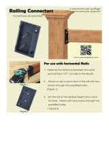
Fairfield Grande Arbor / Arch
1
www.newenglandarbors.com
www.newenglandarbors.co.uk
(Not to scale)
15
V2.4/082217
24 in
(61 cm)
32 in
(81 cm)
10.3 in (26 cm)
58.5 in
(149 cm)
82 in
(208 cm)
52.25 in
(133 cm)
80.5 in
(204 cm)
80 in
(203 cm)
88 in
(224 cm)
86.5 in
(220 cm)
107.75 in
(274 cm)
Please read through before starting assembly.
IMPORTANT: CHECK THE INSIDE OF YOUR POSTS FOR ALL
MATERIALS.
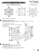
Check Box for These Contents
In the event of missing or defective parts please call our customer service dept. at 1 800 282 9346 (Mon. to Fri. 8:00 AM to 4:00 PM EST).
(UK Tel: (44) 2038 687160 (Mon. to Fri. 1:00 PM to 10:00 PM GMT).
11
10
9
8
2
4
14
1
7
6
3
12
13
5
16
1. Rafters (8)
Length 38"
(96.5 cm) - 10838
2. Pergola End Caps (20)
- 10700-1
3. Post Caps (4)
- 10824
4. Right Posts (2)
Length 84" (213 cm) - 10792
5. Left Posts (2)
Length 84" (213 cm)
- 10821
6. Post Trims (4)
- 10737-1
7. Carrying Beams (4)
Length 46 1/2" (118 cm)
- 10839
8.
Side Panel Top-Rails
(2)
Length 31 5/8“ (80 cm)
- 10822
9. Side Panel Vertical Spindles
Length 10 3/8” (26 cm) -
10795
10. Side Panel Middle Rails (2)
Length
31 5/8“
(80 cm)
-
10823
11. Side Panel Square Lattices (2)
Length 47 3/4” (121 cm) - 10793
12. Steel Stiffener Inserts (2)
- 10723-1
13. Carrying Beam Coupler (2)
- 10707-1
14. Side Panel Horizontal Bottom Rails (2)
Length 31 5/8" (80 cm)
- 10794
15.
3 in. (76 mm.)
Stainless Steel Screws
(32)
- 20007
16.
1 1/2 in. (38 mm.) Stainless Steel Screws (12)
- 20005
17.
Tube of Vinyl Glue (2) - 20000

STEP O NE
2
Assemble the Arbor Beams
1
2
3
4
3
4
Pre-drill holes on bottom and top to
accomodate for internal steel stiffener.
5
2
Insert one stee l stiffener (with ste el block facing up) into the
lowe r pocke t of the bea m past the joiner. Push until steel block
hits the internal ribbing.
Slide the beam coupler over the beam. Install the coupler so
that the four holes are facing up. Push firmly until the couple r
bottoms out on the beam.
Slide a second beam coup ler over the steel insert and into the
coupler.
Screw the coupler to the vinyl beams and steel using 1 1/2” (38
mm) screws. The bottom and top holes will need to be pre-
drilled using the stee l drill bit (not provided)
Repeat for secon d beam.
Four holes facing up
1
Predrilled holes facing up
Beam rib
is removed to
accomodate steel
stiffener
Steel block should be facing up
5
Predrilled holes facing up
Fairfield Grande Arbor / Arch

ST EP T WO
3
Assemble the Arbor Top
1
2
3
ST EP TH RE E
Assemble the Side Panels
1
2
3
4
1
2
3
1
2
3
4
Insert the la ttice into the bott om rail as shown.
Note: Bottom rail will have 7 holes on one side only
Insert the lattice assembly into the middle rail.
Note: Middle rail will have 7 holes on the bottom side and 5
holes on the top
Insert the five spindles into the top side of the middle rail.
Note: The middle rail will have 5 holes on one side onl
y, Share
the space within the middle rail for lattice and spindles.
Slide the top rail over the lattice assembly.
Repeat for other side panel.
Lay out the two carrying beams as illustrated with pre-
drilled holes facing up.
Position the eight rafters over the respective pre
drilled holes
on the carrying be ams
as illustrated.
Using the 3” (78 mm)
screws, fasten the eight rafters to the
carrying be ams.
Note: The self-augering screws will drill through the internal
rib. Keep the screw straight to drill through the internal rib.
Apply a thin bead of vinyl glue to the inside of the end cap
and install pergola end caps as illustrated.
Fairfield Grande Arbor / Arch

ST EP T WO
4
ST EP F OU R
Set out one post and complete the side panel by inserting
the s ide panel ass embly into the holes on the p ost. Push rails
until the tabs snap into place.
Repeat for the adjacent post.
Note that there is a Left and Right post. They are marked at
the top of the post.
Attach Side Panels to Posts
1
2
4
3
ST EP T WO
ST EP F IV E
Slide trim caps into place as illustrated.
If you purchased the Trim Kit (sold separately), also slide the
second set of trim caps and base moldings at this point.
Glue and insert post caps on top of posts as illustrated
Attach Trim Caps to Posts
3
4
5
5
1
2
“R”
on underside of post top.
“L”
on underside of post top.
Each side panel should have a Left and Right post.
Fairfield Grande Arbor / Arch

ST EP S IX
Move side panels to their final location and adjust the opening
width to 80 in. (203.2 cm.).
Place the pre-assembled arbor top onto the post as illustrated.
Fasten the main carrying bea ms onto the posts using two screws
per side as illustrated
.
Fasten the rafters to the posts using two screws per side as
illustrated.
Connect the Pergola Top to the Posts
1
2
5
3
3
Note: To glue the post trims in place:
1. Slide the post trim down.
2. Apply a generous amount of
vinyl glue around the post.
3. Slide the post trim back up to
desired location and allow a few
minutes to cure.
80 in.
203.2 cm.
1
2
Fairfield Grande Arbor / Arch

Move the arbor to its final location (you will need a helper).
When you have identified the location of each post, mark the
positions of the ground and then move the arbor aside.
Excavate four holes approx 33 in. (83.8 cm.) deep. The location and
e
xcavation of these four holes is the most critical step and should
be completed with care. The depth of these holes will allow the
post extension (if chosen as option) joint to be hidden 3 in. (7.6 cm.)
under the ground.
Carefully move the arbor back into position and level both
horizontal and vertically.
Backfill the holes with either gravel or cement
.
1
2
3
4
5
Arbors must be well secured to prevent tipping over from
wind load, etc.
Into Earth with Concrete Footing
(Option One)
(Assuming posts have been extended)
4
(Measurements shown are inside to inside of posts)
6
ST EP S EVEN
Install the Arbor into the Ground
You have Three Options to Complete this Step.
(All purchased separately)
OPTION ONE - If Your Arbor:
• is going to be installed with fencing or a gate
• is located in a high wind or hurricane area
• is located in ground conditions that are not level
Consider Using:
A - 4x4
Professional Post Extension Kit
(30 in./76.2 cm. long), (Kit of 4)
• Purchase from New England Arbors, www.newenglandarbors.com
• Recommended to be installed in concrete footings
• Follow instructions included with the kit
- or -
B - 4 x 4 x 3’ (91.4 cm.) Long Wood Post (4)
• Purchase separate from your local lumberyard
• Recommended to be installed in concrete footing
OPTION T WO - If Your Arbor:
• is intended to be used as a stand alone garden accent or pathway
• is located on level ground
Consider Using:
4 x 4 Aussie Augers (Kit of 4)
• Purchase from New England Arbors, www.newenglandarbors.com
• Instructions are included with the kit
OPTION TH REE - If Your Arbor:
• is going to be installed onto pre-existing concrete or wood surface
Consider Using:
4 x 4 Surface Mount Kit
• Purchase from New England Arbors, www.newenglandarbors.com
• Follow instructions included with the kit
2
80 in
203.2 cm.
24 in.
61 cm.
1
3
33 in.
83.8 cm.
10 in.
25.4 cm.
Level
Shown with
Optional 4 x 4
Post Extensions
www.neweng landarbors.com
www.newenglandarbors.co.uk
North America Toll Free Phone: 1 800 282 9346
United Kingdom Tel: (44) 2038 687160
/