MK Diamond Products MK-370 Owner's Manual & Operating Instructions
- Category
- Power tools
- Type
- Owner's Manual & Operating Instructions

MK-370 SERIES
NOTE:
For your (1) one year warranty to be effective,
complete the warranty card (including the Serial
Number and mail it in as soon as possible.
Enter the Serial Number of your new saw in the
space below. The Serial Number is located on the
left side of the blade guard.
• For your own safety read
instructions manual before operating saw
• Wear eye protection
• Use splash hood for every operation
for which it can be used
• Disconnect saw before servicing, when changing
cutting wheels, and cleaning
• Use tool only with smooth edge
cutting wheels free of openings and grooves
• Replace damaged cutting wheel before operating
TILE SAW
OWNER’S MANUAL &
OPERATING INSTRUCTIONS
SERIAL NUMBER:

MK-370 Revision 06/05, Effective Date June 17, 2005 Page 2
INTRODUCTION
We at MK Diamond want to congratulate you on selecting the MK-370 Tile Saw. We are certain that you will
be pleased with your purchase. MK Diamond takes pride in producing the finest products in the industry.
Operated correctly, your MK-370 should provide you with years of quality service. In order to help you, we
have included this manual. This owners manual contains information necessary to operate and maintain your
MK-370 safely and correctly. Please take a few minutes to familiarize yourself with the MK-370 by reading
and reviewing this manual.
If you should have questions concerning your MK-370, please feel free to call our friendly customer service
department at: 800 421-5830
Regards,
MK Diamond

MK-370 Revision 06/05, Effective Date June 17, 2005 Page 3
TABLE OF CONTENTS
Page
SAFETY: 4
Safety Messages 4
Damage Prevention Message 4
General Safety Precautions and Hazard Symbols 4
California Proposition 65 Message 6
Electrical Requirements and Grounding Instructions 7
Safety Label Locations 9
Tile Saw Specific Warnings 9
Product Specifications 10
UNPACKING, TRANSPORT, UNIVERSAL STAND, and ASSEMBLY
Unpacking 11
Contents 11
Transport 11
Universal Stand 12
Assembly 13
SETUP, ADJUSTMENT AND OPERATION
Setup 15
Adjustment and Operation 18
Cleanup 24
MAINTENANCE AND TROUBLESHOOTING
Maintenance 26
Troubleshooting 29
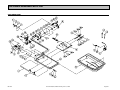
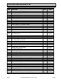
EXPLODED VIEW AND PARTS LIST
Exploded View 37
Parts List 38
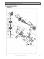
EXPLODED VIEW AND PARTS LIST of RYOBI MOTOR
Exploded View - RYOBI 33
Parts List - RYOBI 34
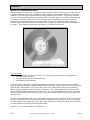
THEORY
Theory of Diamond Saws 35
ACCESSORIES
Accessories 36
ORDERING and RETURN INSTRUCTIONS
Ordering Information 37
Return Material Policy 37
Packaging Instructions 37
Authorized Service Centers 37
Manual Part No. 156760-RYOBI Revision No.02/05

MK-370 Revision 06/05, Effective Date June 17, 2005 Page 4
SAFETY
Read and follow all safety, operating and maintenance instructions. Failure to read and follow these
instructions could result in injury or death to you or others. Failure to read and follow these instructions could
also result in damage and/or reduced equipment life.
SAFETY MESSAGES:
Safety messages inform the user about potential hazards that could lead to injury, death and/or equipment
damage. Each safety message will be preceded by one of the following (3) three words that identify the
severity of the message.
Not following instructions WILL lead to DEATH or SERIOUS INJURY
Not following instructions COULD lead to DEATH or SERIOUS INJURY
Not following instructions CAN lead to injury
DAMAGE PREVENTION AND INFORMATION MESSAGES:
A Damage Prevention Message is to inform the user of important information and/or instructions that could
lead to equipment or other property damage if not followed. Information Messages convey information that
pertains to the equipment being used. Each message will be preceded by the word NOTE, as in the example
below.
NOTE:
Equipment and/or property damage may result if these instructions are not followed.
GENERAL SAFETY PRECAUTIONS AND HAZARD SYMBOLS:
In order to prevent injury, the following safety precautions and symbols should be followed at all times!
Safety Precautions:
KEEP GUARDS IN PLACE.
REMOVE ADJUSTING KEYS AND WRENCHES.
Form a habit of checking to see that keys and adjusting wrenches are removed from the power tool before it
is turned on.
KEEP WORK AREA CLEAN.
Cluttered work areas and benches invite accidents.
DO NOT USE IN DANGEROUS ENVIRONMENTS.
Do not use power tools in damp or wet locations nor expose them to rain. Always keep the work area well
lighted.
KEEP CHILDREN AWAY.
All visitors and children should be kept a safe distance from work area.
MAKE THE WORKSHOP KID PROOF.
Make the workshops kid proof by using padlocks, master switches or by removing starter keys.
DO NOT FORCE THE TOOL.
A power tool will do a job better and safer operating at the rate for which it was designed.
USE THE RIGHT TOOL.
Do not force a tool or an attachment, to do a job that it was not designed to do.
In order to prevent injury, keep guards in place and in working order at all times.

MK-370 Revision 06/05, Effective Date June 17, 2005
Page 5
SAFETY
USE THE PROPER EXTENSION CORD.
If using an extension cord make sure it is in good condition first. When using an extension cord, be sure to
use one heavy enough to carry the current your product will draw. An undersized cord will cause a drop in
line voltage that will result in a loss of power and overheating. TABLE 1, Page 8 shows the correct AWG
size to use depending on cord length and nameplate ampere rating. If in doubt, use the next heavier gage.
The smaller the gage number, the heavier the cord.
WEAR PROPER APPAREL.
Do not wear loose clothing, gloves, neckties, rings, bracelets, or other jewelry that may be caught in moving
parts. Non-slip footwear is recommended. Wear protective hair covering to contain long hair.
ALWAYS USE SAFETY GLASSES.
Safety glasses should always be worn when working around power tools. In addition, a face,
dust mask or respirator should be worn if a cutting operation is dusty. Everyday eyeglasses only
have impact resistant lenses and may not prevent eye injury-they are NOT safety glasses.
SECURE WORK.
Clamps or a vise should be used to hold work whenever practical. Keeping your hands free to operate a
power tool is safer.
DO NOT OVERREACH.
Keep proper footing and balance at all times by not overreaching.
MAINTAIN TOOLS WITH CARE.
Keep tools clean for the best and safest performance. Always follow maintenance instructions for
lubricating, and when changing accessories.
DISCONNECT TOOLS.
Power tools should always be disconnected before servicing or when changing accessories, such as blades,
bits, cutters, and the like.
REDUCE THE RISK OF UNINTENTIONAL STARTING.
Make sure the ON/OFF switch is in the OFF position before plugging in a power tool.
USE RECOMMENDED ACCESSORIES.
Consult the owner's manual for recommended accessories. Using improper accessories may increase the
risk of personal or by-stander injury.
NEVER STAND ON THE TOOL.
Serious injury could occur if a power tool is tipped, or if a cutting tool is unintentionally contacted.
CHECK FOR DAMAGED PARTS.
Before using a power tool, check for damaged parts. A guard or any other part that is damaged should be
carefully checked to determine it would operate properly and perform its intended function. Always check
moving parts for proper alignment or binding. Check for broken parts and mountings and all other conditions
that may affect the operation of the power tool. A guard, or any damaged part, should be properly repaired
or replaced.
DIRECTION OF FEED.
Always feed work into a blade or cutter against the direction of rotation. A blade or cutter should always be
installed such that rotation is in the direction of the arrow imprinted on the side of the blade or cutter.
NEVER LEAVE A TOOL RUNNING UNATTENDED – TURN POWER OFF.
Do not leave a tool until it comes to a complete stop. Always turn a power tool OFF when leaving the work
area, or, when a cut is finished.
on

MK-370 Revision 06/05, Effective Date June 17, 2005
Page 6
SAFETY
Hazard Symbols:
ELECTRICAL SHOCK
Never touch electrical wires or components while the motor is running. Exposed, frayed or worn
electrical motor wiring can be sources of electrical shock that could cause severe injury or burns.
ACCIDENTAL STARTS
Before plugging the equipment into an electrical outlet, be sure the ON/OFF switch is in the OFF
position to prevent accidental starting. Unplug the power tool before performing any service operation.
ROTATING OR MOVING PARTS
Keep hands, feet, hair, and clothing away from all moving parts to prevent injury. Never operate a
power tool with covers, shrouds, or guards removed.
DO NOT EXPOSE TO RAIN
Do not expose to rain or use in damp locations.
Sawing and drilling generates dust. Excessive airborne particles may cause irritation to eyes, skin and
respiratory tract. To avoid breathing impairment, always employ dust controls and protection suitable to the
material being sawed or drilled; See OSHA (29 CFR Part 1910.1200). Diamond Blades improperly used are
dangerous. Comply with American National Standards Institute Safety Code, B7.1 and, Occupational Safety
and Health Act covering Speed, Safety Guards, Flanges, Mounting Procedures, General Operating Rules,
Handling, Storage and General Machine Conditions.
CALIFORNIA PROPOSITION 65 MESSAGE:
Some dust created by power sanding, sawing, grinding, drilling, and other construction activities contain
chemicals known [to the State of California] to cause cancer, birth defects or other reproductive harm. Some
examples of these chemicals are:
• Lead, from lead-based paints
• Crystalline silica, from bricks and cement and other masonry products and
• Arsenic and chromium, from chemically treated lumber
For further information, consult the following sources:
http://www.osha-slc.gov/sltc/silicarystalline/index.html
http://www.oehha.org/prop65/out_of_date/6022kLstA.html
Your risk from these exposures varies depending on how often you do this type of work. To reduce your
exposure to these chemicals, work in a well-ventilated area, and work with approved safety equipment, such
as those dust masks that are specially designed to filter out microscopic particles.
ELECTRICAL REQUIREMENTS AND GROUNDING INSTRUCTIONS:
on

MK-370 Revision 06/05, Effective Date June 17, 2005
Page 7
SAFETY
In order to prevent potential electrical shock and injury, the following electrical safety precautions and symbols
should be followed at all times!
In case of a malfunction or breakdown, grounding provides a path of least resistance for electric
current to reduce the risk of electric shock. This tool is equipped with an electric cord having an
equipment-grounding conductor and a grounding plug. The plug must be plugged into a matching
outlet that is properly installed and grounded in accordance with all local codes and ordinances.
• Do not modify the plug provided – if it will not fit the outlet; have the proper outlet installed by a
qualified electrician
• Improper connections of the equipment-grounding conductor can result in a risk of electric shock.
The equipment-grounding conductor is the insulated conductor that has an outer surface that is
green, with or without yellow stripes. If repair or replacement of the electric cord or plug is
necessary, do not connect the equipment-grounding conductor to a live terminal
• Check with a qualified electrician or service personnel if the grounding instructions are not
completely understood, or if in doubt as to whether the tool is properly grounded
• Use only 3-wire extension cords that have 3-prong grounding plugs and 3-pole receptacles that
accept the tool's plug
• Repair or replace a damaged or worn cord immediately
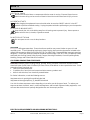
This tool is intended for use on a circuit that has an outlet that looks like the one shown in Sketch A
of Figure 1. The tool has a grounding plug that looks like the plug illustrated in Sketch A of FIGURE
1. A temporary adapter, which looks like the adapter illustrated in sketches B and C, may be used to
connect this plug to a 2-pole receptacle as shown in Sketch B, if a
properly grounded outlet is not available. The temporary adapter
should be used only until a properly grounded outlet can be
installed by a qualified electrician. The green-colored rigid ear,
lug, and the like, extending from the adapter, must be connected
to a permanent ground such as a properly grounded outlet box.
NOTE: Use of a temporary adapter is not permitted in Canada.
To reduce the risk of electrocution, keep all connections dry and off the ground.
A Ground Fault Circuit Interrupter (GFCI) should be provided on the circuit(s) or outlet(s) to be used
for the Tile Saw. Receptacles are available having built-in GFCI protections and may be used for
this measure of safety.
When using an extension cord, the GFCI should be installed closest to the power source, followed
by the extension cord and lastly, the saw.
M
eta
l
Sc
r
e
w
Cover of Grounded
Outlet Box
(
A
)
(
B
)
(
C
)
(
D
)
A
DAPTER
Grounding
Means
Grounding
Pin
Grounding
Pin
FIGURE 1

MK-370 Revision 06/05, Effective Date June 17, 2005
Page 8
SAFETY
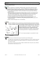
To avoid the possibility of the appliance plug or receptacle getting wet, position the saw to one side
of a wall mounted receptacle. This will prevent water from dripping onto the receptacle or plug. A
"drip loop," shown in FIGURE 2, should be arranged by the user to properly position the power cord
relative to the power source.
The "drip loop" is that part of the cord below the level of the receptacle, or
the connector, if an extension cord is used. This method of positioning the
cord prevents the travel of water along the power cord and coming in
contact with the receptacle.
If the plug or receptacle gets wet, DO NOT unplug the cord. Disconnect
the fuse or circuit breaker that supplies power to the tool. Then unplug and
examine for presence of water in the receptacle.
Use only extensions cords that are intended for outdoor use. These extension cords are identified
by a marking "Acceptable for use with outdoor appliances; store indoors while not in use." Use only
extension cords having an electrical rating not less than the rating of the product. Do not use
damaged extension cords. Examine extension cords before using and replace if damaged. Do not
abuse extension cords and do not yank on any cord to disconnect. Keep cords away from heat and
sharp edges. Always disconnect the extension cord from the receptacle before disconnection the
product form the extension cord.
To reduce the risk of electrocution, keep all connections dry and off the ground. Do not touch the
plug with wet hands.
Use of undersize extension cords result in low voltage to the motor that can result in motor burnout
and premature failure. MK Diamond warns that equipment returned to us showing signs of being run
in a low voltage condition, through the use of undersized extension cords will be repaired or replaced
totally at the customers expense. There will be no warranty claim.
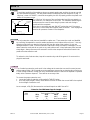
To choose the proper extension cord,
• Locate the length of extension cord needed in TABLE 1 below.
• Once the proper length is found, move down the column to obtain the correct AWG size required
for that length of extension cord.
As an example, a fifty (50) foot extension cord would require an AWG size of 16.
Extension Cord Minimum Gage for Length
Volts Total Length of Cord in Feet
120V 25 ft. 50 ft. 100 ft 150 ft.
AWG AWG AWG AWG
14 12 Not Recommended
TABLE 1
Supporting
Surface
Power
Tool
Drip Loop
Power
Cord
FIGURE 2

MK-370 Revision 06/05, Effective Date June 17, 2005
Page 9
SAFETY
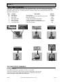
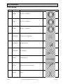
SAFETY LABEL LOCATIONS:
Safety labels are located according to Figures 1 through 6 below. The labels contain important safety
information. Please read the information contained on each safety label. These labels are considered a
permanent part of your saw. If a label comes off or becomes hard to read, contact MK Diamond or your
dealer for a replacement
Item Location Description Part No.
1A. Motor Mount Serial Number 157249-04
1B. Motor Mount Warning Read and Follow Operating Instructions 155806
2. Motor Rear Motor Specifications N/A
3 Motor Right Side Caution Use Ground Fault Interrupt 155678
4 Motor Left Side Caution Receptacle for Pump Only 154822
5 Pump Left Side Warning Connect to Grounded Receptacle N/A
6 Pump Right Side Pump Specifications N/A
TILE SAW SPECIFIC WARNINGS:
Wear eye protection.
Use splash hood for every operation for which it can be used.
Disconnect saw before servicing, when changing cutting blades, and cleaning.
Use tool only with smooth edge cutting blades free of openings and grooves.
Replace damaged cutting blade before operating.
6
5
1
B
A
23
4

MK-370 Revision 06/05, Effective Date June 17, 2005
Page 10
SAFETY
PRODUCT SPECIFICATIONS:
The MK-370 is a versatile Tile Saw. Operated and used according to this manual, the MK-370 will provide
years of dependable service.
General Description:
The MK-370 Tile Saw is engineered as a tabletop or stand mounted wet tile saw. The saw includes a powerful
115v direct drive AC motor. The saw is capable of cutting tile up to twelve (12) inches in length and one and
three quarter (1-3/4) inches thick in one pass.
Motor Specifications:
Motor specifications for the MK-370 are listed in Table 2 below.
Voltage 115 v
Motor Amperage 5.3 a
Frequency 50/60 Hz
RPM 6000 rpm
Horse Power 1-1/4 hp
Weight 30 lbs.
Table 2
Blade Capacity:
The MK-370 uses a seven (7) inch (178 mm) diameter, wet cutting continuous rim, MK Diamond blade with a
five-eighths (5/8) inch (15.875 mm) arbor.
Tile Types:
The MK-370 can cut a variety of tile types including Porcelain, Terracotta, Marble, Quarry and Slate, or almost
any other non-ferrous material.
NOTE:
The MK-370 is not designed to cut plastic or ferrous (metals) material.

MK-370 Revision 06/05, Effective Date June 17, 2005 Page 11
UNPACKING, TRANSPORT, UNIVERSAL STAND and ASSEMBLY
UNPACKING:
Your MK-370 has been shipped from the factory thoroughly inspected. Only minimal assembly is required.
Use proper lifting techniques when lifting the MK-370.
If not done, remove the MK-370, Cutting Head and accessory box from the carton.
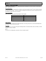
CONTENTS:
In your container, you will find one (1) MK-370 cutting surface and water pan, one (1) MK-370 cutting head,
(1) 7-inch wet cutting continuous rim diamond blade, one (1) splash guard, one (1) splash guard washer, one
(1) splash guard wing nut, one (1) electric water pump, one (1) pump discharge fitting, one (1) blade wrench
one (1) shaft wrench, one (1) owners manual, one (1) pump manual and one (1) warranty card.
MK-370 Cutting
Surface MK-370
Cutting Head Diamond Blade Splash
Guard Splash Guard
Washer
Splash Guard
Wing nut Electric
Water Pump Pump
Discharge Fitting Blade Nut
Wrench Shaft
Wrench
Owners
Manual Pump
Manual Warranty
Card
TRANSPORT:
1. The MK-370 weighs approximately fifteen (30) pounds for ease of transport.
2. Never transport the MK-370 with water in the Water Pan.
To lift the saw, grasp the Water Pan by the front and back, and then lift the entire saw.
NOTE: The Cutting Head end will be heavier than the opposite end.
Cutting Head
Lift Point Lift Point

MK-370 Revision 06/05, Effective Date June 17, 2005
Page 12
UNPACKING, TRANSPORT, UNIVERSAL STAND and ASSEMBLY
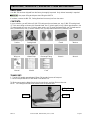
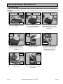
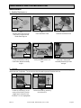
ASSEMBLY:
Follow the assembly instructions to prepare your MK-370 for operation.
1. Stand Setup:
The MK-370 weighs approximately thirty (30) pounds; follow the guidelines for transport in the
TRANSPORT section, when placing it on the stand.
2. Cutting Head Installation:
(D)
Verify the Saw is seated on the
Crossbars of the Stand
(A)
Open the Universal Stand and
place on flat surface
(B)
Orient the Saw to the Stand (C)
Seat the saw onto the Stand
Saw
Stand
Center Saw
over the
Stand Seat
Saw
Saw
Stand
Verify the Saw
is seated
Crossba
r
(A)
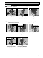
Loosen the Blade Guard
Retaining Knob
(B)
Remove the Blade Guard Wing
nut and then remove the
Blade Guard
(C)
Locate and remove the three
Cutting Head Retaining Screws
using a Phillips Screwdriver
Turn counter-
clockwise to remove
Retaining
Knob WingnutTurn counter-
clockwise to remove
Blade
Guard Retaining
Screws

MK-370 Revision 06/05, Effective Date June 17, 2005
Page 13
UNPACKING, TRANSPORT, UNIVERSAL STAND and ASSEMBLY
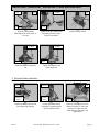
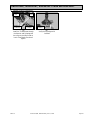
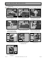
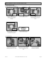
3. Diamond Blade Installation:
NOTE: When installing the Retaining Screw, do not “cross-thread" and DO NOT over tighten the screw.
(D)
Align the Cutting Head
Retaining Holes to the holes on
the Post
(E)
Install the three Cutting Head
Retaining Screws using a
Phillips Screwdriver
(F)
Install the Blade Guard
(H)
Tighten the Blade Guard
Retaining Knob
Retaining
Hole
Post
Hole
Align
Holes Turn clockwise
to tighten
Retaining
Screws
Blade
Guard
(G)
Install the Blade Guard Wing
nut
Wing Nut
Turn clockwise
to tighten Turn clockwise
to tighten
Retaining
Knob
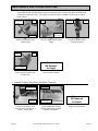
(A)
Loosen the Blade Guard Pivot
Point Retaining Wingnut
(C)
Place the Shaft Wrench on the
Motor Shaft (NOTE: the Outer
and Inner Flanges and the
Blade Nut are removed in the
photo above
(B)
Loosen the Blade Guard
Retaining Thumbscrew and
open the Blade Guard
Retaining
Wingnut
Turn counter-
clockwise to
loosen
Retaining
Thumbscrew
Turn counter-
clockwise to
loosen
Motor
Shaft
Shaft
Wrench

MK-370 Revision 06/05, Effective Date June 17, 2005
Page 14
UNPACKING, TRANSPORT, UNIVERSAL STAND and ASSEMBLY
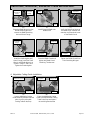
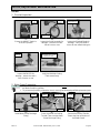
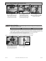
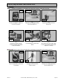
4. Adjustable Cutting Guide Installation:
(F)
Verify the Directional Arrow of
the Blade faces outward and
matches the Directional Arrow
of the Blade Guard
(G)
Install the Retaining Nut and
Outer Flange; install the Shaft
Wrench and Blade Wrench as
shown in Steps C and D and
Tighten the Retaining Nut
(E)
Install Diamond Blade onto
Blade Shaft
(I)
Tighten the Blade Guard Pivot
Point Retaining Wingnut
(H)
Close the Blade Guard and
tighten the Blade Guard
Retaining Thumbscrew
Correct Direction
of Rotation
(D)
Place the Blade Wrench on the
Blade Retaining Nut and
remove the Blade Retaining
Nut and Outer Flange
Blade
Wrench
Diamond
Blade
Blade
Shaft
Turn counter-
clockwise to
loosen
Hold
steady
Retaining Nut
and Outer
Flange
Retaining Nut
and Outer
Flange
Retaining
Thumbscrew Retaining
Wingnut
Rotate clockwise
to tighten
Turn clockwise
to tighten Rotate clockwise
to tighten
(A)
Loosen Adjustable Cutting
Guide retaining thumbscrew and
place it over the Movable
Cutting Table Ruler/Stop
(B)
Place the Adjustable Cutting
Guide onto the Movable Cutting
Table Ruler/Stop and tighten
the retaining thumbscrew
Turn clockwise
to tighten
Ruler/Stop
Adjustable
Cutting Guide
Turn counter-
clockwise to loosen
Adjustable
Cutting Guide

MK-370 Revision 06/05, Effective Date June 17, 2005
Page 15
UNPACKING, TRANSPORT, UNIVERSAL STAND and ASSEMBLY
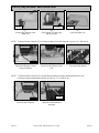
5. Splash Guard Installation:
(A)
Install the Thumbscrew through
the Washer and Splashguard
then align to the hole found on
back of the Blade Guard and
tighten
(B)
Verify the Splashguard is
installed
Splashguard
installed
Thumbscrew
and Washe
r
Turn clockwise
to tighten
Splash
Guard
Retaining
Hole

MK-370 Revision 06/05, Effective Date June 17, 2005 Page 16
SETUP, ADJUSTMENT and OPERATION
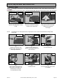
SETUP:
1. Pre-start Inspection:
Prior to beginning work, a pre-start inspection of the saw should be preformed.
2. Water Pump Preparation:
1. To prevent the possibility electrical shock, the MK-370 MUST be de-energized when preparing
the Water Pump for operation.
2. To prevent the possibility of electrical shock, use only MK Diamond qualified replacement parts
(A)
Install Water Pump Discharge
Fitting
(B)
Press the end of the Cooling
Transfer Tube onto the Water
Pump Discharge Fitting
Off
Position Inspect for
damage
Inspect for
cracks or cuts
Inspect for cracks,
de-bonding, etc.
(A)
Ensure the ON/OFF Switch is
in the OFF position
(B)
Inspect the Pump Assembly for
damage – ensure the cord is
free of cracks or cuts
(C)
Inspect the Diamond Blade for
damage – verify the blade is
correct for the material being cut
(D)
Inspect the MK-370 for
damage – ensure the cord is
free of cracks or cuts
Inspect for
damage
ON/OFF
Switch
Discharge
Fitting
Pump
(C)
Connect the Cooling Transfer
Tube to the inlet connection of
the Blade Guard
Discharge
Fitting Cooling
Transfer Tube
Press on
Cooling
Transfer
Tube
Inlet
connection
Press on
(B)
Verify the Movable Cutting
Table moves freely
Verify ease of movement
(See Maintenance section
if problems exist)

MK-370 Revision 06/05, Effective Date June 17, 2005
Page 17
SETUP, ADJUSTMENT and OPERATION
3. MK-370 Setup for Operation:
1. Before connecting the MK-370 to a power supply, be sure the voltage, cycle and phase meet the
requirements of TABLE 3 below.
VOLTAGE – 115V CYCLE – 60 Hz PHASE – 1 Phase
TABLE 3
2. If using an extension cord, make sure the length and wire gauge correspond to the requirements
listed in TABLE 1 on page 8. An extension cord that is too small in wire gauge (diameter), or too
long in length, will cause the motor to overheat and could cause premature failure.
3. Use an approved Ground Fault Circuit Interrupter (GFCI)
4. Do not cover the motor vents as this could lead to motor overheating.
NOTE: In order to avoid breaker tripping, a 20-amp circuit breaker should be used.
(A)
Plug MK-370 into the GFCI (A
GFCI should always be used
when operating the MK-370)
(C)
Plug the GFCI into the Power
source
GFCI
GFCI Plugged
Into Power
Source
(F)
Connect the Water Pump power
cord to the connection found on
the back of the motor
(E)
Fill the Water Pan with clean
water covering the Pump
Suction (this should be done
periodically during cutting)
(D)
Place the Water Pump in the
Water Pan with the Suction
down and insert the Pump
Cord to the Clip in the back
Cord Clip
Water
Pump
Fill with
clean wate
r
Cover Pump
Suction
Pump
Cord Pump
Connection

MK-370 Revision 06/05, Effective Date June 17, 2005
Page 18
SETUP, ADJUSTMENT and OPERATION
ADJUSTMENT and OPERATION:
1. Cutting Straight Edges:
DO NOT FORCE THE TOOL. It will do the job better and safer at the rate for which it was
designed.
(A)
Loosen the Adjustable Cutting
Guide retaining thumbscrew
(B)
Position the Adjustable Cutting
Guide to desired cut length
indicated inside the diamond
(C)
Tighten the retaining
thumbscrew
(D)
Place the tile against the
Ruler/Stop and Cutting Guide
(E)
Turn the motor ON (F)
Verify proper cooling flow on
both sides of the blade (See
Maintenance Section to
increase/decrease flow)
(G)
Perform the cut (H)
Turn the motor OFF when work
is complete
Off
Position
Turn Counter-
clockwise to loosen Desired Cut length
indicated here Turn clockwise
to tighten
Adjustable
Cutting Guide
Ruler/Stop
On
Position
ON/OFF
Switch Cooling Flow
Points
Hold Work
in Position
Direction
of Cut ON/OFF
Switch

MK-370 Revision 06/05, Effective Date June 17, 2005
Page 19
SETUP, ADJUSTMENT and OPERATION
2. Diagonal Cutting:
NOTE: To cut diagonal, the Dual 45º Flat Angle Guide (MK Diamond Part No. 134557-MK) should be used.
DO NOT FORCE THE TOOL. It will do the job better and safer at the rate for which it was designed.
NOTE: If Cutting the tile in two equal halves, align the tile in the V-notch of the Movable Cutting Table
Ruler/Stop.
(A)
Remove the Adjustable Cutting
Guide
(F)
Turn the motor ON
(I)
Turn the motor OFF when work
is complete
(B)
Place the Dual 45º Flat Angle
Guide on the Ruler/Stop
(D)
Position the Dual 45º Flat
Angle Guide and tighten the
retaining thumbscrew
(E)
Position the tile against the
Dual 45º Flat Angle Guide and
the Ruler/Stop
(H)
Perform the cut
Off
Position
ON/OFF
Switch
Cooling Flow
Points
(G)
Verify proper cooling flow on
both sides of the blade (See
Maintenance Section to
increase/decrease flow)
(C)
Align the Dual 45º Flat Angle
Guide for the desired
Cut Length
Ruler/Stop Ruler/Stop
Turn - clockwise to
loosen Align Guide
for Cutting
Turn counter-
clockwise to loosen Adjustable
Cutting Guide
On
Position
ON/OFF
Switch
Turn clockwise
to tighten 45º Flat
Angle Guide
Ruler/Stop
Hold Work
in position
Direction
of Cut

MK-370 Revision 06/05, Effective Date June 17, 2005
Page 20
SETUP, ADJUSTMENT and OPERATION
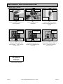
3. 45º Miter Cutting:
NOTE: To cut 45º Miters, the 45º Bullnose Miter Guide (MK Diamond Part No. 134585-MK) should be used.
DO NOT FORCE THE TOOL. It will do the job better and safer at the rate for which it was designed.
(B)
Place the 45º Bullnose Miter
Guide on the Ruler/Stop
(C)
Position the 45º Bullnose Miter
Guide and tighten the retaining
thumbscrew
(D)
Position the tile on the 45º
Bullnose Miter with the Glazed
Side down
(G)
Perform the cut
Align Guide
to Ruler/Stop Turn counter-
clockwise to loosen
Ruler/Stop
Turn clockwise
to tighten
Bull Nose
Mite
r
Hold Work
in Position
Direction
of Cut
(A)
Remove the Adjustable Cutting
Guide
Ruler/Stop
Turn counter-
clockwise to loosen Adjustable
Cutting Guide
(E)
Turn the motor ON
On
Position
ON/OFF
Switch Cooling Flow
Points
(F)
Verify proper cooling flow on
both sides of the blade (See
Maintenance Section to
increase/decrease flow)
(H)
Turn the motor OFF when work
is complete
Off
Position
ON/OFF
Switch
Page is loading ...
Page is loading ...
Page is loading ...
Page is loading ...
Page is loading ...
Page is loading ...
Page is loading ...
Page is loading ...
Page is loading ...
Page is loading ...
Page is loading ...
Page is loading ...
Page is loading ...
Page is loading ...
Page is loading ...
Page is loading ...
Page is loading ...
Page is loading ...
-
 1
1
-
 2
2
-
 3
3
-
 4
4
-
 5
5
-
 6
6
-
 7
7
-
 8
8
-
 9
9
-
 10
10
-
 11
11
-
 12
12
-
 13
13
-
 14
14
-
 15
15
-
 16
16
-
 17
17
-
 18
18
-
 19
19
-
 20
20
-
 21
21
-
 22
22
-
 23
23
-
 24
24
-
 25
25
-
 26
26
-
 27
27
-
 28
28
-
 29
29
-
 30
30
-
 31
31
-
 32
32
-
 33
33
-
 34
34
-
 35
35
-
 36
36
-
 37
37
-
 38
38


MK Diamond Products MK-370 Owner's Manual & Operating Instructions
- Category
- Power tools
- Type
- Owner's Manual & Operating Instructions
Ask a question and I''ll find the answer in the document
Finding information in a document is now easier with AI
Related papers
-
 MK Diamond Products Flat Par CWWW9 Owner's manual
-
 MK Diamond Products MK-470 Owner's manual
-
 MK Diamond Products MK-370 Owner's manual
-
 MK Diamond Products MK-370 EXP Owner's Manual & Operating Instructions
-
 MK Diamond Products MK-770 Owner's manual
-
MK Diamond Products MK-101 Owner's manual
-
 MK Diamond Products MK-377 Owner's manual
-
 MK Diamond Products MK-100 JCS Owner's manual
-
 MK Diamond Products MK-377EXP Owner's manual
-
 MK Diamond Products MK-170 SERIES User manual


Other documents
-
PEARL VX10.2XLPROR Owner's manual
-
Rubi DT-7IN MAX 120V 60HZ Owner's manual
-
Norton CTC1020XL Owner's manual
-
MK MK-377EXP Owner's manual
-
-
-
Displays2go SMMDF1 Assembly Instructions
-
MK Diamond MK-100 Owner's manual
-
 QEP 60085 User manual
-
 QEP 22500Q User manual

