Page is loading ...

Operator‘s manual
Translation of the original Operating Manual
Nr.
99+2882.EN.80V.0
Rotary Swather
EUROTOP 422 A
(Type 2882 :
Chassis-Nr: +..00001
)
EUROTOP 462 A
(Type 2883 :
Chassis-Nr: +..00001)

1900_GB-PAGE 2
Product liability, information obligation
Product liability obliges manufacturers and dealers to issue operating instructions for the machine at the point of sale and to instruct
the customer on the operation, safety and maintenance regulations governing the machine.
Confirmation is required to prove that the machine and the operating instructions have been properly handed over. For this purpose
you have received a confirmation e-mail from Pöttinger. If you have not received this mail, please contact your local dealer. Your
dealer can fill in the handover declaration online.
For the purposes of product liability law, every farmer is an entrepreneur.
In the terms of product liability law, damage to property is any damage arising due to the machine, but not to the machine, and an
excess (500 euros) exists for this liability.
Corporate damage to property within the terms of the product liability law is excluded from this liability.
Be advised!
The operating instructions must also be handed over with any subsequent machine sale or transfer and the transferee
must be instructed in the regulations stated.
Pöttinger - Trust creates Afnity - since 1871
"Quality pays for itself." Therefore we apply the highest quality standards to our products which are constantly monitored by our
in-house quality management and our management board. Because the safety, perfect function, highest quality and absolute
reliability of our machines in operation are the core competencies for which we stand.
There may be deviations between these instructions and the product as we are constantly developing our products. Therefore no
claims may be derived from the data, illustrations and descriptions. Please contact your Specialist Service Centre for any binding
information about specific features of your machine.
We would ask you to please understand that changes to the scope of supply with regard to form, equipment and technical
specifications are possible at any time.
Any form of reprint, translation or reproduction, including excerpts, requires the written approval of Pöttinger Landtechnik GmbH.
All rights according to copyright laws remain expressly reserved by Pöttinger Landtechnik GmbH.
© Pöttinger Landtechnik GmbH – 31st October 2012
Refer to PÖTPRO for additional information about your machine:
Are you looking for suitable accessories for your machine? No problem! All the information you require is here at your disposal.
Scan the QR code on the machine's type plate or look under
www.poettinger.at/poetpro
www.poettinger.at/poetpro
And if we don't have what your looking for, then your Specialist Service Centre is there for you with help and advice.

DE-1901 Dokum D Attachments
- 3 -
PÖTTINGER Landtechnik GmbH
Industriegelände 1
4710 Grieskirchen, Austria
Tel. 07248 / 600 -0
Telefax 07248 / 600-2511
Please place a cross where appropriate.
X
X
According to the product liability please check the above mentioned items.
INSTRUCTIONS FOR PRODUCT HANDOVER
Confirmation is required to prove that the machine and the operating instructions have been properly handed over. For this purpose you have
received a confirmation e-mail from Pöttinger. If you have not received this mail, please contact your local dealer. Your dealer can fill in the hand
-
over declaration online.
Machine checked according to delivery note. All attached parts removed. All safety equipment, drive shaft and operating
devices at hand.
Operation, commissioning and maintenance of the machine or device discussed and explained to the customer on the basis
of the operating instructions.
Check tyres for correct air pressure.
Check wheel nuts for tight t.
Correct PTO shaft speed indicated.
Adaptation to the tractor carried out: Three point adjustment
Cardan shaft correctly cut to length.
Test run carried out and no defects detected.
Function explanation during test run.
Swivel in transport and working position explained.
Information about optional equipment is given.
Indication of unconditional reading of the operating instructions.
EN

- 4 -
EN
1500_GB-Inhalt_2611
TABLE OF CONTENTS
Table of contents
TABLE OF CONTENTS
CE sign
......................................................................
5
Meaning of warning signs
..........................................
5
Introduction
................................................................
6
Sym
BOLS
USED
CE mark
.....................................................................
7
Safety hints:
...............................................................
7
W
ARNIN
WARNINW
g
SI
g
NS
Meaning of warning signs
..........................................
8
Position of the warning signs
.....................................
9
Position of the warning signs
...................................
10
O
VERVIEW
Overview
...................................................................
11
A
TTACHIN
ATTACHINA
g
TO
TRACTOR
General safety information
.......................................
12
Attaching to tractor
...................................................
12
Preparations for initial use
........................................
14
P
AR
k
IN
g
THE
I
m
PLE
m
ENT
Parking the implement
.............................................
15
Driving on public roads
.............................................
17
Turn manoeuvres on slopes
......................................
17
Switching to transport position
.................................
18
Change to working position
.....................................
19
General safety information
.......................................
20
Requirements for operation
....................................
20
O
PERATION
Tuning of the rotor height
.........................................
22
Hydraulic swath apron (optional)
.............................
23
Folding the deflector hoops
.....................................
23
p.t.o. speed
..............................................................
23
Fault rectification
......................................................
23
Setting the cam track
...............................................
24
gENERAL
m
AINTENANCE
Safety advice
...........................................................
25
General maintenance information
............................
25
Cleaning of machine parts
.......................................
25
Parking in the open
..................................................
25
Winter storage
..........................................................
25
Articulated shafts
.....................................................
26
Hydraulic unit
...........................................................
26
Safety advice
...........................................................
27
Maintenance and Repairs
........................................
27
Cardans
...................................................................
27
Cleaning of machine parts
.......................................
27
Winter storage
..........................................................
27
Old devices - disposal
..............................................
27
mAINTENANCE
Lubrication points
.....................................................
28
Tine arms
.................................................................
29
Rotor unit
.................................................................
30
Spring tines
..............................................................
30
Lubrication chart
......................................................
31
TOP 422 A / TOP 462 A
..........................................
32
T
ECHNICAL
DATA
Technical data
..........................................................
33
Necessary connections
............................................
33
Type plate position
...................................................
34
Type plate position
...................................................
34
Use of the swath rotor as intended
..........................
34
S
UPPLE
m
ENT
Lubricants
.................................................................
41

- 5 -
EN
1500_GB-Inhalt_2611
TABLE OF CONTENTS
CE sign
Recommendations
for work safety
All points refe
-
ring to
safety in
this manual are
indicated by this
sign.
Meaning of warning signs
The CE sign, which is affixed by the manufacturer, indicates outwardly that this machine conforms
to the engineering guideline regulations and the other relevant EU guidelines.
EU Declaration of Conformity.
By signing the EU Declaration of Conformity, the manufacturer declares that the machine being
brought into service complies with all relevant safety and health requirements.
Do not enter rotor area while driving motor is running.
Never reach into the crushing danger area as long as
parts may move.
Stay clear of swinging area of implements.
495.173

- 6 -
EN
Introduct
I
IntroductIIntroduct
on
1700_GB-Introduction
Introduction
Dear Customer
These Operating Instructions are intended to allow you
to familiarise yourself with the implement and provide
you with clear information on safe and correct handling,
care and maintenance. Thus please take the time to read
these Instructions.
These Operating Instructions comprise part of the imple
-
ment. They are to be kept at a suitable location and acces
-
sible to staff over the entire service life of the implement.
Instructions based on the national provisions regarding
protection against accidents, road traffic and environmental
protection are also to be applied additionally.
Any persons commissioned with the operation, maintenance
or transport of the implement must read and understand
these Instructions, in particular the safety information, prior
to starting work. Any warranty claims lapse on non-obser
-
vance of these Instructions.
In case you have questions related to this operation manual
or further questions about this implement, please contact
your dealer.
Care and maintenance performed in good time and scru
-
pulously according to the maintenance intervals specified
ensure operational and traffic safety as well as the reliability
of the implement.
Use only the original spare parts and accessories from
Pöttinger or accepted by Pöttinger. For those parts relia
-
bility, safety and suitability for Pöttinger machines can be
assured. Warranty claims lapse if non-approved parts are
used. The use of original parts is also recommended after
the warranty period has expired to maintain the performance
of the implement in the long term.
Product liability legislation obliges the manufacturer and
the authorised dealer to issue Instructions when selling
implements and to instruct customers in the use with refer
-
ence to the safety, operating and maintenance regulations.
Confirmation in the form of a declaration of transfer is
required to verify that the implement and Instructions have
been transferred correctly. The declaration of transfer was
attached to the implement on delivery.
Every self-employed person and farmer is an entrepreneur
within the meaning of the product liability legislation. In
accordance with the laws of product liability, entrepre
-
neurial property damages are excluded from the liability.
All damage to property within the meaning of the product
liability legislation is regarded as damage caused by the
implement but not to the implement.
These Operating Instructions are integral part of the imple
-
ment delivery scope. You should therefore hand them over to
the new owner if ownership of the implement is transferred.
Train and instruct the new owner in the regulations stated.
The Pöttinger Service-Team wishes you good luck.

- 7 -
1801_EN-Sicherheit ANSI
EN
Sym
BOLS
SymBOLSSym
u
BOLS uBOLS
SE
d
SEdSE
CE mark
The CE mark, which is affixed by the manufacturer, indicates outwardly that this machine conforms to the engineering
guideline regulations and the other relevant EU guidelines.
EU Declaration of Conformity (see Attachment)
By signing the EU Declaration of Conformity, the manufacturer declares that the machine that
is brought into service complies with all relevant fundamental safety and health requirements.
Safety hints:
These Operating Instructions contain the
following Figures:
DAN
DAN
G
ER
If you do not follow the instructions in a text section
with this marking, there is a risk
of fatal or life-
threatening injury.
threatening injury.
•
All instructions in such text sections must be
followed!
WARNIN
WARNIN
G
If you do not observe the instructions marked this
way, there is the risk of a severe injury.
•
All instructions in such text sections must be
followed!
CAUTION
CAUTION
If you do not observe the instructions marked this
way, there is the risk of an injury.
•
All instructions in such text sections must be
followed!
NOTE
If you do not observe the instructions marked this
way, there is the risk of material damage.
•
All instructions in such text sections must be
followed!
TIP
The text sections marked in this way provide you with
special recommendations and advise regarding the
economical use of the implement.
ENVIRON
M
ENT
The text sections marked in this way provide practices
and advice on environmental protection.
The features marked as (optional) are only available as
standard with specific implement versions or are only
offered for specific versions as optional equipment or are
only offered in certain countries.
Figures may deviate from your implement in detail and are
to be taken as illustrations of operating principle.
Designations such as right and left always apply as the
direction of travel unless the text or illustrations clearly
show otherwise.

- 8 -
2000_EN-Warnbilder_2111
EN
Warning signs
Meaning of warning signs
1
(1x)
Secure your right to product warranty by signing the delivery
declaration.
495,713
2
(1x)
540
540 rpm
495,310
3
(2x)
Do not enter the danger area of rotating rotors.
Only enter the
danger area after the rotos have come to a stop.
495,173
4
(4x)
Never reach into the crushing danger area as long as parts
can move there.
495.171
5
(1x)
Read the operating instructions before putting the device
into operation.
494,529
6
(1x)
494.695
Nach den er
sten Betriebsstunden
Muttern bz
w.
Schrauben nachziehen.
Resserer les vis écr
ous après les 10
premières heures de f
onctionnement.
Tighten nuts and scre
ws after the
fir
st 10 hour
s of operation.
Na de eer
ste 10 werkuren bouton en
moeren natrekken.
Retighten all screws after the first hours of operation.
494.695
7
(1x)
Read the operator's manual before carrying out maintenance
work.
495,165

- 9 -
2000_EN-Warnbilder_2111
EN
Warning signs
8
(2x)
Lifting points for lifting jacks.
495.787
9
(9x)
Grease nipple positions
494.529
Position of the warning signs
037-20-003

- 10 -
2000_EN-Warnbilder_2111
EN
Warning signs
Position of the warning signs
037-20-002
037-20-006

- 11 -
2000-GB_Overview_2882
EN
Ov
E
OvEOv
rvi
ErviE
E
w
Overview
Designations:
(1) Safety hoop
(2) Hitching device
(3)
Support stand
(4) Support stand parking position
(5) Jockey wheel
(6) Safety hoop lock
(7) Swath curtain
(8) Tine tray (for non-assembled tines)
(9) Lighting
(10) Stopcock for hydraulic swath curtain lifting
(11) Tommy screw for swath curtain gap.
2
3
4
5
7
1
9
8
11
10
6
6

- 12 -
2100_GB-Attaching_2882
EN
A
TTAC
hi
N
hiNhi
g
TO
T
r
TrT
ACTO
rACTOr
r
2.
Put support stand in park position.
1
2
3
- Adjust the support stand (1) to the required length
using the locknut (3).
- Release the locking pins (2) secured with the linchpin
and remove the locking pins.
- Move the support stand out of working position (4)
and into park position (5).
5
4
TIP
Attach the support stand horizontally in park po
-
sition. The standing area of the support stand is
pointing backwards against the direction of trravel!
- Secure support stand using locking pins (2) and
linchpin.
3.
Fit cardan shaft
NOTE
Life-threatening danger exists when cardan shaft
is installed incorrectly.
•
Always mount the wide-angle joint on the
tractor - not on the machine!
-
Before initial use, you must check and if necessary
adjust the cardan shaft length (see also chapter
"Setting of cardan shaft" in Annex B.
General safety information
DAN
DAN
G
ER
Risk of death - in the event of unpredictable
movements of tractor or machine
•
Park the machine only on firm, level ground.
•
Secure the tractor against unintentional
rolling.
•
Turn the engine off.
•
Remove the key.
•
Secure the machine against tipping using
supports.
Attaching to tractor
1.
Attach the device on tractor tool bar.
TIP
Requirements:
-The tool bar must be rotatable (A-B)
-
The holes in the tool bar must have a minimum
diameter of 30 mm.
-
The left and right lifting struts (4) must be the
same length.
- Remove locking pins (1) secured with a linch pin from
the hitching device.
- Attach the hitching device to the tollbar using locking
pins.
- Secure locking pins (1) on the hitching device using
the linchpin (2).
1
2
-
Fasten the hydraulic lower link (5), so as the
implement cannot swivel out to the side.

- 13 -
2100_GB-Attaching_2882
EN
Att
A
AttAAtt
ching to tr
A
ching to trAching to tr
ctor
TIP
It is generally simpler to attach the cardan shaft first
on the machine side and then on the tractor side!
4.
Set the rear power lift at the right height (H).
- Pay attention to have a sufficient distance to the cardan
shaft (X), especially if you drive over ground tops!
5.
Connect the tractor hydraulic lines.
A
A
E
E
TD 26/92/16
s
h
0
ST
TD 26/92/16
-
Stop cock closed (position A).
-
Connect tractor hydraulic line.
-Open stopcock (position E).
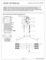
6.
M
ake electrical connections
Lighting
-
Connect 7-pin plug to tractor (E3)
-
Check that the lighting functions on the machine
7.
Lower the implement
-
Operate the single acting control valve (ST).
The implement lowers slowly to reach the ground.
8.
Adjust the play of the drawbar.
Adjust the play of the drawbar depending on whether
or not a depth wheel has been mounted.
TIP
Requirements:
- Couple the machine to the tractor and move to
the working position (see steps 1-6).
Set distance X1 using the threaded spindle
- Swivel the lever (H) upwards (90°).
- Set distance using the threaded spindle
Without jockey wheel:
X1 = 0 mm (threaded spindle at lock - no play)
With jockey wheel:
X1 = 30 - 50 mm.

- 14 -
2100_GB-Attaching_2882
EN
Att
A
AttAAtt
ching to tr
A
ching to trAching to tr
ctor
Preparations for initial use
Important!
1.
Working position means that the device has been lowered
and the rotor tines end within a raking range of approx.
2 cm above the ground (A1). See "Setting the rotor
height", "Operation" chapter.
010-04-17
A1
2.
The distance (X) between the PTO shaft and the tool bar
must have at least 120 mm in working position (standard
measure). Observe the distance "X" particularly when
driving over ground tops!
3.
The position of the rotor tines (A1) should be somewhat
parallel to the ground; less inclination to the front is
permitted.
4. Set the correct distance (X1) with the help of the
threaded spindle.
For the machines with contact wheel
(optional
equipment)"
you need to set a pivoting range of the
drawbar for a good floor adjustment of the circular tines
(A1) on uneven surfaces.
- swivel the lever (H) downwards (0°) to secure the
threaded spindle against twisting.
9.
Towing rope (option)
TIP
The towing rope is needed only with the option “hydraulic
swath apron”.
-
Lay the rope (S) into the tractor cab.

- 15 -
2100_GB-Parking_2882
EN
P
A
PAP
rki
N
rkiNrki
g
T
h
ThT
E
im
E imE
PLE
imPLE im
m
PLEmPLE
ENT
mENTm
Parking the implement
The machine can be parked both in the working position
and in the transport position.
W
W
ARNIN
WARNIN W
G
Life-threatening danger exists if another person starts
up the tractor and drives away or actuates the control
lever of the hydraulic system while you are engaged
in maintenance.
•
Before carrying out maintenance and repair
work, switch off the engine. remove the key
and engage the steering lock.
WARNIN
WARNIN
G
Life-threatening danger exists - if the tractor or device
moves unexpectedly
•
Park the tractor/wagon combination only on
solid, level ground.
•
Protect the tractor and machine against
unintentional rolling.
(Wheel chocks)
•
Secure the machine against tipping using
supports.
•
Turn the engine off.
•
Remove the key.
1.
M
ove the support stand into working position
WARNIN
WARNIN
G
Risk of injury resulting in death or other serious
injury if the unit is tipped over.
•
Check the position of the locking bolt on
the support stand.
1
2
3
- Release the locking pins (2) secured with the linchpin
and pull out of the opening.
- Dismantle the support stand (1) from park position and
move to working position
- Secure support stand using locking pins (2) and linchpin.
- Adjust the support stand (1) to the required height using
the locknut (3).
2.
Remove cardan shaft
CAUTION
CAUTION
Risk of injury by crushing the fingers.
•
Take care to protect your fingers when
removing the cardan shaft.
-
Pull off cardan shaft (GW) and place on support.
The safety chain must not be used to suspend the
cardan shaft.
3.
Uncouple the hydraulic lines
- Set the control unit to float position to depressurize the
hydraulic lines.
A
A
E
E
TD 26/92/16
s
h
0
ST
-
Uncouple hydraulic lines (DW) from tractor.
4.
Disconnect electro-cable (EL) from tractor
5.
Remove rope from tractor cabin if necessary
6.
Secure machine with wheel chock against
rolling away.
7.
Unhitch unit from tractor.
CAUTION
CAUTION
Risk of injury by crushing the fingers.
•
Pay attention to the toolbar when uncou
-
pling.
- Release the security bolts (1) secured with the linchpin
and pull out of the opening.

- 16 -
2100_GB-Parking_2882
EN
Parking the machine
1
2
- Drive the tractor away from the device
- Replace the security bolts (1) in the openings in the
coupling equipment and secure with the linchpin (2).

- 17 -
2100_DE-Working / transport position_2882
EN
Working and transport position
Driving on public roads
•
Observe
the
statutory
legislation
of
your
country/state.
•
Drive
on
public
roads
only
as
described
in
the
chapter
"Transport position".
•
Close all hydraulic circuits (A)
0
•
Protection
devices
must
be
in
proper
condition.
•
Before
travelling
bring
all
swivelling
parts
into
their
correct
positions and secure against dangerous changes to
position.
•
Check
that
lighting
functions
before
travelling.
•
Important
information
can
also
be
found
in
the
Supplement included in these operating instructions.
Hydraulic lower link
•
Secure
the
hydraulic
lower
link
(U)
so
that
implement
cannot swing out sideways.
Turn manoeuvres on slopes
WARNIN
WARNIN
G
Risk of injury resulting in death or other serious injury
from tilting the tractor/trailer unit when driving round
bends on a slope.
The tractor's driving characteristics are influenced by
the weight of the rotor unit This can lead to hazardous
situations on slopes (tipping, slipping, material breakage,
etc.).
Danger of tipping exists in particular:
1.
if the rotors are hydraulically raised.
2.
when travelling through curves with raised rotor units.
•
Reduce speed when taking bends on a
slope
•
It is better to travel in reverse on a slope
than to carry out a risky turning manoeuvre.

- 18 -
2100_DE-Working / transport position_2882
EN
Working and transport position
Switching to transport position
DAN
DAN
G
ER
Danger to life due to moving, rolling, tipping or
rotating parts.
Only carry out adjustments when the machine
•
has been parked securely and steadfastly
on level, firm ground.
•
the tractor engine is turned off and the pto
shaft is at a standstill.
•
the tractor's ignition key has been removed.
1.
Active control valve (ST) to lower the machine to the
ground (T1)
2.
Push trap sheet (9) in completely and secure with Tommy
screw (K).
3.
Swivel all deflector hoops (10) up
-the locking bolts engage automatically when the safety
bar is in the final position.
4.
Remove the side tine carriers and pin to mounting frame
(pos. 1).
1
(pos. 1).
DAN
DAN
G
ER
Life-threatening danger through rotating rotors
•
If you have not disassembled all tine car
-
riers, you must secure the rotor with a fork
(G) against twisting.
G
5.
The anti-rotation lock (G) is assembled on the right
safety bar. It is pivoted in the tine arm shaft when the
safety bar is swivelled up to prevent the rotor from
turning during the transport run.
6.
Activate the single-action control valve (ST) to swivel
the machine up to the transport position (T1).
7.
Close shut-off valves (pos. A)
For safety's sake: Only travel on public roads with shut-
off valves closed!

- 19 -
2100_DE-Working / transport position_2882
EN
Working and transport position
Change to working position
1.
Open stopcock (Pos. E)
2 Set the single-acting control valve (ST) at "Lower" to
swivel the rotor units down to the ground.
3.
Swivel left and right deflector hoops (6) out
- Release the lock by pulling the knob (A)
A
-
Locking takes place automatically in the final position.

- 20 -
2000_GB_Operation 2882
EN
Operati
O
n
General safety information
DAN
DAN
G
ER
Life-threatening danger exists through rotating rotors
and folding arms
On;y switch the PTO on if...
•
the machine is in working position.
•
all safety equipment (coverings, protective
aprons, casings, etc.) and tines are attached
to the device.
•
the safety equipment is operational and in
the safety position.
•
Before switching on the drive motor, make
sure that the working area is free and that
no one is in the danger zone.
495.173
DAN
DAN
G
ER
Life-threatening danger exists through rotating rotors
and folding arms
•
Turn the rake off before leaving the cabin.
•
Switch off engine and remove ignition key
prior to any adjustment, maintenance or
repair work.
•
Only carry out work in the danger area when
the PTO shaft is uncoupled.
•
Do not enter the danger area whilst the
rotors are in motion.
WARNIN
WARNIN
G
Life-threatening danger exists - if the tractor or device
moves unexpectedly
•
Park the tractor/wagon combination only on
solid, level ground.
•
Protect the tractor and machine against
unintentional rolling. (Handbrake/wheel
chocks)
•
Secure the machine against tipping using
supports.
•
Separate the single-action control unit by
closing the ball valve on the single-action
line.
•
Make sure that the support foot is locked
when activating the latter. The locking bolts
must jut out from the opening.
WARNIN
WARNIN
G
Risk of serious injury due to thrown material and
stones
•
Ensure that nobody is near the rake during
operation.
•
Stop work as soon as anybody enters the
danger zone.
•
Ensure that nobody is in the danger area
before starting the rake.
Requirements for operation
1.
Assemble tine carriers on the rotor.
CAUTION
CAUTION
Risk of injury through ejected tine rotor
•
Observe the direction of rotation of the
tines and the spring pins when reattach
-
ing the tines. The spring pin must close in
the rotation direction.
•
Check the spring cotter pins for damage,
deformation, and that spring clamps are
functioning.
-Fix all tine carriers onto rotor arms and secure with
linch pin.
/