Maxtor 1925 User manual
- Category
- Internal hard drives
- Type
- User manual
This manual is also suitable for

Quickview 40 20/30/40GB AT
Product Manual
May 24, 2005
Part Number: 000001925

May 24, 2005 Maxtor Corporation. All rights reserved. Printed in U.S.A.This publication
could include technical inaccuracies or typographical errors. Changes are periodically made
to the information herein – which will be incorporated in revised editions of the publication. Maxtor may
make changes or improvements in the product(s) described in this publication at any time and without
notice.
UL/CSA/VDE/TUV/RoHS
UL standard 1954 recognition granted under File No. E78016
CSA standard C22.2-950 certification granted under File No. LR49896
TUV Rheinland EN 60 950
Tested to FCC Rules for Radiated and Conducted Emissions, Part 15, Sub Part J, for Class-B Equipment.
Quickview 40 model numbers 6K020/030/040L0 meet the EU directive for the Restriction and Use of
Hazardous Substances (RoHS), 2002/95/EC of the European Parliament and the council of 27 January,
2003.
PATENTS
These products are covered by or licensed under one or more of the following U.S. Patents:
4,419,701; 4, 538,193 4,625,109; 4,639,798; 4,647,769; 4,647,997; 4,661,696; 4,669,004; 4,675,652;
4,703,176; 4,730,321; 4,772,974; 4,783,705; 4,819,153; 4,882,671; 4,920,442; 4,920,434; 4,982,296;
5,005,089; 5,027,241; 5,031,061; 5,084,791; 5,119,254; 5,160,865; 5,170,229; 5,177,771; Other U.S. and
Foreign Patents Pending.
Maxtor
®
, MaxFax
®
are registered trademarks of Maxtor Corporation, registered in the U.S.A. and other
countries. Quickview 40, AutoTransfer, AutoRead, AutoWrite, DisCache, DiskWare, Defect Free Inter-
face, and WriteCache are trademarks of Maxtor Corporation. All other brand names or trademarks are the
property of their manufacturers.

Maxtor reserves the right to make changes and improvements to its products, without incurring any obliga-
tion to incorporate such changes or improvements into units previously sold or shipped.
This product or document is protected by copyright and distributed under licences restricting its use, copy-
ing, distributing, and decompilation. No part of this product or document may be reproduced in any form
by any means without prior written authorization of Maxtor and its licensors, if any.
RESTRICTED RIGHTS LEGEND: Use, duplication, or disclosure by the government is subject to
restrictions as set forth in subparagraphs (c)(1)(ii) of the Rights in Technical Data and Computer Software
clause at DFARS 252.227-7013 and FAR 52.227-19.
THIS PUBLICATION IS PROVIDED “AS IS” WITHOUT WARRANTY OF ANY KIND, EITHER
EXPRESS OR IMPLIED, INCLUDING, BUT NOT LIMITED TO, THE IMPLIED WARRANTIES
OF MERCHANTABILITY, FITNESS FOR A PARTIULAR PURPOSE, OR NON-INFRINGE-
MENT.
You can download Maxtor publications directly from Maxtor at, www.maxtor.com
Part Number: 000001925
Before You Begin: Thank you for your interest in Maxtor hard disk drives. This manual provides technical
information for OEM engineers and systems integrators regarding the installation and use of Maxtor hard
drives. Drive repair should be performed only at an authorized repair center. For repair information, contact
the Maxtor Product Support Center at 1-800-2MAXTOR.
CAUTION: Maxtor hard drives are precision products. Failure to follow these precautions and guidelines
outlined here may lead to product failure, damage and invalidation of all warranties.
1 BEFORE unpacking or handling a drive, take all proper electrostatic discharge (ESD) precau-
tions, including personnel and equipment grounding. Stand-alone drives are sensitive to
1 electrostatic discharge (ESD) damage.
2 BEFORE removing drives from their packing material, allow them to reach room temperature.
3 During handling, NEVER drop, jar, or bump a drive.
4 Once a drive is removed from the Maxtor shipping container, IMMEDIATELY secure the
drive through its mounting holes within a chassis. Otherwise, store the drive on a padded,
grounded, antistatic surface.
5 NEVER switch DC power onto the drive by plugging an electrically live DC source cable into
the drive's connector. NEVER connect a live bus to the drive's interface connector.
6 ELECTRICAL GROUNDING - For proper operation, the drive must be securely fastened to
a device bay that provides a suitable electrical ground to the drive baseplate.

Please do not remove or cover up Maxtor factory-installed drive labels. They contain information required
should the drive ever need repair.Thank you for your interest in Maxtor hard disk drives. This manual pro-
vides technical information for OEM engineers and systems integrators regarding the installation and use of
Maxtor hard drives. Drive repair should be performed only at an authorized repair center. For repair infor-
mation, contact the Maxtor Customer Service Center at 800-2MAXTOR or 1-303-678-2015.
Corporate Headquarters:
500 McCarthy Blvd.
Milpitas, California 95035
Tel: 408-894-5000
Fax: 408-362-4740

Quickview 40 20/30/40GB AT i
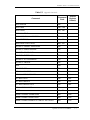
Table of Content
Chapter 1
INTRODUCTION
1.1 MAXTOR CORPORATION................................................................. 1-1
1.2 AUDIENCE ..................................................................................... 1-1
1.3 MANUAL ORGANIZATION.................................................................1-2
1.4 TERMINOLOGY AND CONVENTIONS................................................. 1-2
1.5 REFERENCES.................................................................................. 1-4
Chapter 2
PRODUCT DESCRIPTION
2.1 PRODUCT DESCRIPTION.................................................................. 2-1
2.2 KEY FEATURES .............................................................................. 2-1
2.3 REGULATORY COMPLIANCE STANDARDS ........................................ 2-3
2.4 HARDWARE REQUIREMENTS ........................................................... 2-3
Chapter 3
PRODUCT SPECIFICATIONS
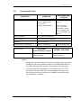
3.1 MODELS AND CAPACITIES.............................................................. 3-1
3.2 DRIVE CONFIGURATION .................................................................. 3-1
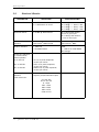
3.3 PERFORMANCE SPECIFICATIONS ..................................................... 3-2
3.4 PHYSICAL DIMENSIONS .................................................................. 3-2
3.5 POWER REQUIREMENTS.................................................................. 3-3
3.6 POWER MODE DEFINITIONS ............................................................ 3-3
3.7 EPA ENERGY STAR COMPLIANCE .................................................... 3-3
3.8 ENVIRONMENTAL LIMITS ................................................................ 3-4
3.9 SHOCK AND VIBRATION ................................................................. 3-5
3.10 RELIABILITY SPECIFICATIONS......................................................... 3-6
3.11 EMC/EMI ...................................................................................... 3-7
3.11.1 RADIATED ELECTROMAGNETIC FIELD EMISSIONS - EMC COMPLI-
ANCE......................................................................................3-7
3.11.2 CANADIAN EMISSIONS STATEMENT .......................................3-7
3.12 SAFETY REGULATORY COMPLIANCE .............................................. 3-7
3.13 RoHS COMPLIANCE ........................................................................3-7

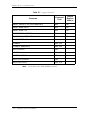
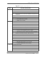
Table of Contents
ii Quickview 40 20/30/40GB AT
Chapter 4
INSTALLATION
4.1 SPACE REQUIREMENTS................................................................... 4-1
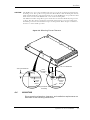
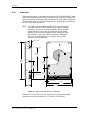
4.2 UNPACKING INSTRUCTIONS............................................................ 4-2
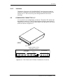
4.3 HARDWARE OPTIONS ..................................................................... 4-5
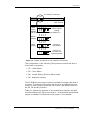
4.3.1 CABLE SELECT (CS) JUMPER ....................................................4-6
4.3.2 DRIVE SELECT (DS) JUMPER ....................................................4-7
4.3.3 MASTER JUMPER CONFIGURATION ..........................................4-7
4.3.4 JUMPER PARKING (PK) POSITION .............................................4-7
4.3.5 ALTERNATE CAPACITY (AC) ....................................................4-8
4.4 ATA BUS ADAPTER ........................................................................ 4-9
4.4.1 40-PIN ATA BUS CONNECTOR ..................................................4-9
4.4.2 ADAPTER BOARD ....................................................................4-9
4.5 MOUNTING .................................................................................. 4-10
4.5.1 ORIENTATION .......................................................................4-10
4.5.2 CLEARANCE .........................................................................4-12
4.5.3 VENTILATION ........................................................................4-12
4.6 COMBINATION CONNECTOR (J1)................................................... 4-12
4.6.1 DC POWER (J1, SECTION A) ...................................................4-13
4.6.2 EXTERNAL DRIVE ACTIVITY LED .............................................4-13
4.6.3 ATA BUS INTERFACE CONNECTOR (J1, SECTION C) ................4-13
4.7 FOR SYSTEMS WITH A MOTHERBOARD ATA ADAPTER................... 4-14
4.8 FOR SYSTEMS WITH AN ATA ADAPTER BOARD ............................. 4-14
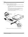
4.8.1 ADAPTER BOARD INSTALLATION ...........................................4-14
4.9 TECHNIQUES IN DRIVE CONFIGURATION........................................ 4-17
4.9.1 THE 528-MEGABYTES BARRIER ..............................................4-17
4.9.2 THE 8.4-GIGABYTES BARRIER ................................................4-17
4.9.3 OPERATING SYSTEM LIMITATIONS .........................................4-18
4.10 SYSTEM STARTUP AND OPERATION ............................................ 4-18
Chapter 5
ATA BUS INTERFACE AND ATA COMMANDS
5.1 INTRODUCTION.............................................................................. 5-1
5.2 MECHANICAL INTERFACE ............................................................... 5-1
5.2.1 SIGNAL CABLE AND CONNECTOR .............................................5-1
5.3 ELECTRICAL INTERFACE ................................................................. 5-1
5.3.1 ATA BUS INTERFACE ...............................................................5-1
5.4 REGISTER ADDRESS DECODING ...................................................... 5-2
5.5 COMMAND INTERFACE................................................................... 5-2
5.5.1 GENERAL FEATURE SET ...........................................................5-2
5.5.2 SUPPORTED COMMANDS ........................................................5-2

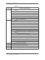
Table of Contents
Quickview 40 20/30/40GB AT iii
Chapter 6
SERVICE AND SUPPORT
6.1 PRODUCT SUPPORT/TECHNICAL ASSISTANCE/CUSTOMER SERVICE. 6-1
Glossary................................................................................................G-1

Quickview 40 20/30/40GB AT iii
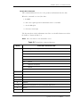
List of Figures
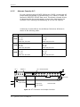
Figure 4-1 Mechanical Dimensions...........................................................4-1
Figure 4-2 Single-Pack Shipping Container ..............................................4-3
Figure 4-3 25-Pack Shipping Container ...................................................4-4
Figure 4-4 Jumper Locations on the Interface Connector ..........................4-5
Figure 4-5 AT Connector and Jumper Location ........................................4-8
Figure 4-6 Mounting Screw Clearance.....................................................4-9
Figure 4-7 Mounting Dimensions .........................................................4-10
Figure 4-8 J1 DC Power and ATA Bus Combination Connector ................4-11
Figure 4-9 Drive Power Supply and ATA Bus Interface Cables ................. 4-14
Figure 4-10 Completing the Drive Installation ..........................................4-15

Quickview 40 20/30/40GB AT iv
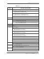
List of Tables
Table 4-1 AT Jumper Option.........................................................................4-6
Table 4-2 J1 Power Connector, Section A......................................................4-12
Table 4-3 Logical Addressing Form.................................................................4-19
Table 5-1 Supported Commands.................................................................... 5-2
Table 5-2 Identify Drive Command Parameters.....................................................5-
5

Quickview 40 20/30/40GB AT 1-1
Chapter 1
Introduction
1.1 Maxtor Corporation
Maxtor corporation is one of the world’s largest suppliers of hard disk
drive products-products that help store the digital world for millions of
users. Maxtor products serve a range of markets, including personal and
entertainment, small office/home office, mid-sized business and
enterprise
Products
Maxtor storage products include drives and accessories for PC’s,
workstations, RAID products, enterprise applications, enterprise servers,
high-end systems, consumer electronics and personal storage.
Support
Maxtor provides a variety of consumer support options, all designed to
make sure the user gets fast, helpful, accurate information to help resolve
any difficulties. These options include a broad, searchable knowledge
base of FAQ’s, product manuals, installation guides, information on
previously resolved problems, software downloads, and contact by
phone or E-mail with a support person. For more information, visit
www.maxtor.com/en/support.
1.2 Audience
The Quickview 40 20/30/40GB AT product manual is intended for
several audiences. These audiences include: the end user, installer,
developer, consumer electronics original equipment manufacturer
(CE,OEM), and distributor. The manual provides information about
installation, principles of operation, interface command implementation,
and maintenance.

Introduction
1-2 Quickview 40 20/30/40GB AT
1.3 MANUAL ORGANIZATION
This manual is organized into the following chapters:
• Chapter 1 – Introduction
• Chapter 2 – Product Description
• Chapter 3 – Product Specifications
• Chapter 4 – Installation
• Chapter 5 – ATA Bus Interface and ATA Commands
• Chapter 6 – Service and Support
• Glossary
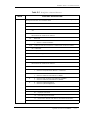
1.4 TERMINOLOGY AND CONVENTIONS
In the Glossary at the back of this manual, you can find definitions for many of the
terms used in this manual. In addition, the following abbreviations are used in this
manual:
• ASIC application-specific integrated circuit
• ATA advanced technology attachment
• bpi bits per inch
• DA Double Amplitude (represents ph-pk shaker displacement)
• dB decibels
• dBA decibels, A weighted
• DPS Data Protection System
• SPS Shock Protection System
• ECC error correcting code
• Kfci thousands of flux changes per inch
•Hz hertz
•KB kilobytes
• LSB least significant bit
• mA milliamperes
• MB megabytes (1 MB = 1,000,000 bytes when referring to disk
transfer rates or storage capacities and 1,048,576 bytes in all
other cases)
• Mb/s megabits per second

Introduction
Quickview 40 20/30/40GB AT 1-3
• MB/s megabytes per second
• MHz megahertz
• ms milliseconds
• MSB most significant bit
• mV millivolts
• ns nanoseconds
• tpi tracks per inch
• µs microseconds
•V volts
The typographical and naming conventions used in this manual are listed below.
Conventions that are unique to a specific table appear in the notes that follow that
table.
Typographical Conventions:
• Names of Bits: Bit names are presented in initial capitals. An example
is the Host Software Reset bit.
• Commands: Interface commands are listed in all capitals. An example
is WRITE LONG.
• Register Names: Registers are given in this manual with initial capitals.
An example is the Alternate Status Register.
• Parameters: Parameters are given as initial capitals when spelled out,
and are given as all capitals when abbreviated. Examples are Prefetch
Enable (PE), and Cache Enable (CE).
• Hexadecimal Notation: The hexadecimal notation is given in 9-point
subscript form. An example is 30
H
.
• Signal Negation: A signal name that is defined as active low is listed
with a minus sign following the signal. An example is RD–.
• Messages: A message that is sent from the drive to the host is listed in
all capitals. An example is ILLEGAL COMMAND.
Naming Conventions:
• Host: In general, the system in which the drive resides is referred to as
the host.
• Computer Voice: This refers to items you type at the computer
keyboard. These items are listed in 10-point, all capitals, Courier font.
An example is FORMAT C:/S.

Introduction
1-4 Quickview 40 20/30/40GB AT
1.5 REFERENCE
For additional information about the ATA interface, refer to the latest revision of the
draft standard on the internet at http://www.t13/ using the link under “1410DAT
Attachment - 6 with Packet Interface (ATA/ATAPI - 6).”

Quickview 40 20/30/40GB AT 2-1
Chapter 2
PRODUCT DESCRIPTION
2.1 PRODUCT DESCRIPTION
Maxtor’s Quickview 40 PATA hard disk drives are part of a family of high
performance, 1-inch-high hard disk drives manufactured to meet the highest product
quality standards.
These hard disk drives are non-removable, 3 1/2-inch hard disks and are available
with the PATA interface.
The Quickview 40 20/30/40GB PATA hard disk drives feature an embedded hard
disk drive controller, and use PATA commands to optimize system performance.
Because the drive manages media defects and error recovery internally, these
operations are fully transparent to the user.
The innovative design of the Quickview 40 hard disk drives incorporate leading edge
technologies such as Ultra ATA/133, Advanced Cache Management, Shock
Protection System
TM
(SPS), Data Protection System (DPS), and quiet Drive
Technology (QDT). These enhanced technologies enable Maxtor to produce a family
of high-performance, high-reliability drives.
KEY FEATURES
The Quickview 40 20/30/40GB AT hard disk drives include the following key
features:
General
• Formatted storage capacity of 20.0, 30.0 and 40.0 GB
• Low profile, 17 mm high
• 7200 RPM spin speed
• Industry standard 3 1/2-inch form factor
• Emulation of IBM
®
PC AT
®
task file register, and all AT fixed disk commands
• Windows NT and 9X Certification

General Description
2-2 Quickview 40 20/30/40GB AT
Performance
• 10.0 ms seek time (Increased in Quiet Mode)
• Average rotational latency of 4.17ms
• New Ultra ATA interface with Maxtor-patented Ultra ATA/133 protocol
supporting burst data transfer rates of 133MB/s.
• 2 MB buffer with 1.9MB (approximate) Advance Cache Management (ACM).
• Advanced Multi-burst ECC on-the-fly
• Support of all standard ATA data transfer modes with PIO mode 4 and
multiword DMA mode 2, and Ultra DMA modes 0, 1, 2, 3, 4, 5 and 6
Reliability
• 57 Byte Reed-Soloman ECC with up to 54 Byte correction capability.
• S.M.A.R.T. 4 (Self-Monitoring, Analysis and Reporting Technology)
• Auto Park and Lock actuator mechanism
• Transparent media defect mapping
• High durability with 100,000 cycles for reliable load/unload function
• High performance, in-line defective sector skipping
• Reassignment of defective sectors discovered in the field, without reformatting
• Shock Protection System to reduce handling induced failures
• Data Protection System to verify drive integrity
• Quiet Drive Technology (QDT)
Versatility
• Power saving modes
• Downloadable firmware
• Cable select feature
• Ability to daisy-chain two drives on the interface

General Description
Quickview 40 20/30/40GB AT 2-3
2.2 REGULATORY COMPLIANCE STANDARDS
Maxtor Corporation’s disk drive products meet all domestic and international product
safety regulatory compliance requirements. Maxtor’s disk drive products conform to
the following specifically marked Product Safety Standards:
• Underwriters Laboratories (UL) Standard 1950. This certificate is a
category certification pertaining to all 3.5-inch series drives models.
• Canadian Standards Association (CSA) Standard C.22.2 No. 1950. This
certificate is a category certification pertaining to all 3.5-inch series
drives models.
• TUV Rheinland Standard EN60 950. This certificate is a category
certification pertaining to all 3.5-inch series drives models.
Product EMI/EMS Qualifications:
• CE Mark authorization is granted by TUV Rheinland in compliance
with our qualifying under EN 55022:1994 and EN 50082-1:1997.
• C-Tick Mark is an Australian authorization marked noted on Maxtor’s
disk drive products. The mark proves conformity to the regulatory
compliance document AS/NZS 3548: 1995 and BS EN 55022: 1995.
• Maxtor’s disk drives are designed as a separate subassembly that conforms to the
FCC Rules for Radiated and Conducted emissions, Part 15 Subpart J; Class B
when installed in a given computer system.
• Approval from Taiwan BSMI. Number: 3892A638
2.3 HARDWARE REQUIREMENTS
The Maxtor Quickview 40 hard disk drives are compatible with the IBM PC AT, and
other computers that are compatible with the IBM PC AT. It connects to the PC
either by means of a third-party IDE-compatible adapter board, or by plugging a cable
from the drive directly into a PC motherboard that supplies an ATA interface.

Quickview 40 20/30/40GB AT 3-1
Chapter 3
PRODUCT SPECIFICATIONS
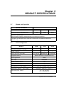
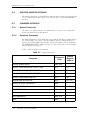
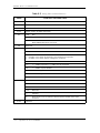
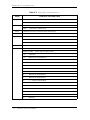
3.1 Models and Capacities
3.2 Drive Configuration
MODELS NUMBERS
RoHS Compliant
6K020L0 6K030L0 6K040L0
Formatted Capacity (GB LBA Mode) 20GB 30GB 40GB
GB means 1 billion bytes.
Total accessible capacity varies depending on operating environment.
* Complies with European Union Directive on Restriction of Hazardous Substances
(Section 3.13)
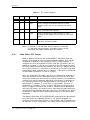
MODELS 20GB 30GB 40GB
Data Surfaces/Number of Heads 1 1 1
Number of Disks 111
Sectors per Drive (max LBA) 40,718,160 60,058,656 80,293,248
Integrated Interface Maxtor Ultra ATA/133 (ATA-5/ATA-6)
Recording Method PRML
Servo Type Embedded
Number of Servo Sectors 180
Data Zones per Surface 16
Data Sectors per Track (ID/OD) 450/720, 612/990, 720/1140
Areal Density (Gbits/in
2
max, ID/OD) 33.9/25.6, 46.6/36.1, 63.2/49.7
Flux Density (kfci, ID/OD) OD=352/496/583
ID = 465/639/743

Product Specifications
3-2 Quickview 40 20/30/40GB AT
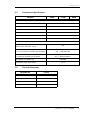
Recording Density (kbpi, ID/OD) ID = 446/613/713
OD = 338/476/560
Track Density (ktpi) 75.9/75.9/88.7
MODELS 20GB 30GB 40GB

Product Specifications
Quickview 40 20/30/40GB AT 3-3
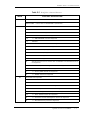
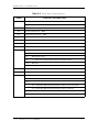
3.3 Performance Specifications
3.4 Physical Dimensions
MODELS 20GB 30GB 40GB
Seek Times (typical read, ms)
Track-to-Track 0.8
Average (normal seek)
≤ 10.0
Full Stroke (normal seek)
≤ 18.0
Average Latency (ms) 4.17
Controller Overhead (ms) <0.3
Rotation Speed (RPM ±0.1%) 7200
Data Transfer Speed (MByte/sec max)
To/From Interface
(Maxtor Ultra ATA/133, up to)
133
To/From Media (ID/OD up to nn.n, where
nn.n is the maximum transfer rate possible)
ID = 290/399/463
OD = 454/636/738
Sustained (ID/OD up to nn.n, where nn.n is
the maximum transfer rate possible)
ID = 23.9/32.5/38.2
OD = 38.2/52.6/60.5
Data Buffer Size (MB)/Type 2/SDRAM
Drive Ready Time (typical sec) <5.0
PARAMETER VALUE
Height (maximum in mm) 17.5
Width (typical mm) 101.6
Length (maximum in mm) 146.1
Weight (maximum in grams)
≤ 510

Product Specifications
3-4 Quickview 40 20/30/40GB AT
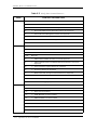
3.5 Power Requirements
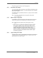
3.6 Power Mode Definitions
Spin-up
The drive is spinning up following initial application of power and has
not yet reached full speed.
Seek
A random access operation by the drive.
Read/Write
Data is being read from or written to the drive.
Idle
The drive is spinning, the actuator is parked and powered off and all
other circuitry is powered on.
The drive is capable of responding to read commands within 40 ms.
Standby
The motor is not spinning. The drive will leave this mode upon receipt
of a command that requires disk access. The time-out value for this
mode is programmable. The buffer is active to accept write data.
Sleep
This is the lowest power state – with the interface set to inactive. A
software or hardware reset is required to return the drive to the Standby
state.
3.7 EPA Energy Star Compliance
Maxtor Corporation supports the goals of the U.S. Environmental
Protection Agency’s Energy Star program to reduce the electrical power
consumption of computer equipment.
MODE 12V (MA) 5V (MA) POWER (W)
Spin-up (peak) 1554.20 756.04 22.43
Seek 440.42 562.13 8.10
Read/Write 489.99 442.42 8.09
Idle 380.57 396.41 7.27
Standby 34.35 65.83 0.75
Sleep 34.25 65.77 0.75
Page is loading ...
Page is loading ...
Page is loading ...
Page is loading ...
Page is loading ...
Page is loading ...
Page is loading ...
Page is loading ...
Page is loading ...
Page is loading ...
Page is loading ...
Page is loading ...
Page is loading ...
Page is loading ...
Page is loading ...
Page is loading ...
Page is loading ...
Page is loading ...
Page is loading ...
Page is loading ...
Page is loading ...
Page is loading ...
Page is loading ...
Page is loading ...
Page is loading ...
Page is loading ...
Page is loading ...
Page is loading ...
Page is loading ...
Page is loading ...
Page is loading ...
Page is loading ...
Page is loading ...
Page is loading ...
Page is loading ...
Page is loading ...
Page is loading ...
Page is loading ...
Page is loading ...
Page is loading ...
Page is loading ...
Page is loading ...
Page is loading ...
Page is loading ...
Page is loading ...
Page is loading ...
Page is loading ...
Page is loading ...
Page is loading ...
-
 1
1
-
 2
2
-
 3
3
-
 4
4
-
 5
5
-
 6
6
-
 7
7
-
 8
8
-
 9
9
-
 10
10
-
 11
11
-
 12
12
-
 13
13
-
 14
14
-
 15
15
-
 16
16
-
 17
17
-
 18
18
-
 19
19
-
 20
20
-
 21
21
-
 22
22
-
 23
23
-
 24
24
-
 25
25
-
 26
26
-
 27
27
-
 28
28
-
 29
29
-
 30
30
-
 31
31
-
 32
32
-
 33
33
-
 34
34
-
 35
35
-
 36
36
-
 37
37
-
 38
38
-
 39
39
-
 40
40
-
 41
41
-
 42
42
-
 43
43
-
 44
44
-
 45
45
-
 46
46
-
 47
47
-
 48
48
-
 49
49
-
 50
50
-
 51
51
-
 52
52
-
 53
53
-
 54
54
-
 55
55
-
 56
56
-
 57
57
-
 58
58
-
 59
59
-
 60
60
-
 61
61
-
 62
62
-
 63
63
-
 64
64
-
 65
65
-
 66
66
-
 67
67
-
 68
68
-
 69
69


Maxtor 1925 User manual
- Category
- Internal hard drives
- Type
- User manual
- This manual is also suitable for
Ask a question and I''ll find the answer in the document
Finding information in a document is now easier with AI
Related papers
-
Maxtor 300 User manual
-
Seagate STM900603OTABE1-RK Maxtor OneTouch III Mini Edition User manual
-
-
-
-
Seagate Maxtor Shared Storage Installation guide
-
-
Seagate 6N040T0-25PK User manual
-
Seagate 6Y120M0 DIAMOND MAX + 9 Datasheet
-
Other documents
-
-
LogiLink AD0005 Datasheet
-
-
-
Hitachi DK23FB-40 Quick Installation Manual
-
Samsung SV1204H Datasheet
-
Toshiba MK6017MAP User manual
-
-
Bull 20/40GB 4mm Internal Tape Drive Installation guide
-