Whirlpool 3369092 REV. A User manual
- Category
- Dishwashers
- Type
- User manual
This manual is also suitable for
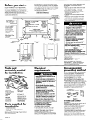
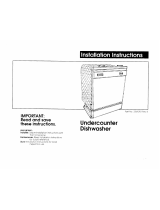
Whirlpool 3369092 REV. A is an undercounter dishwasher that offers convenient loading and efficient cleaning. It requires a 120-volt, 60 Hz, AC-only, 15- or 20-ampere, fused electrical supply and a hot water line that provides between 15 - 120 psi water pressure. The drain hose must have a high drain loop, 20” minimum ABOVE FLOOR, to prevent backflow or water siphoning out of the dishwasher during operation. It's important to note that the dishwasher is shipped to be installed in a cabinet opening with a 34” height.
Whirlpool 3369092 REV. A is an undercounter dishwasher that offers convenient loading and efficient cleaning. It requires a 120-volt, 60 Hz, AC-only, 15- or 20-ampere, fused electrical supply and a hot water line that provides between 15 - 120 psi water pressure. The drain hose must have a high drain loop, 20” minimum ABOVE FLOOR, to prevent backflow or water siphoning out of the dishwasher during operation. It's important to note that the dishwasher is shipped to be installed in a cabinet opening with a 34” height.


-
 1
1
-
 2
2
-
 3
3
-
 4
4
-
 5
5
-
 6
6
-
 7
7


Whirlpool 3369092 REV. A User manual
- Category
- Dishwashers
- Type
- User manual
- This manual is also suitable for
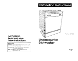
Whirlpool 3369092 REV. A is an undercounter dishwasher that offers convenient loading and efficient cleaning. It requires a 120-volt, 60 Hz, AC-only, 15- or 20-ampere, fused electrical supply and a hot water line that provides between 15 - 120 psi water pressure. The drain hose must have a high drain loop, 20” minimum ABOVE FLOOR, to prevent backflow or water siphoning out of the dishwasher during operation. It's important to note that the dishwasher is shipped to be installed in a cabinet opening with a 34” height.
Ask a question and I''ll find the answer in the document
Finding information in a document is now easier with AI
Related papers
-
Whirlpool Undercounter Dishwasher Installation Instructions Manual
-
-
Whirlpool RUD6000PB2 Installation guide
-
-
Whirlpool DU925SCGQ3 Installation guide
-
-
Whirlpool WDT970SAHV Installation guide
-
Whirlpool ADB1400AGS3 Owner's manual
-
-
Other documents
-
 Benton Harbor 3369093 Installation Instructions Manual
-
Maytag MDB4621AWB - Full Console Dishwasher Installation Instructions Manual
-
Kenmore Elite 66512779K311 Installation guide
-
Kenmore 66516641891 Installation guide
-
 Benton Harbor 3369093 Installation Instructions Manual
-
GE GSM2100GBB Installation guide
-
Dacor RDW24I Installation guide
-
Maytag 3369685 Installation Instructions Manual
-
IKEA IUD8500BX0 Installation guide
-
KitchenAid KDPE234GBS Installation guide

