Elektra Beckum BAS 316G WNB User manual
- Category
- Circular saws
- Type
- User manual
This manual is also suitable for

115 166 9103 / 4802 - 1.1
BAS 316G DNB /
BAS 316G WNB
Betriebsanleitung. . . . . . . . . . . . . . . . . . . . .3
Operating Instruction . . . . . . . . . . . . . . . . .15
Instructions d'utilisation . . . . . . . . . . . . . . .27
Manuale d’istruzioni. . . . . . . . . . . . . . . . . .39
Manual de uso . . . . . . . . . . . . . . . . . . . . . .51
A0151IVZ.fm

2
D DEUTSCH ENG ENGLISH
KONFORMITÄTSERKLÄRUNG DECLARATION OF CONFORMITY
Wir erklären in alleiniger Verantwortlichkeit, dass dieses Produkt mit
den folgenden Normen übereinstimmt* gemäß den Bestimmungen
der Richtlinien**
EG-Baumusterprüfung *** durchgeführt von ****
We herewith declare in our sole repsonsibility that this product
complies with the following standards*
in accordance with the regulations of the undermentioned Directives**
EC type examination *** conducted by ****
F FRANÇAIS NL NEDERLANDS
DECLARATION DE CONFORMITE CONFORMITEITSVERKLARING
Nous déclarons, sous notre seule responsabilité, que ce produit est en
conformité avec les normes ou documents normatifs suivants* en
vertu des dispositions des directives **
Contrôle européen du modèle type *** effectué par ****
Wij verklaren als enige verantwoordelijke, dat dit product in
overeenstemming is met de volgende normen*
conform de bepalingen van de richtlijnen** EG-typeonderzoek ***
uitgevoerd door ****
IT ITALIANO ES ESPA
Ñ
OL
DICHIARAZIONE DI CONFORMITÀ DECLARACION DE CONFORMIDAD
Noi dichiariamo sotto la nostra esclusiva responsabilità che il presente
prodotto è conforme alle seguenti norme* in conformità con le
disposizioni delle normative ** Omologazione CE *** eseguita da ****
Declaramos bajo nuestra exclusiva responsabilidad, que el presente
producto cumple con las siguientes normas* de acuerdo a lo
dispuesto en las directrices** Homologación de tipo CE *** llevada a
cabo por ****
PT PORTUGU
Ê
S SV SVENSKA
DECLARAÇÃO DE CONFORMIDADE
F
Ö
RS
Ä
KRAN OM
Ö
VERENSST
Ä
MMELSE
Declaramos sob nossa responsabilidade que este produto está de
acordo com as seguintes normas* de acordo com as directrizes dos
regulamentos ** controle de amostra de Construção da CE ***
efectuado por ****
Vi försäkrar på eget ansvar att denna produkt överensstämmer med
följande standarder* enligt bestämmelserna i direktiven**
EG-materialprovning *** genomfört av ****
FIN SUOMI NO NORGE
VAATIMUKSENMUKAISUUSVAKUUTUS SAMSVARSERKLÆRING
Vakuutamme, että tämä tuote vastaa seuraavia normeja* on
direktiivien määräysten mukainen**
EY-tyyppitarkastustesti *** testin suorittaja: ****
Vi erklærer under eget ansvar at dette produkt samsvarer med
følgende normer* henhold til bestemmelsene i direktiv**
EU-typegodkjennelse *** utstilt av ****
DA DANSK POL POLSKI
OVERENSSTEMMELSESATTEST OŚWIADCZENIE O ZGODNOŚCI
Hermed erklærer vi på eget ansvar, at dette produkt stemmer overens
ed følgende standarder* iht bestemmelserne i direktiverne** EF-
typekontrol *** gennemført af ****
Oświadczamy z pełną odpowiedzialnością, że niniejszy produkt
odpowiada wymogom następujących norm* według ustaleń
wytycznych **Kontrola wzorców UE *** przeprowadzone przez ****
EL ΕΛΛHNIKA HU MAGYAR
∆ΗΛΩΣΗ ΑΝΤΙΣΤΟΙΧΕΙΑΣ MEGEGYEZŐSÉGI NYILATKOZAT
∆ηλώνουµε µε ιδία ευθύνη ότι το προϊόν αυτό αντιστοιχεί στις
ακόλουθες προδιαγραφές*
σύµφωνα µε τις διατάξεις των οδηγιών**
Έλεγχος-ΕΟΚ δοµικού πρωτοτύπου*** πραγµατοποιούµενος από
το****
Kizárólagos felelősségünk tudatában ezennel igazoljuk, hogy ez a
termék kielégíti az alábbi szabványokban lefektetett követelményeket*
megfelel az alábbi irányelvek előírásainak**
által végzett vizsgálat szerint megegyezik az alábbi építési
mintapéldánnyal *** a ****
BAS 316 G
*EN 61029, E DIN VDE 0740 - 504, EN 55014-1, EN 55014-2, EN 61000-3-2, EN 61000-3-3, DIN EN 62079
** 98/37/EG, 89/336/EWG, 73/23/EWG, 93/68/EWG
*** BM 2010949
**** TÜV-Rheinland, Am Grauen Stein, D-51105 Köln
Ing. grad. Hans-Joachim Schaller
Leitung Entwicklung und Konstruktion
Metabowerke GmbH
Business Unit Elektra Beckum
Daimler Str. 1
D - 49716 Meppen
Meppen, 22.08.2002 1001095/ 02

15
ENGLISH
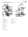
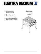
1. Parts identification (standard delivery)
2
5
6
7
8
91112
13
1
14
15
16
17
18
19
10
3
4
Front
1 Upper housing door
2 Setting knob for band saw
blade tension
3 Upper band saw wheel
4 Setting knob for blade guard
5 Blade guard
6 Band saw blade
7 Saw table
8 Fence guide extrusion,
graduated
9 Lower band saw wheel
10 Chip case
11 Rip fence
12 Lower housing door
13 On/Off switch with emergency
stop
Rear
14 Setting knob for blade tracking
adjustment
15 Motor
16 Machine base
17 Dust extraction port
18 Setting knob for drive belt
19 Table insert
XA0027E2.fm Operating Instruction ENGLISH

16
ENGLISH
1. Parts identification
(standard delivery)....................15
2. Please read first! .......................16
3. Safety .........................................16
3.1 Specified conditions of use .........16
3.2 General safety information..........16
3.3 Safety devices.............................17
4. Special product features ..........18
5. Transporting the saw................18
6. Machine details ........................18
7. Initial operation .........................19
7.1 Mounting .....................................19
7.2 Saw table installation ..................19
7.3 Saw table alignment....................19
7.4 Fence guide extrusion
installation ...................................20
7.5 Rip fence installation...................20
7.6 Dust collector connection............20
7.7 Band saw blade tensioning .........20
7.8 Installation of the
combination switch/plug..............20
7.9 Mains connection ........................20
8. Operation ...................................21
8.1 Sawing ........................................22
9. Care and Maintenance..............22
9.1 Band saw blade change..............22
9.2 Band saw blade alignment..........22
9.3 Upper blade guide alignment ......22
9.4 Lower blade guide alignment ......23
9.5 Band saw tyre replacement.........24
9.6 Table insert replacement.............24
9.7 Saw Cleaning..............................24
9.8 Saw storage ................................24
10. Tips and tricks...........................24
11. Available accessories..........24/63
12. Repairs.......................................25
13. Environmental protection.........25
14. Trouble shooting.......................25
15. Technical specifications...........25
15.1 Available band saw blades..........26
1
These instructions have been written in
a way which facilitates learning of how to
safely operate your saw. Here is a guide
on how you should read these instruc-
tions:
− Read these instructions before use.
Pay special attention to the safety
information.
− These instructions are intended for
persons having a basic technical
knowledge of the operation of
machines such as the one
described herein. If you have no
experience whatsoever, we strongly
recommend to seek the advise of an
experienced person.
− Keep all documents supplied with
this machine for future reference.
Retain proof of purchase in case of
warranty claims.
− If you lend or sell this machine be
sure to have all machine documents
supplied go with it.
− The equipment manufacturer is not
liable for any damage resulting from
neglect of these operating instruc-
tions.
Information in these instructions is
denoted as under:
Danger!
Risk of personal injury or
environmental damage.
Risk of electric shock!
Risk of personal injury
by electric shock.
Drawing-in/trapping haz-
ard!
Risk of personal injury
by body parts or clothing
being caught.
Caution!
Risk of material damage.
Note:
Additional information.
− Numbers in illustrations (1, 2, 3, ...)
− indicate component parts;
− are consecutively numbered;
− relate to the corresponding
number(s) in brackets (1), (2), (3)
... in the neighbouring text.
− Instructions to be carried out in a
certain sequence are numbered.
− Instructions which can be carried
out in any sequence are marked by
a bullet (•).
− Listings are marked by an En dash
(–).
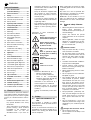
3.1 Specified conditions of
use
This bandsaw is suitable for cutting
wood, plastics, metals (no hard metal or
hardened metal).
Do not cut round stock transverse to its
longitudinal axis without suitable jigs or
fixtures. The rotating saw blade could
turn the workpiece.
When sawing thin stock layed on edge,
a suitable guide must be used for firm
support.
Any other use is not as specified. The
manufacturer is not liable for any dam-
age caused by unspecified use.
Modification of the machine or use of
parts not approved by the equipment
manufacturer can cause unforeseeable
damage!
3.2 General safety informa-
tion
• When using this tool observe the fol-
lowing safety instructions, to
exclude the risk of personal injury or
material damage.
• Please also observe the special
safety instructions in the respective
chapters.
• Where applicable, follow the legal
directives or regulations for the pre-
vention of accidents pertaining to
the use of band saws.
A
General hazards!
• Keep your work area tidy – a messy
work area invites accidents.
• Be alert. Know what you are doing.
Set out to work with reason. Do not
operate tool while under the influ-
ence of drugs, alcohol or medica-
tion.
• Consider environmental conditions:
keep work area well lighted.
• Prevent adverse body positions.
Ensure firm footing and keep your
balance at all times.
• When working long stock use suita-
ble supports.
• Do not operate tool near inflamma-
ble liquids or gases.
• The machine shall only be started
and operated by persons familiar
with bandsaws and who are at any
time aware of the dangers associ-
ated with the operation of such tool.
Persons under 18 years of age shall
use this tool only in the course of
their vocational training, under the
supervision of an instructor.
• Keep bystanders, particularly chil-
dren, out of the danger zone. Do not
permit other persons to touch the
tool or power cable while it is run-
ning.
• Do not overload tool – use it only
within the performance range it was
designed for (see “Technical specifi-
cations”).
B
Danger! Risk of electric shock!
• Do not expose tool to rain.
Do not operate tool in damp or wet
environment.
Table of Contents
2. Please read first!
3. Safety

17
ENGLISH
Prevent body contact with earthed
objects such as radiators, pipes,
cooking stoves, refrigerators when
operating this tool.
• Do not use the power cable for any
purpose it is not intended for.
A
Risk of injury by moving parts!
• Do not operate the tool without
installed guards.
• Always keep sufficient distance to
the band saw blade. Use suitable
feeding aids, if necessary. Keep suf-
ficient distance to driven compo-
nents when operating this tool.
• Wait for the band saw blade to come
to a complete stop before removing
cutoffs, scrap, etc. from the work
area.
• Cut only stock of dimensions that
allow for safe and secure holding
while cutting.
• Do not attempt to stop the band saw
blade by pushing the workpiece
against its side.
• Ensure tool is disconnected from
power supply before servicing.
• Ensure that when switching on (e.g.
after servicing) no tools or loose
parts are left on or in the tool.
• Unplug if the tool is not used.
A
Cutting hazard, even with the
cutting tool at standstill!
• Wear gloves when changing cutting
tools.
• Store band saw blades in such man-
ner that nobody will get hurt.
A
Risk of kickback (workpiece is
caught by the band saw blade and
thrown against the operator)!
• Do not jam workpieces.
• Cut thin or thin-walled workpieces
only with fine-toothed band saw
blades. Always use sharp band saw
blades.
• If in doubt, check workpiece for
inclusion of foreign matter (e.g. nails
or screws).
• Cut only stock of dimensions that
allow for safe and secure holding
while cutting.
• Never cut several workpieces at the
same time – and also no bundles
containing several individual pieces.
Risk of personal injury if individual
pieces are caught by the band saw
blade uncontrolled.
• When cutting round stock, use a
suitable jig to prevent the workpiece
from turning.
c
Drawing-in/trapping hazard!
• Ensure that no parts of the body or
clothing can be caught and drawn in
by rotating components (no neck-
ties, no gloves, no loose-fitting
clothes; contain long hair with hair-
net).
• Never saw workpieces containing
the following materials:
− ropes
− strings
− cords
− cables
− wires.
A
Hazard generated by insuffi-
cient personal protection gear!
• Wear hearing protection.
• Wear safety glasses.
• Wear dust mask.
• Wear suitable work clothes.
• When working outdoors wearing of
non-slip shoes is recommended.
A
Risk of injury by inhaled wood
dust!
• Dust of certain timber species (e.g.
oak, beech, ash) can cause cancer
when inhaled: work only with a suit-
able dust collector connected to the
saw. The dust collector must comply
with the data stated in the technical
specifications.
• See to it that only as little as possi-
ble wood dust will get into the envi-
ronment:
− Remove wood dust deposit in the
work area (do not blow away!);
− fix any leakages on the dust col-
lector;
− ensure good ventilation.
A
Hazard generated by modifica-
tion of the machine, or use of parts
not tested and approved by the equip-
ment manufacturer!
• Assemble tool in strict accordance
with these instructions.
• Use only parts approved by the
equipment manufacturer. This
applies especially for:
− band saw blades (see “Technical
specifications” for stock nos.);
− safety devices (see “Technical
specifications” for stock nos.).
• Do not change any parts.
A
Hazard generated by tool
defects!
• Keep tool and accessories in good
repair. Observe the maintenance
instructions.
• Before any use check tool for possi-
ble damage: before operating the
tool all safety devices, protective
guards or slightly damaged parts
need to be checked for proper func-
tion as specified. Check to see that
all moving parts work properly and
do not jam. All parts must be cor-
rectly installed and meet all condi-
tions necessary for the proper oper-
ation of the tool.
• Damaged protection devices or
parts must be repaired or replaced
by a qualified specialist. Have dam-
aged switches replaced by a service
centre. Do not operate tool if the
switch can not be turned ON or
OFF.
• Keep handles free of oil and grease.
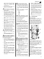
3.3 Safety devices
Upper blade guard
The upper blade guard (20) protects
against unintentional contact with the
saw blade and from chips flying about.
In order for the upper blade guard to pro-
vide adequate protection against contact
with the band saw blade, it must always
be set as close as possible against the
workpiece (max. distance 3 mm).
Lower blade guard
The lower blade guard (21) protects
against inadvertent contact with the
band saw blade. When closing the lower
housing door, the lower blade guard
swings over the band saw blade.
The lower blade guard must always be
installed during operation.
Housing doors
The housing doors (22) protect against
contact with the rotating parts inside the
machine.
To lock or unlock the housing doors, turn
the locks a quarter turn with a suitable
slotted bit screwdriver.
The lower housing door is equipped with
a door catch (23). The door catch pre-
vents the closing of the lower housing
door without the chip case (24) being in
place.
20
21
22

18
ENGLISH
Both housing doors must be closed
while the machine is in use.
Electronic motor brake
The wear-free electronic motor brake
(inside the saw, not illustrated) causes
the band saw blade to stop within 10
seconds after the saw is turned OFF.
If the time to standstill exceeds 10 sec-
onds the ON/OFF switch is faulty and
needs to be replaced by a qualified elec-
trician without delay.
• Cast grey iron table.
• Upper blade guide with 3 bearings.
• Chip case for convenient disposal of
chips.
• Scale for cutting height.
• Up-to-date technology, designed for
lasting durability and accuracy.
• GS-approved for low dust emission
• Adjust upper blade guide to its low-
est position.
• Remove projecting accessories.
• When shipping, use original packing
if possible.
3
Note:
In this chapter the essential oper-
ating elements of the machine are intro-
duced.
The proper use of the saw is detailed in
chapter “Operation”. Read this chapter
before using the saw for the first time.
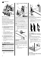
On/Off switch with emergency stop
• To start = press green switch button
(25).
• To stop = press red switch button
(26) or cover (27) of the ON/OFF
switch.
In the event of a voltage failure an und-
ervoltage relay will trip. This prevents the
machine from starting up when the
power is restored. To restart, the green
switch button must be pressed.
The cover of the ON/OFF switch (27)
can be safeguarded by a padlock.
Setting knob for band saw blade ten-
sion
With the setting knob (28) the band saw
blade tension is corrected, if necessary:
− Turning the setting knob clockwise
increases the blade tension.
− Turning the setting knob counter-
clockwise reduces the blade ten-
sion.
Setting knob for blade tracking
adjustment
With the setting knob (29) the tilt of the
upper band saw wheel can be adjusted,
if necessary. This tracking adjustment is
required to have the blade run dead cen-
tre on the rubber tyres of the band saw
wheels:
− turning clockwise = blade moves to
the rear
− Turning counter-clockwise = blade
moves to the front.
Speed adjustment
By shifting the drive belt the band saw
can be operated at two speeds (see
“Technical specifications”):
− 370 m/min for hard wood, plastics
and non-ferrous metals (with special
band saw blade);
− 800 m/min for all kinds of wood.
A
Caution!
The drive belt must not run in a
diagonal position; this will damage
the belt
Setting knob for drive belt tension
With the setting knob (30) the drive belt
tension is corrected, if necessary:
− turning the setting knob clockwise
lessens the blade tension;
− turning the setting knob counter-
clockwise increases the blade ten-
sion.
Saw table tilt
After loosening the locking screw (31)
the saw table (32) tilts steplessly through
45° against the blade.
4. Special product features
5. Transporting the saw
6. Machine details
23
24
25
26
27
28
29
800 m/min370 m/min
30

19
ENGLISH
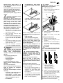
Rip fence
The rip fence (33) is clamped to the
front. The rip fence can be used on both
sides of the blade.
A
Danger!
Start the saw only after the fol-
lowing preparations have been com-
pleted:
− the saw is fastened;
− the saw table is installed and
aligned;
− the V-belt tension checked;
− the combination switch/plug is
installed;
− the safety devices have been
checked.
Connect the saw to the mains supply
only after all of the above prepara-
tions are completed! Otherwise there
is a risk of an unintentional starting of
the saw, which may cause severe per-
sonal injury.
7.1 Mounting
For a firm stand the saw must be
mounted on a stable supporting surface:
1. Drill four holes in the supporting sur-
face.
2. Put fixing bolts through the base
plate and secure with nuts.
Optimal working height and stability is
provided by the workstand (optional
accessory), which is already prepared
for mounting the saw.
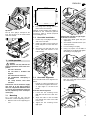
7.2 Saw table installation
1. Fit limit stop screw (34) to the under-
side of the saw table.
2. Guide saw table over the band saw
blade and place it on the table trun-
nion.
3. Attach the saw table with four each
screws (35) and washers to the
table trunnion.
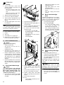
7.3 Saw table alignment
The saw table needs to be aligned in two
planes
− laterally, in order for the blade to run
dead centre through the table insert;
− at right angles to the band saw
blade.
Saw table lateral alignment
1. Loosen the four fastening screws
(36) that hold the lower table trun-
nion.
2. Align saw table so that the blade
runs through the centre of the table
insert's slot.
3. Tighten the four fastening screws
(36) again.
Aligning the saw table at right angles
to the band saw blade
1. Raise upper blade guide fully (see
“Operation”).
2. Check band saw blade tension (see
“Initial operation”).
3. Loosen locking screw (37).
4. Using a try square, set the table at
right angles to the blade and tighten
the locking screw (37) again.
5. Loosen locking nut (38) and adjust
limit stop screw (39) until it touches
the saw housing.
6. Tighten locking nut.
7. Initial operation
31
32
33
428 mm
312 mm
458 mm
342 mm
34
35
36
37
39
38

20
ENGLISH
7.4 Fence guide extrusion
installation
• Fasten the fence guide extrusion
(40) with four each thumb screws
and washers to the saw table.
7.5 Rip fence installation
The rip fence can be used on both sides
of the blade.
1. Fasten the fence extrusion (41),
using
− two each pan-head screws,
− two each washers and
− two each knurled nuts
to the fence guide.
2. Attach the thus assembled rip fence
with one each
− pan-head screw,
− washer and
− wing nut
to the fence guide extrusion (42).
Rip fence alignment
1. Loosen the two small knurled nuts
(43) approx. one turn.
2. Turn the large knurled thumb screw
(44) as required to set the rip fence
square against the saw table.
3. Tighten both small knurled nuts (43)
again.
Scale installation
• Affix the self-adhesive scale (45) on
the fence guide extrusion, so that
the zero position is opposite of the
band saw blade. For an exact align-
ment set the rip fence against the
saw blade.
7.6 Dust collector connec-
tion
A
Danger!
Some types of saw dust (e.g. of
oak, beech and ash wood) can cause
cancer when inhaled: always use a
dust collector when working indoors
(required air speed at the saw's suc-
tion connector ≥ 20 m/s).
A
Caution!
Operation without a dust col-
lector is only possible:
− outdoors;
− for short-term operation
(up to 30 minutes maximum);
− with dust respirator.
− If no dust collector is used chips
will accumulate, which need to be
removed periodically.
Connect dust collector or industrial vac-
uum with a suitable adaptor to the dust
extraction port.
7.7 Band saw blade tension-
ing
A
Danger!
Too much tension can cause
the band saw blade to break.Too little
tension can cause the driven band
saw wheel to slip and the band saw
blade to stop.
1. Raise upper blade guide fully (see
“Operation”).
2. Check tension by pushing with a fin-
ger, halfway between table and
upper blade guide, against the side
of the blade. The blade should flex
not more than 1-2 mm.
3. Correct tension if necessary:
− turning the setting knob (46)
counter-clockwise increases the
blade tension.
− turning the setting knob (46)
counter-clockwise reduces the
blade tension.
7.8 Installation of the combi-
nation switch/plug
1. Fit cable bushing (47) in the hole
provided in the band saw frame.
2. Fasten the combination switch/plug
with two screws to the band saw
frame.
7.9 Mains connection
B
Danger! High voltage
Operate the band saw in dry
surroundings only.
Operate the saw only on a power
source matching the following
requirements (see also “Technical
specifications”):
− fuse protection by a residual cur-
rent operated device (RCD) of
30 mA sensitivity;
− outlets properly installed, earthed
and tested;
− Three-phase outlets with neutral
wire installed;
3
Note:
Check with your local Electricity
Board or your electrician if in doubt
whether your house service connection
meets the requirements.
40
41
42
2
2
3
3
4
4
5
5
43
44
45
46
47

21
ENGLISH
Position power supply cable so it
does not interfere with the work and
is not damaged.
Protect power supply cable from heat,
aggressive liquids and sharp edges.
Use only rubber jacketed cable of suf-
ficient lead cross section.
Do not pull on power supply cable to
unplug.
A
Changing the direction of rota
tion (3-phase motor only):
Depending on phase sequence the
band saw blade may turn in the wrong
direction. This can cause the work-
piece being tossed away when
attempting to cut. Therefore, always
check direction of rotation after every
connection to the power supply.
If the direction of rotation is incorrect,
the electrical connection must be
changed by a qualified electrician!
1. When the saw is assembled and all
safety devices are installed, connect
it to the power supply.
2. Start saw briefly and turn OFF
immediately again.
3. Check the band saw blade's direc-
tion of rotation: in the cutting area
it must run from the top down-
wards.
4. If the band saw blade turns in the
wrong correction, unplug the power
supply cable at the saw.
5. Have the electrical connection
changed by a qualified electrician!
A
Danger!
To reduce the risk of personal
injury as much as possible, the fol-
lowing safety recommendations
should be observed when operating
the saw.
Use personal protection gear:
− dust respirator;
− hearing protection;
− safety goggles.
Cut only one workpiece at a time.
Always hold the workpiece down on
the table.
Do not jam the workpiece.
Do not attempt to stop the band saw
blade by pushing the workpiece
against its side.
If the type of work requires, use the
following:
− push stick – if distance rip fence
– band saw blade ≤ 120 mm;
− work support – for long stock,
which would otherwise fall off the
table on completion of the cut;
− dust collector;
− an appropriate jig when cutting
round stock, to keep it from turn-
ing;
− a suitable guide for firm support
when cutting thin stock layed on
edge.
Before starting work, check to see
that the following are in proper work-
ing order:
− band saw blade;
− upper and lower blade guard.
Replace damaged parts immediately.
Assume correct work position (the
band saw blade's teeth must point
towards the operator).
Never cut several workpieces at the
same time – and also no bundles con-
taining several individual pieces. Risk
of personal injury if individual pieces
are caught by the saw blade uncon-
trolled.
c
Drawing-in/trapping hazard!
Do not wear loose clothing,
jewellery, or gloves, which may get
caught and wound up by revolving
machine parts.
Contain long hair with a hairnet.
Never cut stock to which ropes,
cords, strings, cables and wires are
attached or which contain such mate-
rials.
Upper blade guide adjustment
The height of the upper blade guide (48)
needs to be adjusted:
− prior to every cutting operation, to
accommodate the height of the
workpiece (the upper blade guide
should be set approx. 3 mm above
the workpiece);
− after adjustments of band saw blade
or saw table (e.g. band saw blade
change, tensioning of the band saw
blade, saw table alignment).
A
Danger!
Before adjusting the upper
blade guide and saw table tilt:
− switch machine OFF.
− Wait until the band saw blade has
come to a complete stop.
1. Loosen locking screw (49).
2. Slide the upper blade guide (48) into
desired position.
3. Tighten the locking screw (49)
again.
Cutting speed adjustment
1. Open the lower housing door.
2. Slacken V-belt by turning the crank
clockwise.
3. Shift the V-belt to the desired pulley
on the drive wheel (lower band saw
wheel) and to the corresponding
motor pulley.
A
Caution!
The V-belt must run either on
both front or both rear pulleys. Never
have the V-belt run diagonally!
− V-belt on front pulley
= low speed, high torque.
− V-belt on rear pulleys
= high speed, low torque.
4. Tighten the V-belt again by turning
the crank counter-clockwise (half-
way between the pulleys the V-belt
should flex approx. 10 mm).
5. Close the lower housing door.
Information on how to set the cutting
speed can also be found on the label on
the inside of the lower housing door.
8. Operation
3 mm
48
49
800 m/min370 m/min

22
ENGLISH
8.1 Sawing
1. Choose and install a table insert
extrusion suitable for the type of cut
to be performed:
− table insert extrusion with a nar-
row slot for standard cross cuts
only;
− table insert extrusion with bevel-
led slot for bevel cuts also.
2. Adjust the band saw blade speed.
3. If necessary, adjust the table tilt.
4. Select rip fence and table tilt for the
type of cutting operation to be car-
ried out.
5. Set upper blade guide 3 mm above
the workpiece.
3
Note:
Always make a trial cut in a piece
of scrap to verify settings; correct if nec-
essary before cutting the workpiece.
6. Place workpiece on the saw table.
7. Plug in.
8. Start saw.
9. Cut workpiece in a single pass.
10. Switch off if no further cutting is to
be done immediately afterwards.
A
Danger!
Prior to all servicing:
− switch machine OFF.
− wait until the saw has come to a
complete stop.
− unplug power cable.
• Check that all safety devices are
operational again after each service.
• Replace defective parts, especially
of safety devices, only with genuine
replacement parts. Parts not tested
and approved by the equipment
manufacturer can cause unforeseen
damage.
• Repair and maintenance work other
than described in this section should
only be carried out by qualified spe-
cialists.
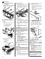
9.1 Band saw blade change
A
Danger!
Risk of injury, even with the
band saw blade at standstill. Wear
gloves when changing blades. Use
only suitable band saw blades (see
“Technical specifications”).
1. Loosen the four thumb screws (50)
and remove the fence guide extru-
sion (51).
2. Open both housing doors.
3. Adjust upper blade guide (52) to its
lowest position.
4. Loosen setting knob (53) until the
band saw blade has slackened.
5. To remove the band saw blade,
guide it through
− the slot in the saw table (54),
− the blade guard on the upper
blade guide (55),
− the blade cover on the saw hous-
ing (56) and
− the blade guides.
6. Fit fresh band saw blade. Observe
correct position: the teeth point
towards the front (door) side of the
saw.
7. Center band saw blade on the rub-
ber tyres of the band saw wheels.
8. Tighten setting knob until blade
does no longer slip off the band saw
wheels.
9. Close both housing doors.
10. Then:
− tension band saw blade (see “Ini-
tial operation”).
− align band saw blade (see “Care
and maintenance”);
− align blade guides (see “Care
and maintenance”);
− let saw test run for at least one
minute;
− stop saw, unplug and recheck
settings.
9.2 Band saw blade align-
ment
If the band saw blade does not run in the
centre of the rubber tyres, the tracking
needs to be corrected by adjusting the
tilt of the upper band saw wheel:
1. Loosen locking nut (57).
2. Turn setting knob (58):
− Turn setting knob (58) clockwise
if the band saw blade runs
towards the front of the saw.
− Turn setting knob (58) counter-
clockwise if the band saw blade
runs towards the rear of the saw.
3. Tighten locking nut (57).
9.3 Upper blade guide align-
ment
The upper blade guide consists of:
− a large thrust bearing (supports the
band saw blade from the rear),
− two smaller guide bearings (provid-
ing lateral support).
All bearings need to be readjusted after
every band saw blade change and/or
tracking.
3
Note:
Periodically check the guide
bearings for wear, if necessary replace
both guide bearings at the same time.
1. Turn the ratchet lock lever (59) to
loosen the thrust bearing (60), so it
will easily move in the direction of
arrows.
9. Care and Maintenance
50
51
52
53
54
55
56
57 58

23
ENGLISH
2. Loosen screws (61).
3. Adjust position of guide bearing sup-
port (62) so that the guide bearings
(63) are positioned approx. 1 mm
behind the tooth gullet.
4. Tighten screws (61) again.
5. Loosen screws (64).
6. Press guide bearings (65) together
(against the band saw blade).
7. Turn the band saw wheel by hand in
a clockwise direction several times
to bring the guide bearings in correct
position – both guide bearings
should just touch the band saw
blade.
8. Tighten screws (64) again.
9. Adjust thrust bearing position (67)
so it just touches the band saw
blade.
10. Tighten the ratchet lock lever (66)
again.
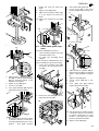
9.4 Lower blade guide align-
ment
The lower blade guide consists of:
− a thrust bearing (supports the band
saw blade from the rear),
− two guide pins (providing lateral
support).
These need to be readjusted after every
band saw blade change and/or tracking.
1. Loosen the four thumb screws (68)
and remove the fence guide extru-
sion (69).
2. Remove the saw table (70) from the
upper table trunnion (71).
3. Raise upper blade guide fully.
4. Loosen screw (72) so the thrust
bearing will slide back and forth eas-
ily.
5. Loosen screw (73).
6. Adjust position of supports (74) so
that the pilot pins (75) are positioned
approx. 1 mm behind the tooth gul-
let.
7. Tighten screw (73) again.
8. Loosen screws (76) with a hex.
wrench.
9. Press guide pins (77) together
(against the band saw blade).
10. Turn the band saw wheel by hand in
a clockwise direction several times
to bring the guide pins in correct
position – both guide pins should
just touch the band saw blade.
11. Tighten screws (76) again.
59
60
1mm
61
62
63
64
65
66
67
68
69
70
71
72
1mm
73
74
75
76
77

24
ENGLISH
12. Adjust thrust bearing position (78)
so it just touches the band saw
blade.
13. Tighten screw (79) again.
14. Reinstall the saw table on the upper
table trunnion.
15. Reinstall the fence guide extrusion
for the rip fence.
9.5 Band saw tyre replace-
ment
Periodically check band saw tyres for
wear. Replace only in pairs:
1. Remove band saw blade (see “Care
and maintenance”);
2. Lift band saw tyre with a small
screwdriver, then pull off the band
saw wheel.
3. Mount new band saw tyres and rein-
stall the band saw blade.
9.6 Table insert replacement
The table insert needs replacement
when its slot has become enlarged or
damaged.
1. Remove table insert (80) from saw
table (push up from underneath).
2. Fit new table insert.
9.7 Saw Cleaning
1. Open the lower housing door.
2. Remove the chip case (81) and
empty it.
3. Remove chips and saw dust with
brush or vacuum from:
− inside of the lower band saw
housing;
− blade guides;
− operating elements
4. Swing door catch lever (82) up and
put the chip case back in.
9.8 Saw storage
A
Danger!
Store saw so that
− it can not be started by unauthor-
ized persons and
− nobody can get hurt.
3
Note:
The ON/OFF switch can be safe-
guarded by a padlock.
A
Caution!
Do not store saw unprotected
outdoors or in damp environment.
• Keep surfaces of the saw table
clean – in particular, remove resin
residue with a suitable cleaning and
maintenance spray (optional acces-
sory).
• Afterwards, apply a light coat of slid-
ing compound (e.g. Waxilit).
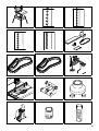
For special tasks the following accesso-
ries are available at your specialized
dealer – see back cover for illustrations:
A Workstand
for an optimal working height. Pow-
der-coated sheet-metal construc-
tion.
B Band saw blade
induction hardened teeth,
2240 x 12 x 0.5 A6,
for general cutting of wood.
C Band saw blade
induction hardened teeth,
2240 x 6 x 0.5 A6,
for contour cutting of wood.
D Band saw blade
induction hardened teeth,
2240 x 15 x 0.5 A6,
for standard cross cutting of wood.
E Band saw blade
induction hardened teeth,
2240 x 15 x 0.5 A2,
for non-ferrous metals.
F Belt sanding attachment
for finishing cut edges.
G Sanding belt
80 grit, 2240 x 20 (pack of 3 )
H Sanding belt
120 grit, 2240 x 20 (pack of 3 )
I Circle cutting attachment
for sawing circles of 120 to 260 mm
diameter. Optimum cutting results
when used with the contour cutting
blade.
J Mitre fence
for exact mitre cuts.
K Precision roller guide
provides optimum band saw blade
guiding and extended service life.
No tools required to adjust.
L Dust collection adapter for Ø 100
mm port.
M Dust collector
helps to protect your health and to
keep the shop clean.
N WAXILIT sliding compound
improves workpiece sliding on the
saw table.
O Care and maintenance spray
to remove resin residue and pre-
serve metal surfaces.
79
78
80
81
82
10. Tips and tricks
11. Available accessories

25
ENGLISH
A
Danger!
Repairs to power tools must be
carried out by qualified electricians
only!
Power tools in need of repair can be sent
to the service centre of your country.
Refer to the spare parts list for the
address.
Please attach a description of the fault to
the power tool.
The machine's packing can be 100%
recycled.
Worn out power tools and accessories
contain considerable amounts of valua-
ble raw and rubber materials, which can
be recycled.
These instructions are printed on paper
produced with elemental chlorine free
bleaching process.
A
Danger!
Before carrying out any fault
service or maintenance work always:
− switch machine OFF.
− unplug power cable.
− wait until the band saw blade has
come to a complete stop.
Check to see that all safety devices
are operational after each fault serv-
ice.
Motor does not run
Undervoltage relay tripped by power fail-
ure:
− switch on again.
No mains voltage:
− check cables, plug, outlet and mains
fuse.
Motor overheated, e.g. by a blunt band
saw blade or chip build-up in the hous-
ing:
− remove cause for overheating, let
cool down for a few minutes, then
start again.
Motor and band saw blade turn in the
wrong direction
Incorrect phase sequence (only possible
on 400 V-models):
− turn phase changer inside the com-
bination switch/plug (see “Initial
operation”).
Band saw blade coasting (≥ 10 s)
Electronic motor brake faulty:
− have ON/OFF switch replaced by a
qualified electrician.
Band saw blade wanders off the line
of cut or runs off the band saw
wheels
Band saw blade is not running dead cen-
tre on the band saw wheels:
− correct tracking (see “Care and
maintenance”).
Band saw blade breaks
Incorrect tension:
− correct band saw blade tension (see
“Initial operation”).
Load too high:
− reduce pressure against band saw
blade (reduced feed rate).
Incorrect band saw blade:
− replace band saw blade (see “Care
and maintenance”):
thin stock =
narrow band saw blade,
thick stock =
wide band saw blade.
Band saw blade warped
Load too high:
− avoid lateral pressure on the band
saw blade.
Saw vibrates
Insufficient mounting:
− Fasten saw properly to a suitable
surface (see “Initial operation”).
Saw table loose:
− align and fasten saw table.
Motor mount loose:
− check fastening screws, tighten if
necessary.
Dust extraction port blocked
No dust collector connected or suction
capacity insufficient:
− connect a dust collector or increase
suction capacity (air speed ≥20 m/
sec at dust extraction port).
12. Repairs
13. Environmental protection
14. Trouble shooting

26
ENGLISH
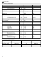
15.1 Available band saw blades
15. Technical specifications
Model BAS 316G DNB BAS 316G WNB
Voltage V 400 (3~ 50 Hz) 230 (1~ 50 Hz)
Capacity power input P1
effective shaft output P2
kW
kW
0.74
0.55
0.74
0.55
Nominal current A 1.5 3.5
Fuse protection A 10 (time-lag or K-Auto-
mat)
10 (time-lag or K-Auto-
mat)
Protection class IP 44 IP 44
Rated no-load speed min
-1
1400 ±10% 1400 ±10%
Cutting speed
High speed transmission ratio
Low speed transmission ratio
m/min
m/min
800 ±10%
370 ±10%
800 ±10%
370 ±10%
Band saw blade length mm 2240 2240
Max. throat capacity mm 300 300
Max. capacity under guide mm 160 160
Max. band saw blade width mm 15 15
Max. band saw blade thickness mm 0.5 0.5
Dimensions overall length
overall width
overall height
length saw table
width saw table
mm
mm
mm
mm
mm
590
610
1265
400
548
590
610
1265
400
548
Weight w/o accessories kg 60 60
Noise emission values, idle running,
Dust collection on
A-sound pressure level L
pA
A-sound power level L
WA
dB (A)
dB (A)
84.1
73.3
84.1
73.3
Noise emission values under load.
Dust collection on
A-sound pressure level L
pA
A-sound power level L
WA
dB (A)
dB (A)
85.5
79.4
85.5
79.4
Application Dimensions mm Tooth spacing Stock number
Wood general cutting 2240 x 12 x 0.5 A6 090 900 0467
Wood contour cutting 2240 x 6 x 0.5 A4 090 900 0475
Wood standard cross cutting 2240 x 15 x 0.5 A6 090 900 0483
Non-ferrous metals 2240 x 15 x 0.5 A2 090 900 0491

63
A 090 900 4276 B 090 902 9244 C 090 902 9252
D 090 902 9260 E 090 902 9279 F 090 901 8811
G 090 903 0528 H 090 903 0536 I 090 901 8366
J 091 000 8048 K 090 901 0900 L 091 003 1260
M 013 001 1004 N 431 306 2258 O 091 101 8691
45°
3
0°
0°
22,5°
30°
45°
15°
15°
22,5°
U3a0151.fm

ZINDEL - Technische Dokumentation und Multimedia, www.zindel.de
U4BA_EB3.fm
www.elektra-beckum.de
-
 1
1
-
 2
2
-
 3
3
-
 4
4
-
 5
5
-
 6
6
-
 7
7
-
 8
8
-
 9
9
-
 10
10
-
 11
11
-
 12
12
-
 13
13
-
 14
14
-
 15
15
-
 16
16


Elektra Beckum BAS 316G WNB User manual
- Category
- Circular saws
- Type
- User manual
- This manual is also suitable for
Ask a question and I''ll find the answer in the document
Finding information in a document is now easier with AI
Related papers
-
 Elektra Beckum TKHS 315 P User manual
-
Metabo PK 255/3,40 DNB User manual
-
 Elektra Beckum TKHS 315 (AUS) User manual
-
-
 Elektra Beckum UK 220 User manual
-
 Elektra Beckum TopLine PK 255 User manual
-
 Elektra Beckum SR 340 User manual
-
 Elektra Beckum Air Compressor Mega 350 D User manual
-
-


Other documents
-
Metabo BAS 505 Precision DNB Operating instructions
-
Palmgren Norse 9683124 User manual
-
Metabo BAS 317 Precision DNB Owner's manual
-
Global Machinery Company LS8B User manual
-
Wen 3914 User guide
-
-
-
-
Makita LB1200F User manual
-