Page is loading ...

115 119 4997 / 4300 - 6.0
UK 220
Betriebsanleitung. . . . . . . . . . . . . . . . . . . . .3
Operating Instruction . . . . . . . . . . . . . . . . .12
Instructions d’utilisation . . . . . . . . . . . . . . .21
Manuale d’istruzioni. . . . . . . . . . . . . . . . . .31
Manual de uso. . . . . . . . . . . . . . . . . . . . . .41
A0002IVZ.fm

2
U20002.fm
D DEUTSCH ENG ENGLISH
KONFORMITÄTSERKLÄRUNG DECLARATION OF CONFORMITY
Wir erklären in alleiniger Verantwortlichkeit, daß dieses Produkt mit
den folgenden Normen übereinstimmt* gemäß den Bestimmungen
der Richtlinien**
EG-Baumusterprüfung *** durchgeführt von ****
We herewith declare in our sole repsonsibility that this product
complies with the following standards*
in accordance with the regulations of the undermentioned Directives**
EC type examination *** conducted by ****
F
FRANÇAIS
NL
NEDERLANDS
DECLARATION DE CONFORMITE CONFORMITEITSVERKLARING
Nous déclarons, sous notre seule responsabilité, que ce produit est en
conformité avec les normes ou documents normatifs suivants* en
vertu des dispositions des directives **
Contrôle européen du modèle type *** effectué par ****
Wij verklaren als enige verantwoordelijke, dat dit product in
overeenstemming is met de volgende normen*
conform de bepalingen van de richtlijnen** EG-typeonderzoek ***
uitgevoerd door ****
IT
ITALIANO
ES
ESPAÑOL
DICHIARAZIONE DI CONFORMITÀ DECLARACION DE CONFORMIDAD
Noi dichiariamo sotto la nostra esclusiva responsabilità che il presente
prodotto è conforme alle seguenti norme* in conformità con le
disposizioni delle normative ** Omologazione CE *** eseguita da ****
Declaramos bajo nuestra exclusiva responsabilidad, que el presente
producto cumple con las siguientes normas* de acuerdo a lo
dispuesto en las directrices** Homologación de tipo CE *** llevada a
cabo por ****
PT
PORTUGUÊS
SV
SVENSKA
DECLARAÇÃO DE CONFORMIDADE
FÖRSÄKRAN OM ÖVERENSSTÄMMELSE
Declaramos sob nossa responsabilidade que este produto está de
acordo com as seguintes normas* de acordo com as directrizes dos
regulamentos ** controle de amostra de Construção da CE ***
efectuado por ****
Vi försäkrar på eget ansvar att denna produkt överensstämmer med
följande standarder* enligt bestämmelserna i direktiven**
EG-materialprovning *** genomfört av ****
FIN
SUOMI
NO
NORGE
VAATIMUKSENMUKAISUUSVAKUUTUS SAMSVARSERKLÆRING
Vakuutamme, että tämä tuote vastaa seuraavia normeja* on
direktiivien määräysten mukainen**
EY-tyyppitarkastustesti *** testin suorittaja: ****
Vi erklærer under eget ansvar at dette produkt samsvarer med
følgende normer* henhold til bestemmelsene i direktiv**
EU-typegodkjennelse *** utstilt av ****
DA
DANSK
POL
POLSKI
OVERENSSTEMMELSESATTEST
Hermed erklærer vi på eget ansvar, at dette produkt stemmer overens
ed følgende standarder* iht bestemmelserne i direktiverne** EF-
typekontrol *** gennemført af ****
wytycznych **Kontrola wzorców UE *** przeprowadzone przez ****
EL
HU
MAGYAR
termék kielégíti az alábbi szabványokban lefektetett követelményeket*
által végzett vizsgálat szerint megegyezik az alábbi építési
mintapéldánnyal *** a ****
UK 220
* EN 61029-1, DIN EN 294
** 98/37/EG, 73/23 EWG, 89/336/EWG
*** BG 9511244-01
**** TÜV Rheinland, Am Grauen Stein
D-51105 Köln
Jürgen Kusserow
Vorstand
ELEKTRA BECKUM AG – Daimlerstraße 1 – 49716 Meppen
1000923/00
2

12
ENGLISH
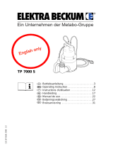
1. Getting to Know Your Saw
12
3
4
5
678910
1 Riving knife
2 Blade guard
3 Universal fence
4 Push stick / feeding aid
5 Handwheel for blade tilt setting
6 Handwheel for depth of cut set-
ting and pull action
7 Pull-action lock lever
8 Ratchet lock lever to lock saw
blade tilt
9 Lever, blade tilt limiter
10 ON/OFF switch with emergency
stop
11 Chip ejection tube
12 Set screw for blade return
action
12 11
Xa0002e2.fm Operating Instruction ENGLISH

13
ENGLISH
1. Getting to Know Your Saw.......12
2. Please Read First!.....................13
3. Safety.........................................13
3.1 Specified conditions of use.........13
3.2 General safety instructions.........13
3.3 Symbols shown on the circular
saw .............................................14
3.4 Symbols used throughout
these instructions........................14
3.5 Safety devices ............................14
4. Special Product Features.........14
5. Transportation ..........................14
6. Operating Elements..................14
7. Initial Operation ........................15
7.1 Installation...................................15
7.2 Align riving knife and install
blade guard.................................16
7.3 Connection of dust collector .......16
7.4 Mains connection........................16
8. Operation...................................16
8.1 Circular saw................................17
8.2 Radial pull saw............................17
9. Care and Maintenance..............17
9.1 Saw blade change......................17
9.2 Scale setting...............................18
9.3 Blade tilt stop setting...................18
9.4 Motorhead carriage
compensation setting..................18
9.5 Saw cleaning ..............................18
9.6 Machine storage.........................18
9.7 Maintenance...............................18
10. Tips and Tricks .........................19
11. Available Accessories..............19
12. Repairs.......................................19
13. Environmetal Protection..........19
14. Trouble Shooting......................19
15. Technical Specifications..........20
16. Available Accessories..............54
• Read these instructions before use.
Pay special attention to the safety
instructions.
• If you notice transport damage while
unpacking, notify your supplier
immediately. Do not operate the
machine!
• Dispose of the packing in an envi-
ronmentally friendly manner. Take
to a proper collecting point.
• Keep these instructions for refer-
ence on any issues you may be
uncertain about.
• If you lend or sell this machine be
sure to have the instructions go with
it.
3.1 Specified conditions of
use
This machine is intended to rip and
crosscut grown timber, faced boards,
chip board and wood-core plywood
sheets, and similar wood-derived materi-
als.
Do not cut round stock without suitable
jigs or fixtures. The rotating saw blade
could turn the workpiece.
When sawing thin stock layed on edge,
a suitable guide must be used for firm
support.
Use of wobble saw blades is not permit-
ted on this machine.
Danger!
Any other use is not as speci-
fied.
Use not as specified, alteration of the
saw or use of parts that are not
approved by the equipment manufac-
turer, can cause unforeseeable damage!
3.2 General safety instruc-
tions
When operating this electric tool observe
the following safety instructions, to
exclude the risk of personal injury or
material damage.
Please also observe the special safety
instructions in the respective chapters;
Keep all enclosed documents for future
reference.
Observe the statuary accident insurance
institution regulations and regulations for
the prevention of accidents pertaining to
the operation of circular saws, where
applicable.
General Hazard!
Keep your work area tidy – a messy
work area invites accidents.
Be alert. Know what you are doing. Set
out to work with reason. Do not operate
electric tool while under the influence of
drugs, alcohol or medication.
Consider environmental conditions.
Keep work area well lighted.
Prevent adverse body positions. Ensure
firm footing and keep your balance at all
times. Use suitable workpiece supports
when cutting long stock.
Do not operate electric tool near inflam-
mable liquids or gases.
The circular saw shall only be started
and operated by persons familiar with
circular saws, and who are at any time
aware of the dangers associated with
the operation of such tool.
Persons under the age of 18 years shall
operate this electric tool only in the
course of their vocational training, under
the supervision of an instructor.
Keep bystanders, particularly children,
out of the danger zone. Do not permit
other persons to touch the electric tool or
power cable while it is running.
Do not overload electric tool – use it only
within the performance range it was
designed (see Technical Specifications).
Danger! Risk of electric shock!
Do not expose electric tool to rain.
Do not operate electric tool in damp or
wet environment.
Prevent body contact with earthed
objects such as radiators, pipes, cooking
stoves, refrigerators when operating this
electric tool.
Do not use the power cable for purposes
it is not intended for.
Risk of personal injury and
crushing by moving parts!
Do not operate the electric tool without
installed guards.
Always keep sufficient distance to the
cutting tool. Use suitable feeding aids, if
necessary.
Keep sufficient distance to motor and
driven components when operating elec-
tric tool. Ensure electric tool is discon-
nected from power supply before servic-
ing.
Ensure that when switching on (e.g. after
servicing) no tools or loose parts are left
on or in the electric tool.
Turn power off if the electric tool is not
used.
Cutting hazard, even with the
cutting tool at standstill!
Wear gloves when changing cutting
tools.
Risk of kickback (workpiece is
caught by the saw blade and thrown
against the operator)!
Always work with a properly set riving
knife.
Do not jam workpieces.
Cut thin or thin-walled workpieces only
with fine-toothed saw blades. Always
use sharp saw blades.
If in doubt, check workpiece for inclusion
of foreign matter (e.g. nails or screws).
Drawing-in/trapping hazard!
Ensure that no parts of the body or cloth-
ing can get caught and drawn in by rotat-
ing components (no neckties, no loose-
fitting clothes; contain long hair with hair-
net).
Hazard generated by insuffi-
cient personal protection gear!
Wear hearing protection.
Wear safety glasses.
Wear dust mask if work generates dust.
Wear suitable work clothes. When work-
ing outdoors wearing of non-slip shoes is
recommended.
Table of Contents
2. Please Read First!
3. Safety

14
ENGLISH
Risk of injury by inhaling wood
dust!
Dust of certain timber species (e.g.
beech, oak, ash) can cause cancer
when inhaled: Use a suitable dust collec-
tor (see "Technical Specifications").
Hazard generated by electric
tool defects!
Keep electric tool and accessories in
good repair. Observe the maintenance
instructions.
Check electric tool for possible damage
before any use: Before operating the
electric tool all safety devices, protection
devices or slightly damaged parts must
be inspected for proper functioning as
specified. Check to see that all moving
parts work properly and do not jam. All
parts must be correctly installed and
meet all conditions necessary for the
proper operation of the electric tool.
Damaged protection devices or parts
must be repaired or replaced by an qual-
ified specialist. Have damaged switches
replaced by a service centre. Do not
operate electric tool if the switch can not
be turned ON or OFF.
Keep handles free of oil and grease.
3.3 Symbols shown on the
circular saw
Danger!
Disregard of the following
warnings can lead to severe personal
injury or material damage.
Read instructions.
Do not reach into the revolving
saw blade.
Wear hearing protection.
Use push stick if
distance between
saw blade and rip
fence is ≤ 120 mm.
Cut round stock
only with a suitable
holding device.
Use table exten-
sion, if otherwise
workpiece would
fall off the table
after cutting.
3.4 Symbols used through-
out these instructions
Danger!
Indicates risk of personal
injury or severe material
damage.
Risk of electric shock!
Risk of personal injury by elec-
tric shock.
Drawing-in/trapping hazard!
Risk of personal injury by body
parts or clothing being drawn
into the rotating saw blade.
Caution!
Risk of material damage
Note:
Supplementary information
3.5 Safety devices
Blade guard
The blade guard (13) protects against
unintentional contact with the saw blade
and from chips flying about.
Always have blade guard installed dur-
ing operation.
Riving knife
The riving knife (14) prevents the work-
piece from being caught by the rising
teeth of the saw blade and being thrown
against the operator.
Always have riving knife installed during
operation.
Push stick
The push stick (15) serves as an exten-
sion of the hand and protects against
accidental contact with the saw blade.
Use push stick if distance rip fence –
saw blade is ≤ 120 mm.
In order for the push stick to be always
at hand, it can be stored in a sheath
inside the machine's housing.
• Radial pull action for precision cuts.
• Precisely adjustable bevel tilt from
–1.5° through 46.5°.
• Steplessly adjustable depth of cut 0
– 65 mm.
• All operating elements are located
at the machine's front.
• Electronic speed control:
− motor soft start;
− low mains supply load;
− constant saw blade speed irre-
spective of load provides for con-
sistent cut quality;
− extended service life of the car-
bon brushes;
− low no-load speed results in less
annoyance by noise.
• An electronic motor protection by
overcurrent detection shuts the
motor off when it is locked (e.g. by a
blocked saw blade).
• An undervoltage relay prevents the
machine from starting up when
power is restored after a power fail-
ure.
• Compact design for quick and easy
transportation.
• Dustproof linear ball bearings, lubri-
cated for life, permanently maintain
guiding accuracy.
• Universal fence included in standard
delivery.
• Lower saw blade fully.
• Dismount add-on parts (fence, slid-
ing carriage, table side extension,
table rear extension).
• If possible use original carton for
shipping.
Caution!
For carrying use the handle
holes on the sides of the machine. Do
not carry the machine holding it by
any of the safety devices or operating
elements!
ON/OFF switch with emergency stop
• To switch ON = depress upper but-
ton (16).
• To switch OFF = push lower button
(17) or on switch cover.
13
14
15
4. Special Product Features
5. Transportation
6. Operating Elements

15
ENGLISH
Note:
Upon power failure an undervolt-
age relay is activated. This prevents the
starting of the machine when the power
is restored. To restart the saw after a
power failure the green switch button
(16) needs to be actuated again.
The ON/OFF switch can be blocked by a
padlock.
Handwheel for depth of cut setting
and pull action
The depth of cut can be adjusted by
turning the handwheel (18).
To actuate the pull action
• Lift handwheel slightly = saw blade
can be moved lengthwise by pulling
on the handwheel.
When the handwheel is released the
saw blade returns automatically to
its rear rest position.
Pull action lock lever
To lock the pull action
• Lever (19) to the left = pull action
enabled.
• Lever (19) to the right = pull action
disabled.
Handwheel for blade tilt setting
With the handwheel the saw blade can
be steplessly tilted to the right from (20)
0° (vertical) through 45°.
The centre of motion is at saw table
level, so the depth of cut remains the
same, regardless of the bevel angle.
Ratchet lock lever
The set bevel angle can be locked with a
ratchet lock lever (21), so it does not
change during sawing.
Note:
There are several ratchet lock
levers on the saw. If the swivelling range
is not sufficient, the lever position can be
shifted:
pull lever up, turn and let engage again.
Lever, blade tilt limiter
The blade tilt setting has end stops at 0°
and 45°. For special bevel cuts (under-
cutting) the bevel angle can be
increased by 1.5° in both directions.
• Blade tilt limiter (22) left (down) =
saw blade bevel angle adjustable
between 0° and 45°.
• Blade tilt limiter (22) right (up) = saw
blade bevel angle adjustable
between –1.5° and 46.5°.
Universal fence
The fence can be adjusted after loosen-
ing the wing nut (24).
• In radial pull mode the fence can be
used for mitre cuts:
• In table saw mode the fence can be
used as rip fence:
The auxiliary fence extrusion can be
taken off and reversed after loosening
the two screws (23), (25):
• Wide edge = for cutting thick work-
pieces (max. 65 mm).
• Small edge =
− for cutting thin workpieces
− for bevel cuts (in table saw mode)
− for mitre cuts (in radial pull saw
mode).
7.1 Installation
There are two ways to ensure a firm
stand of the machine:
• Installation on workstand
(optional accessory);
• Installation on a solid table or work-
bench with solid top.
17
16
18
30°
15°
0°
45°
30°
15°
0°
45°
19
20
21
7. Initial Operation
0°-45°
-1,5°-46,5°
22
30°
15°
0°
45°
23 24 25

16
ENGLISH
7.2 Align riving knife and
install blade guard.
1. Raise saw blade fully.
2. Loosen removable table section (26)
and remove from table.
3. Loosen screws (27) of the riving
knife bracket.
4. Pull riving knife (28) up against the
stop.
5. Tighten screws (27) of the riving
knife bracket.
6. Loosen hexagon socket head cap
screw (29) (to do so, turn hexagon
socket head cap screw counter-
clockwise!) and adjust riving knife
position: The distance between the
saw blade’s outer edge and the riv-
ing knife needs to be 3 – 8 mm.
Danger!
The riving knife is one of the
safety devices and has to be correctly
installed for a safe operation.
7. Tighten hexagon socket head cap
screw (29) (to do so, turn hexagon
socket head cap screw clockwise!)
8. Fasten removable table section.
9. Install blade guard (31) on riving
knife (30).
7.3 Connection of dust col-
lector
Danger!
Dust of certain timber species
(e.g. oak and ash) can cause cancer
when inhaled: always use a dust col-
lector when working in enclosed
spaces (air speed at the saw’s dust
collection port ≥ 20 m/s).
Caution!
Operation without a dust col-
lector is only possible:
− outdoors;
− for short-term operation (up to
max. 30 minutes);
− with dust respirator.
If no dust collector is used, saw dust
and chips accumulate inside the
machine housing. These remains
have to be removed after 30 minutes
at the latest.
Dust collection ports are located on the
chip case and blade guard.
• Fit the chip ejection tube (32) onto
suction port of saw housing as illus-
trated.
Danger!
By the revolving motion of the
saw blade the saw dust is blown from
the chip ejection tube. Watch where
the jet of saw dust is aimed at.
Caution!
In order for the saw dust to be
effectively led off, the chip ejection
tube supplied has to be installed even
if no dust collector is hooked up.
The chip ejection tube shall not be
blocked by other objects.
7.4 Mains connection
Danger! Electrical Hazard
Operate saw in dry environ-
ment only.
Operate saw only on a power source
matching the following requirements
(see also "Technical Specifications"):
− mains voltage and system fre-
quency conform to the voltage
and frequency shown on the
saw’s name plate;
− fuse protection by a residual cur-
rent operated device (RCD) of
30 mA sensitivity;
− outlets properly installed, earthed
and tested.
Position power supply cable so it
does not interfere with the work and
is not damaged.
Protect power supply cable from heat,
aggressive liquids and sharp edges.
Use only rubber-jacketed extension
cables with sufficient lead cross-sec-
tion (3 x 1.5 mm
2
).
Do not pull on power supply cable to
unplug.
Risk of injury!
This saw may only be operated
by one person at a time. Other per-
sons may stay only at a distance from
the saw for the purpose of feeding or
removing stock.
Before starting work check to see that
the following are in proper working
order:
− power cable and plug;
− ON/OFF switch;
− riving knife;
− blade guard;
− push stick.
Use personal protection gear:
− dust respirator;
− hearing protection;
− safety goggles.
Assume proper operating position:
− at the front of the saw;
− in front of the saw;
− to the left of the line of cut.
− If working with two persons the
second person should stand at a
rear table extension.
If the type of work requires, use the
following:
− table extension (accessory) if
working with two persons or if
otherwise workpieces would fall
off the saw table;
− sliding carriage (accessory);
°
26
max. 8 mm
0,3 inch
27
29
28
30 31
32
8. Operation

17
ENGLISH
− work clamp – for workpieces that
do not rest securely on the saw
table – such as round stock;
− dust collector.
Avoid typical operator mistakes:
− Do not attempt to stop the saw
blade by pushing the workpiece
against its side. Risk of kickback.
− Always hold the workpiece down
on the table and do not jam it.
Risk of kickback.
− Never cut several workpieces at
the same time – and also no
bundles containing several indivi-
dual pieces. Risk of personal
injury if individual pieces are
caught by the saw blade uncont-
rolled.
− When working in radial saw mode
check prior to each cut, with the
saw blade at standstill, if the
blade will clear the fence extru-
sion when cutting fully through
the stock.
Drawing-in/trapping hazard!
Never cut stock to which
ropes, cords, strings, cables or wires
are attached or which contain such
materials.
8.1 Circular saw
When operated as table saw the work-
piece is fed into the blade, towards the
rear of the saw. In this operating mode
the length of cut is unlimited.
1. Lock saw blade in table centre.
2. Set depth of cut. The blade guard
must rest with its front edge on the
workpiece.
3. Set blade tilt and lock in position.
4. Mount rip fence, if required.
5. Start saw.
6. Cut workpiece in a single pass.
7. Switch machine off if no further cut-
ting is to be done immediately after-
wards.
8.2 Radial pull saw
When operated as radial pull saw the
workpiece is fixed to the table and the
saw blade pulled forward. Depending on
the workpiece thickness the length of cut
is limited (see illustration). This operating
mode is particularly suitable for:
− crosscuts
− cutting of extrusion and light metals
− very precise cuts
1. Unlock saw blade carriage.
2. Set depth of cut. The blade guard
must rest with its front edge on the
workpiece.
3. Set blade tilt and lock in position.
4. Mount auxiliary fence extrusion.
Caution!
Ensure the auxiliary fence
extrusion does not project into the
line of cut.
5. With the blade at standstill, check if
the workpiece can be cut in its entire
length. To do so, pull the saw blade
towards you.
6. Return saw blade to its rear position.
7. Place workpiece against the auxil-
iary fence extrusion.
8. Start saw.
9. Cut workpiece by pulling the saw
blade forward towards you. Return
saw blade to its rear position.
10. Switch machine off if no further cut-
ting is to be done immediately after-
wards.
Danger!
Prior to all servicing:
− switch machine OFF;
− unplug power cable;
− wait until the saw has come to a
complete stop.
• Check that all safety devices are
operational again after each service.
• Repair and maintenance work other
than described in this section should
only be carried out by qualified spe-
cialists.
9.1 Saw blade change
Danger!
Risk of injury by cuts from the
saw blade's teeth. Wear gloves when
changing blades.
1. Remove blade guard (33).
2. Loosen removable table section (34)
and remove it from the table.
3. Loosen screw fitting (35) at the bot-
tom of the chip case and remove
cover plate (36) by pulling it upward.
4. Hold saw spindle with 13 mm open
jaw wrench and loosen arbor bolt
(37) with Allen key (L.H. thread!).
5. Take blade off the saw spindle.
6. Clean clamping surfaces of saw
spindle and saw blade.
Danger!
Do not use cleaning agents
(e.g. for removing resin residue) that
could corrode the light metal compo-
nents of the saw; the stability of the
saw would be adversely affected.
7. Put on a fresh saw blade (observe
direction of rotation!).
9. Care and Maintenance
°
33 34
35
36
37

18
ENGLISH
Danger!
Use only suitable saw blades
according to EN 847-1 (see"Technical
Specifications" – when using unsuita-
ble or damaged blades parts could be
explosive-like hurled from it by cen-
trifugal force.
Do not use:
− saw blades which permissible
maximum speed is below the
rated no-load speed of the saw
spindle (see "Technical Specifica-
tions");
− saw blades made of high speed
steel (HSS);
− saw blades with visible damage;
− cut-off wheel blades.
Danger!
− Mount saw blade only using
genuine parts.
− Do not use loose-fitting reducing
rings; the saw blade could work
loose.
− Saw blades have to be mounted
in such way that they do not
wobble or run out of balance, and
can not work loose during opera-
tion.
8. Slide outer blade collar onto blade
spindle (observe centring of blade
collar).
9. Screw in arbor bolt (L.H. thread!)
and tighten fingertight with the
Allen wrench supplied.
Danger!
− Do not extend arbor bolt tighte-
ning wrench.
− Do not tighten arbor bolt by hit-
ting the Allen key.
10. Fasten cover plate to chip case.
11. Fasten removable table section.
12. Attach blade guard.
9.2 Scale setting
The scale can be set to correspond with
the saw blade thickness:
1. Loosen fixing screws and adjust
scale as required (38).
2. Tighten fixing screws and verify set-
ting by making a trial cut.
9.3 Blade tilt stop setting
1. Set the blade tilt limiter (39) to the
left (0° to 45° position).
2. Check blade bevel angle:
− 0° = square with the saw table
− 45° with separate mitre square.
If these angles are not exactly
matched:
3. Remove removable table section.
4. Adjust setting screws (40) of stops
until the blade tilt against the saw
table at the end positions is exactly
0° (= square) and 45° respectively.
5. After adjusting the stops the angle
scale at the machine front may need
readjustment.
6. Fasten removable table section.
9.4 Motorhead carriage com-
pensation setting
The compensation of the blade return
action has to be set so that the motor-
head carriage returns completely on its
own, without hitting the end position and
coming to a sudden stop.
• Turn clockwise = more damping
• Turn counter-clockwise = less
damping
9.5 Saw cleaning
1. Lay machine on its side.
2. Remove chips and saw dust with
vacuum cleaner or brush:
− from saw blade setting guide ele-
ments;
− from motor vent slots.
9.6 Machine storage
Danger!
Store saw so that
− it can not be started by unauthori-
zed persons and
− nobody can get hurt.
Caution!
Do not store saw unprotected
outdoors or in damp environment.
Note:
The ON/OFF buttons can be
blocked by a padlock.
9.7 Maintenance
Before switching on
Visual check if distance saw blade – riv-
ing knife is 3...8 mm.
Visual check of power cable and power
cable plug for damage; if necessary
have damaged parts replaced by a qual-
ified electrician.
Monthly (if used daily)
remove saw dust and chips with vacuum
or brush; apply light coat of oil to guide
elements:
− threaded rod and guide rods of
blade rise and fall mechanismn:
− connecting rods;
− swivel segments;
− damper.
Every 300 hours of operation
Check all screwed joints, retighten if
necessary.
38
0°-45°
-1,5°-46,5°
39
40

19
ENGLISH
• Before cutting a workpiece to size
make trial cuts with pieces of scrap.
• Always place a workpiece on the
saw table in such way that it can not
tilt or rock (e.g. always place a
curved board on the table with the
convex side up).
• When working long stock use suita-
ble supports, such as table rear or
side extensions (optional accesso-
ries).
• To simplify repetitive cut-off work
use a stock stop (optional acces-
sory).
• Keep surfaces of saw table and saw
base clean – in particular, remove
resin residue with a suitable clean-
ing and maintenance spray (optional
accessory).
For special tasks the following accesso-
ries are available at your specialized
dealer – see back cover for illustrations:
A Workstand
Provides for a secure machine
stand and optimal working height;
ideal in mobile use, folds up for sav-
ing space.
B Base System Rail
Required for the installation of Slid-
ing Carriage, Table Side or Table
Rear Extension.
C Base System Rail Extension
To extend the Base System Rail to
1350 mm. The enclosed support
leg provides for a firm stand.
D Support leg for Base System Rail
Extension
Provides extra support for the Base
Systen Rail Extension.
E Sliding Carriage with Mitre Fence
For installation on the Base System
Rail. Capacity before the blade up
to 600 mm.
F Table Side Extension
For installation on the Base System
Rail. Extents the saw table to the
left or right.
G Rear Table Extension with support
leg
For installation on the Base System
Rail. Extents the saw table at front
and/or rear by 1000 mm.
H Work Clamp
For cutting accuracy, required for
cutting round stock and non-ferrous
metals.
I Dust Collection Attachment
Helps to protect your health and to
keep the shop clean.
J Suction Adapter
To connect a shop vacuum to the
dust collection attachment.
K Roller/Ball Transfer Stand
For accurate guiding of long stock.
L Care and Maintenance Spray
To remove resin residue and pre-
serve metal surfaces.
M TCT Saw Blade
210x2.2/1.4x30 30 ATB
For rip and cross cuts in grown tim-
ber and particle board.
N TCT Saw Blade
210x2.2/1.4x30 42 ATB
For rip and cross cuts in panels;
plastic, aluminium, copper extru-
sions and high-grade veneered
sheets.
O TCT Saw Blade
210x2.2/1.4x30 64 ATB
General purpose blade for plastics
and metals.
P TCT Saw Blade
210x2.4/1.8x30 40 ATB 0°
General purpose blade for plastics
and metals.
Danger!
Repairs to electric tools must
be carried out by qualified electri-
cians only!
Electric tools in need of repair can be
sent to the service centre of your coun-
try. Refer to the spare parts list for the
address.
Please attach a description of the fault to
the electric tool.
The saw's packaging can be 100 %
recycled.
Worn out electric tools and accessories
contain considerable amounts of valua-
ble raw and plastic materials, which can
be recycled.
These instructions are printed on chlo-
rine-free bleached paper.
Danger!
Before carrying out any fault
service or maintenance work always:
1. switch machine OFF;
2. unplug power cable;
3. wait for saw blade to come to
standstill.
Check to see that all safety devices
are operational after each fault serv-
ice.
Motor does not run
Undervoltage relay tripped by power fail-
ure:
− switch on again.
No mains voltage:
− check cables, plug, outlet and mains
fuse.
Motor overheated, e.g. by a blunt saw
blade or chip build-up in the chip case:
− eliminate cause for overheating,
wait for a few minutes, then start
saw again.
Stated top speed is not reached
Motor supply voltage too low:
− use a shorter extension cable or
extension cable with larger lead
cross section
(≥ 1.5 mm
2
).
− Have power supply checked by a
qualified electrician.
Loss of cutting performance
Saw blade blunt (possibly tempering
marks on blade body):
− replace saw blade (see section
"Maintenance").
Chip ejection tube blocked
No dust collector hooked up or suction
capacity insufficient:
− connect dust collector or
− increase suction capacity (air speed
≥ 20 m/sec at chip ejection tube).
Radial pull action not working prop-
erly
Compensation of motorhead carriage
incorrectly set.
− Set compensation (see section
"Maintenance").
Motorhead carriage slowed down by
saw dust.
− Clean motorhead carriage guide
elements.
10. Tips and Tricks
11. Available Accessories
12. Repairs
13. Environmetal Protection
14. Trouble Shooting

20
ENGLISH
15. Technical Specifications
Voltage V 230 (1∼ 50 Hz)
Wattage power input P
1
power output P
2
kW
kW
1.8 S6 40%
1.1 S6 40%
Current draw A 8.8
Fuse protection min. A 10 (time-lag or K-Automat)
Degree of protection IP 20
Rated no-load speed (at 230V) min
-1
4500 ± 10%
Cutting speed (at 230V) m/s 49.5 ± 10%
Saw blade diameter (outer) mm 210
Saw blade arbor bore diameter (inner) mm 30
Kerf width mm 2.5
Depth of cut with saw blade vertical
at 45° saw blade tilt
mm
mm
0 ... 65
0 ... 45
Dimensions length of saw table
width of saw table
height (with blade guard)
mm
mm
mm
540
430
505
Machine weight kg 26.5
Noise emission value, idle running
dust collection disabled.
Sound pressure level A L
pA
Sound power level A L
WA
dB (A)
dB (A)
85.5
97.0
Noise emission value during sawing operation,
dust collection on
Sound pressure level A L
pA
Sound power level A L
WA
dB (A)
dB (A)
88.3
100.0

54
A 091 001 7047 B 091 001 8450 C 091 005 0028
D 091 005 0036 E 091 001 8434 F 091 001 8442
G 091 001 8469 H 091 005 3124 I 091 001 7608
J 091 003 1260 K 091 095 3353 L 091 101 8691
OBEN
OBEN
OBEN
OBEN
30
45
15
0
15
30
45
42
43
44
45
46
47
48
49
50
51
52
53
41
OBEN
U30002.fm

55
M 091 001 8965 N 091 001 8973 O 091 001 8981
P 091 005 1148
210x2,2/1,4x30 30WZ 210x2,2/1,4x30 42WZ 210x2,2/1,4x30 64WZ
210x2,4/1,8x30 40WZ 0°
/