Installation:
Install a compatible mounting box at the desired location, such as:
h
Using a 2-conductor wire, connect the door phone output of your
h
Panasonic KSU to the empty screw terminal block on the DP (see
diagram).
Consult your Panasonic manual for instructions regarding door phone
h
operation.
If necessary, attach the camera’s video output to a coax extension that is
h
long enough to reach your monitor or video distribution equipment.
If necessary, cut the connector off of the end of the power supply and
h
splice in an extension using crimp-on connectors.
DP-
Rbox-II flush mount box, DP-9001surface mount box, or DP-9002 surface
mount box.
Channel Vision's DP Panasonic Series models are a compatible replacement
for the Panasonic KXT30865. These 1/4" solid brass door plates provide an
attractive alternative to the standard plastic door station sold by Panasonic.
This product interfaces with Panasonic’s KSU phone systems to provide
communication with the front door. Model DP-6xxxP includes a color
camera, model DP-5xxxP includes a Black & White camera, and DP-0xxxP
includes no camera.
®
Panasonic Compatible (DP-xxxxP)
Camera Power
To Monitor or
Video Distribution
Coax Extension
(not included)
BNC Video
Connector
2-Conductor power
Supply Extension
(not included)
Connect to the
terminals marked
“TO SYS”
From Telephone
Service Provider
System Phones
Panasonic
KSU
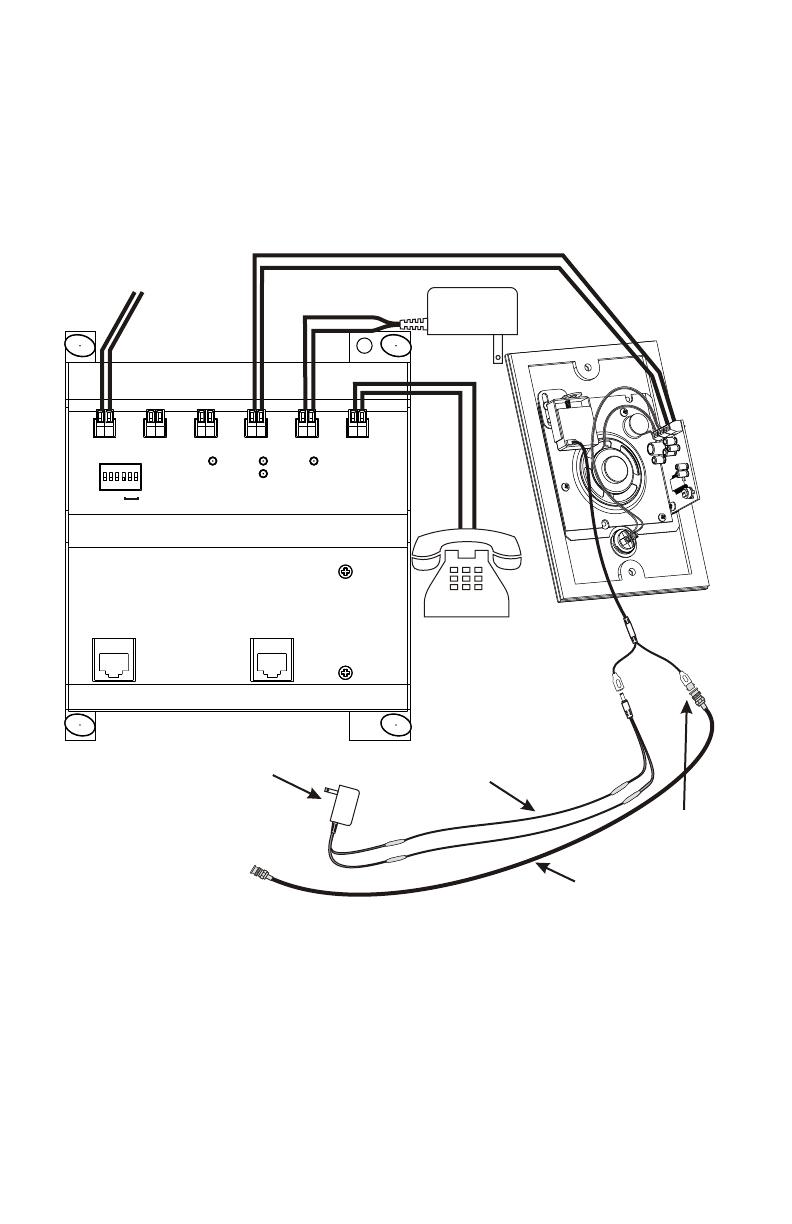
Installation:
Install a compatible mounting box at the desired location, such as:
h
Using a 2-conductor wire, connect the Telephone Entry Controller to
h
the empty screw terminal block on the DP (see diagram).
If necessary, attach the camera’s video output to a coax extension
h
that is long enough to reach your monitor or video distribution
equipment.
If necessary, cut the connector off of the end of the power supply and
h
splice in an extension using crimp-on connectors.
DP-Rbox-II flush mount box, DP-9001 surface mount box, or DP-9002
surface mount box.
Channel Vision’s DP-0xxx does not come with a camera, but the DP-5xxx &
DP-6xxx Series door plates come with mini cameras which attach to the
integrated camera mount. The DP-5xxx contains a Black & White camera,
while the DP-6xxx contains a color camera. The DP-0xxx, DP-5xxx, and DP-
6xxx all interface with the Channel Vision’s telephone entry controllers:
TE110, C-0920, P-0920 and P-0921 to provide audio and video
communication with the front door.
Channel Vision Compatible (DP-xxxx)
Camera Power
To Monitor or
Video Distribution
Coax Extension
(not included)
BNC Video
Connector
2-Conductor Power
Supply Extension
(not included)
Strike
Active
Ring
Intercom
Active
12VAC
#
or
*
No CO
Strike
Time
3/5 rng
1
2
3
PowerIntercomUnlock
Door
ChimeCO Input
Phones
TELEPHONE ENTRY CONTROLLER
CO Input
Telephones
Model
P-0920
PRO
C H A N N E L
TM
V I S I ON
C H A N N E L
V I S I ON
TM
Connect to the
terminals marked
“TO SYS”
From Telephone
Service Provider
House
Telephones
12VAC
500mA
8
9


