Page is loading ...

INSTRUCTION MANUAL
Read and understand all of the instructions and
safety information in this manual before operating
or servicing this tool.
52087824 REV1 © 2020 Greenlee Tools, Inc. 1/20
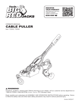
G10 Tugger™ Portable
Cable Puller and
PullingPackages
Español ............... 41
Français .............. 81

G10 Tugger™ Portable Cable Puller
Greenlee Tools, Inc. 4455 Boeing Dr. • Rockford, IL 61109-2988 USA • 815-397-7070
2
KEEP THIS MANUAL
Table of Contents
Safety Symbols ............................................................. 3
General Power Tool Safety Warnings .........................4–5
Work Area Safety ....................................................... 4
Electrical Safety ......................................................... 4
Personal Safety .......................................................... 4
Power Tool Use and Care .......................................4–5
Service ....................................................................... 5
Tool Specic Safety Information .................................6–8
Operational Hazards .................................................. 6
Setup Hazards ........................................................6–7
Electrical Hazards ...................................................... 8
Repairs and Modications ......................................... 8
Description .................................................................... 9
Identication .............................................................9–11
Specications .............................................................. 12
CABLE PULLER SETUP AND OPERATION
Boom Assembly/Disassembly ................................. 14
Boom Setup ........................................................ 15-18
Up Pull Starting from Teepee Position ................. 15
Down Pull Starting from Teepee Position ............. 16
Horizontal Pull ...................................................... 17
Single Boom Pull .................................................. 17
Boom Components .............................................. 18
Transporting the Boom ............................................ 19
Boom Operation .................................................20–21
Chain Mount Setup .............................................22–23
Floor Mount Setup ................................................... 24
Puller Operation ....................................................... 25
Removing Cable ...................................................... 26
CABLE PULLING PRINCIPLES
Cable Pulling Glossary ............................................. 28
Cable Pulling Principles ......................................29–37
Cable Pulling Systems ............................................. 29
Pulling Theory ...................................................... 30
Cable Pulling Forces ......................................31–35
Tailing the Rope .................................................... 36
Summary of Cable Pulling Principles ................... 37
Planning the Pull ...................................................... 37
Service and Maintenance ............................................ 38
FCC Certication ......................................................... 39
Warranty Information ................................................... 39
Illustration and Parts Lists
G10 Tugger™ ..................................................121–122
Mobile Carriage and Boom .............................123–124
Accessories ........................................................... 125

G10 Tugger™ Portable Cable Puller
Greenlee Tools, Inc. 4455 Boeing Dr. • Rockford, IL 61109-2988 USA • 815-397-7070
3
Safety Symbols
In this operator’s manual and on the product, safety
symbols and signal words are used to communicate
important safety information. This section is provided
toimprove understanding of these signal words
andsymbols.
This is the safety alert symbol. It is used to
alert you to potential personal injury
hazards. Obey all safety messages that
follow this symbol to avoid possible injury
ordeath.
DANGER
DANGER indicates a hazardous situation which, if not
avoided, will result in death or serious injury.
WARNING
WARNING indicates a hazardous situation which, if not
avoided, could result in death or serious injury.
This symbol means read the operator’s
manual carefully before using the
equipment. The operator’s manual contains
important information on the safe and
proper operation of the equipment.
This symbol means always wear safety
glasses with side shields or goggles when
handling or using this equipment to reduce
the risk of eye injury.
This symbol indicates the risk of hands,
ngers or other body parts being cut or
severed.
This symbol indicates the risk of
electricalshock.
This symbol means always wear protective
gloves when operating handling or operating
this equipment to reduce the risk of injury.
This symbol indicates a risk of ying debris.
This symbol indicates a risk of
fallingobjects.
This symbol means never operate this
equipment in a hazardous environment.
This symbol indicates a risk of injury from
rotating parts.
This symbol indicates a risk of crushing from a
rotating capstan.
This symbol indicates a risk of becoming
entangled in rope.
This symbol indicates a risk of unsecured
components moving unexpectedly.
This symbol means the operator must
disconnect the tool from the power supply.
This symbol means the tool must be properly
grounded to reduce the risk of electrical shock
to the operator.
This symbol means the tool must not be used
tolift or lower a load.

G10 Tugger™ Portable Cable Puller
Greenlee Tools, Inc. 4455 Boeing Dr. • Rockford, IL 61109-2988 USA • 815-397-7070
4
GENERAL POWER TOOL
SAFETYWARNINGS*
Read all safety warnings, instructions, illustrations
and specifications provided with this power tool.
Failure to follow all instructions listed below may result
in electric shock, re and/or serious injury.
* The text used in the General Power Tool Safety Warnings section of this manual is required
from the applicable UL 62841-1 standard to which this tool is tested. This section contains
general safety practices for many different types of power tools. Not every precaution
applies to every tool, and some may not apply to this tool.
SAVE ALL WARNINGS AND INSTRUCTIONS FOR
FUTURE REFERENCE.
The term "power tool" in the warnings refers to your
mains-operated (corded) power tool or BATTERY
operated (cordless) power tool.
WORK AREA SAFETY
Keep work area clean and well lit. Cluttered or dark
areas invite accidents.
Do not operate power tools in explosive
atmospheres, such as in the presence of flammable
liquids, gases or dust. Power tools create sparks
which may ignite the dust or fumes.
Keep children and bystanders away while operating
a power tool. Distractions can cause you to
losecontrol.
ELECTRICAL SAFETY
Power tool plugs must match the outlet. Never
modify the plug in any way. Do not use any adapter
plugs with earthed (grounded) power tools.
Unmodied plugs and matching outlets will reduce risk
of electric shock.
Avoid body contact with earthed or grounded
surfaces, such as pipes, radiators, ranges and
refrigerators. There is an increased risk of electric
shock if your body is earthed or grounded.
Do not expose power tools to rain or wet conditions.
Water entering a power tool will increase the risk of
electric shock.
Do not abuse the cord. Never use the cord for
carrying, pulling or unplugging the power tool. Keep
cord away from heat, oil, sharp edges or moving
parts. Damaged or entangled cords increase the risk of
electric shock.
When operating a power tool outdoors, use an
extension cord suitable for outdoor use. Use of
a cord suitable for outdoor use reduces the risk of
electricshock.
If operating a power tool in a damp location is
unavoidable, use a RESIDUAL CURRENT DEVICE
(RCD) protected supply. Use of an RCD reduces the
risk of electric shock.
Note: The term "RESIDUAL CURRENT DEVICE (RCD)"
may be replaced by the term "ground fault circuit
interrupter (GFCI)" or "earth leakage circuit breaker
(ELCB)"
PERSONAL SAFETY
Stay alert, watch what you are doing and use
common sense when operating a power tool. Do
not use a power tool while you are tired or under the
influence of drugs, alcohol or medication. A moment
of inattention while operating power tools may result in
serious personal injury.
Use personal protective equipment. Always wear
eye protection. Protective equipment such as dust
mask, non-skid safety shoes, hard hat, or hearing
protection used for appropriate conditions will reduce
personalinjuries.
Prevent unintentional starting. Ensure the switch is
in the off-position before connecting to power source
and or BATTERY pack, picking up or carrying the tool.
Carrying power tools with your nger on the switch
orenergizing power tools that have the switch on
invitesaccidents.
Remove any adjusting key or wrench before turning
the power tool on. A wrench or a key left attached
to arotating part of the power tool may result in
personalinjury.
Do not overreach. Keep proper footing and balance
at all times. This enables better control of the power
tool in unexpected situations.
Dress properly. Do not wear loose clothing or
jewelry. Keep your hair, clothing and gloves away
from moving parts. Loose clothes, jewelry or long hair
can be caught in moving parts.
If devices are provided for the connection of dust
extraction and collection facilities, ensure these are
connected and properly used. Use of dust collection
can reduce dust-related hazards.
Do not let familiarity gained from frequent use of
tools allow you to become complacent and ignore
tool safety principles. A careless action can cause
severe injury within a fraction of a second.
POWER TOOL USE AND CARE
Do not force the power tool. Use the correct power
tool for your application. The correct power tool
will do the job better and safer at the rate for which it
wasdesigned.
WARNING

G10 Tugger™ Portable Cable Puller
Greenlee Tools, Inc. 4455 Boeing Dr. • Rockford, IL 61109-2988 USA • 815-397-7070
5
Do not use the power tool if the switch does not turn
it on and off. Any power tool that cannot be controlled
with the switch is dangerous and must be repaired.
Disconnect the plug from the power source and/
or remove the BATTERY pack, if detachable, from
the power tool before making any adjustments,
changing accessories, or storing power tools. Such
preventive safety measures reduce the risk of starting
the power tool accidentally.
Store idle power tools out of the reach of children
and do not allow persons unfamiliar with the power
tool or these instructions to operate the power
tool. Power tools are dangerous in the hands of
untrainedusers.
Maintain power tools and accessories. Check for
misalignment or binding of moving parts, breakage
of parts and any other condition that may affect the
power tool’s operation. If damaged, have the power
tool repaired before use. Many accidents are caused by
poorly maintained power tools.
Keep cutting tools sharp and clean. Properly
maintained cutting tools with sharp cutting edges are
less likely to bind and are easier to control.
Use the power tool, accessories and tool bits etc.
in accordance with these instructions, taking into
account the working conditions and the work to
be performed. Use of the power tool for operations
different from those intended could result in a hazardous
situation.
Keep handles and grasping surfaces dry, clean
and free from oil and grease. Slippery handles and
grasping surfaces do not allow for safe handling and
control of the tool in unexpected situations.
SERVICE
Have your power tool serviced by a qualified repair
person using only identical replacement parts.
Thiswill ensure that the safety of the power tool
ismaintained.

G10 Tugger™ Portable Cable Puller
Greenlee Tools, Inc. 4455 Boeing Dr. • Rockford, IL 61109-2988 USA • 815-397-7070
6
TOOL SPECIFIC SAFETY
INFORMATION
This section contains important safety information
that is specic to this tool.
Read these precautions carefully before using the
tool to reduce the risk of electrical shock or serious
personal injury.
Improper operation or service presents a risk of
serious injury or death from electric shock, arc ash,
thermal burns, cutting, crushing, and other hazards.
SAVE THESE INSTRUCTIONS!
A compartment in the tool carrying case is
includedto keep this manual with the tool to
reference before each operation.
Operational Hazards
Wear eye protection when using this tool.
Eye injury could result from ying debris.
Wear protective gloves when handling
pulling rope.
Do not allow anything other than the rope
to contact the capstan. Any inline pulling
component other than rope such as a cable
grip or swivel could break and send debris
ying with great force.
Do not allow any unnecessary personnel
to remain in the area of the tool during
operation. Do not allow personnel to
stand in line with the pulling rope
Rope,
cable and any connecting device can
break under tension causing the rope to y
aroundviolently.
Keep hands away from capstan.
Your
ngers and hands can be crushed, fractured
or amputated if they become caught
between the rope and the capstan.
Do not allow the rope to become overlapped on the
capstan.
If an overlap occurs, relax the tailing force and
immediately shut off the cable puller.
Keep hands away from capstan.
• Do not wrap rope around hands, arms,
waist or other body parts.
• Do not stand in spent coils or tailed rope.
Hold rope so that it may be released
quickly.
• Do not operate the cable puller while
wearing loose-tting clothing.
• Retain long hair.
• Entanglement in rope could result in
severe injury or death.
Do not stand directly under a vertical pull.
Cable could fall suddenly from
theconduit.
Use this tool for the manufacturer’s intended
purpose only. Do not use the cable puller as
a winch or hoist.
• The cable puller cannot lower a load.
• The load may fall.
Setup Hazards
GENERAL SETUP
Inspect and verify the maximum load-
bearing capacity or maximum strength
of all structural supports, pulling system
components, and anchoring systems
before setting up the puller. All pulling
system components must have a
maximum load rating equal to or greater
than the maximum load rating of the
cable puller. Any component that does not
meet the load rating of the system could
break and result in ying debris.
Inspect puller and accessories for wear and
damage before use. Replace any worn
or damaged components with Greenlee
replacement parts. A damaged, worn or
improperly assembled item could break and
result in ying debris.
Use a double-braided composite rope with
the following minimum characteristic:
Average breaking strength:
atleast143 kN (32,000 lb)
Check the condition of the entire rope
before use. A worn, damaged or undersized
rope could break under tension and result in
ying debris.
WARNING

G10 Tugger™ Portable Cable Puller
Greenlee Tools, Inc. 4455 Boeing Dr. • Rockford, IL 61109-2988 USA • 815-397-7070
7
Attach the pulling rope to the cable with
appropriate types of connectors. Select
connectors with a maximum rated
capacity of 4.5 kN (10,000 lb). An under-
rated connector could break under tension
and result in ying debris.
Set up the cable puller so that the rope will
approach the capstan at an angle of 90°
(±5°). Angles outside of this range could
cause the rope to overlap.
BOOM SETUP
Always lock boom components in place
during assembly or disassembly.
Unsecured components could move
unexpectedly when maneuvering the boom.
Never place fingers through holes in
boom components.
Always keep elbow
unit locked with pivot pin except while
adjusting. Rotating parts could cut
offngers.
Use only Greenlee supplied booms or
straight 3” diameter rigid steel conduit or
schedule 40 steel pipe for the boom tubes.
Do not use boom tubes longer than
3meters (10’). Longer booms could bend
and break.
BOOM TRANSPORTATION
When using the wheeled carriage to
transport the G10:
• Keep personnel out of the path
oftransport
• Evaluate the terrain over which the
carriage is to move. If in doubt, obtain
additional help and move the carriage
slowly.
• Do not transport over inclines of more
than 15°.
• Do not transport the carriage with boom
tubes longer than the supplied 3’ and 4’
boom tubes.
CHAIN MOUNT SETUP
Install vise chains properly.
• Follow the vise chain tightening
instructions carefully. Improperly
tightened chains can allow the puller
toslide or break loose and strike
nearbypersonnel.
• Do not mount the chain mount to steel
conduit less than 63.5 mm (2-1/2”) in
diameter. This will not support the loads
imposed by the puller.
• Do not mount the chain mount to PVC
conduit of any size. This will not support
the loads imposed by the puller.
• Do not setup the vice chains on a
structural support that is less than
51 mm (2”) or more than 254 mm (10”)
wide. Mounting to an undersized or
oversized structural support can allow the
puller to slide or break loose and strike
nearby personnel.
• Do not allow the vise chains to bind at
the corners when mounting the puller
to a square or rectangular support.
Thevice chains must be uniformly tight at
all points.
FLOOR MOUNT SETUP
Install the oor mount anchors properly.
• Follow all oor mounting instructions
carefully. An improperly attached oor
mount can come loose and strike nearby
personnel.
• Do not attach the oor mount to masonry,
brick or cinder block. These materials will
not hold the anchors securely.
• If any of the four anchors spin before the
minimum torque is achieved, abandon the
location and start elsewhere. An improperly
installed anchor can allow the puller to
break loose.

G10 Tugger™ Portable Cable Puller
Greenlee Tools, Inc. 4455 Boeing Dr. • Rockford, IL 61109-2988 USA • 815-397-7070
8
Electrical Hazards
Disconnect the cable puller from the
power supply before servicing.
This tool must be grounded.
In the event of
a malfunction or breakdown, an electrical
ground provides a path of least resistance
for the electric current. This path of least
resistance is intended to reduce the risk of
electric shock to the operator.
This tool’s electric cord has a grounding
conductor and a grounding plug as shown.
Do not modify the plug.
Connect the plug
to a corresponding GFCI-protected
receptacle that is properly installed and
grounded in accordance with all national
andlocal codes and ordinances.
Do not
usean adapter.
20 Amp / 115 Volt Plug and Grounded Receptacle
Plug Receptacle
Repairs and Modifications
Repairs should only be performed by qualied repair
technicians. Modications of any kind to the tool are not
allowed. Unauthorized repairs and modications can
result in a tool that is unsafe to operate.
ReceptaclePlug

G10 Tugger™ Portable Cable Puller
Greenlee Tools, Inc. 4455 Boeing Dr. • Rockford, IL 61109-2988 USA • 815-397-7070
9
Description
The Greenlee G10 Tugger™ Portable Cable Puller is
intended to be used to pull cable through conduit and in
tray. The G10 Tugger™ will develop 44.5 kN (10,000 lb)
of pulling force. Refer to a Greenlee catalog for sheaves,
pulling rope, and other cable pulling accessories to
create an entire cable pulling system.
No single manual can provide instructions for every
possible cable pulling application; this manual contains
general information necessary to accomplish cable
pulls setup with the boom mount, oor mount and
chain mount. This tool should only be operated by
appropriately trained professionals.
Safety
Safety is essential in the use and maintenance of
Greenlee tools and equipment. This instruction manual
and any markings on the tool provide information
for avoiding hazards and unsafe practices related
to the use of this tool. Observe all of the safety
informationprovided.
Identification
G10 Cable Puller
1. Motor
2. Force Gauge
3. Foot Switch Jack
4. Adjustable Sheave Bar
5. Hitch Clip
6. Rope Tie-Off
7. Rope Ramp
8. Mounting Plates
9. On/Off Switch
10. Circuit Breaker
11. Removable Power
12. Control Box
13. Gearbox
14. Tapered Steel Capstan
15. Right Angle Sheave
Purpose of this Manual
This manual is intended to familiarize all personnel with
the safe operation and maintenance procedures for the
Greenlee G10 Tugger™ Portable
Cable Puller.
Keep this manual available to all personnel.
Replacement manuals are available upon request at no
charge at www.greenlee.com.
All specications are nominal and may change as design
improvements occur. Greenlee Tools, Inc. shall not be liable for
damages resulting from misapplication or misuse of its products.
2
8
7
9
10
11
12
13
6
5
4
3
1
15
14

G10 Tugger™ Portable Cable Puller
Greenlee Tools, Inc. 4455 Boeing Dr. • Rockford, IL 61109-2988 USA • 815-397-7070
10
Identification (cont’d)
Mobile Carriage
andBoom
1. Puller
2. Elbow
3. Nose
4. Back Boom
5. Forward Boom
6. Detent Pin
7. Crank
8. Conduit Adapter
Couplings
9. Adapter Storage
Hanger
10. Storage Tray
11. Brake
12. Swivel Caster
13. Transport Handle
14. Boom Mount
15. Ring Pull Detent Pin
16. Location for
Additional Adapter
Storage Racks
6
1
7
3
2
11
10
12
5
4
13
3
16
15
15
14
8
9

G10 Tugger™ Portable Cable Puller
Greenlee Tools, Inc. 4455 Boeing Dr. • Rockford, IL 61109-2988 USA • 815-397-7070
11
Identification (cont’d)
Chain Mount
andFloorMount
1. Puller
2. Chain Mount Frame
3. Vise Chain Handle
4. Vise Chain
5. Conduit
6. Floor Mount Frame
7. Anchors
Chain Mount—Secured to Steel Conduit or Pipe
Floor Mount—Secured to a Concrete Floor
1
4
5
3
2
1
7
6

G10 Tugger™ Portable Cable Puller
Greenlee Tools, Inc. 4455 Boeing Dr. • Rockford, IL 61109-2988 USA • 815-397-7070
12
Specifications
Weight (G10 Tugger™ only) .................................................................. 45.4 kg (100 lb)
Dimensions
Length ................................................................................................. 29 cm (11.5")
Width .................................................................................................... 76.2 cm (30")
Height ...................................................................................................... 33 cm (13")
Motor
Voltage .......................................................................120 VAC, 60 Hz, single phase
Current Draw at Full Load ............................................................... 20 amps (120 V)
Power Source ................................................. 120 VAC, 60 Hz, 20 amps, single phase
Speed LOW HIGH
No Load ....................................... 4.1 m/min (13.5 ft/min) 6.8 m/min (22.4 ft/min)
8900 N (2000 lb) ........................... 3.9 m/min (12.75 ft/min) 6.4 m/min (21 ft/min)
17.8 kN (4000 lb) .......................... 3.8 m/min (12.4 ft/min) 4.9 m/min (16.1 ft/min)
26.7 kN (6000 lb) .......................... 3.7 m/min (12.1 ft/min) —
35.6 kN (8000 lb) .......................... 2.7 m/min (9 ft/min) —
Pulling Force
0 kN to 28.9 kN (0 lb to 8000 lb) .............................................Continuous operation
35.6 kN to 44.5 kN (8000 lb to 10,000 lb) ............................................... Momentary
Pulling Rope
Required Rope ....................... 7/8" diameter, double-braided, polyester composite
Average Breaking Strength .......................................... 143 kN (32,000 lb) minimum
13

G10 Tugger™ Portable Cable Puller
Greenlee Tools, Inc. 4455 Boeing Dr. • Rockford, IL 61109-2988 USA • 815-397-7070
13
Cable Puller Setup
and Operation

G10 Tugger™ Portable Cable Puller
Greenlee Tools, Inc. 4455 Boeing Dr. • Rockford, IL 61109-2988 USA • 815-397-7070
14
Boom Assembly/Disassembly
Under normal circumstances, there is no need to
disassemble the boom assembly. However, it can be
disassembled in order to t into a small truck, mount the
puller head remotely on a oor mount, alter the boom
lengths, etc.
To disassemble, follow this procedure:
1. Lock the swivel caster brakes.
2. Pivot the elbow until the forward boom is clear of
the carriage.
3. Grab the nose by the hole at the end of the boom
tube, and lift up to relieve the preload on the detent
pins.
Ring Pull
Detent Pin
Grab
Point
4. Pull out on the detent ring that locks the boom tube,
and twist the nose slightly so the hole in the boom
tube and detent pin are misaligned.
5. Release the detent ring, and pull the nose and
forward boom from the elbow.
6. Repeat this process to remove the back boom
and elbow. Raise or lower the boom(s) as desired
beforehand to gain a comfortable position.
7. Turn the crank clockwise until the puller head is as
high as it will go.
8. Remove the clips and pull out the pins that mount
the puller head.
9. Lift the puller head off the boom mount using as
many people as needed to lift 45 kg (100 lb).
Aside from detaching the other end of the two boom
tubes, this is as far as the unit breaks down. Assemble
in the reverse order, making sure that all detent pins are
fully seated before releasing your hold.
Ring Pull
Detent Pin
Grab
Point
Puller
Mounting
Pins
Ring Pull
Detent Pin

G10 Tugger™ Portable Cable Puller
Greenlee Tools, Inc. 4455 Boeing Dr. • Rockford, IL 61109-2988 USA • 815-397-7070
15
Boom Setup
Up Pull Starting from Teepee Position
1. Set the brakes.
2. Raise the forward boom as described under “Boom
Operation” until it is close to the angle desired for
the pull setup,
or
a. Lock the elbow detent pins in the fully inward
position.
b. Lower the boom (turn crank CW) until the nose
hits the oor.
c. Release the brakes and continue to lower the
boom while walking the carriage backwards
until the elbow is at the desired angle and lock it
in place.
Position Elbow to Desired Angle
3. Raise or lower the boom until the nose is just above
the conduit to be pulled from.
Conduit
Position Nose Higher than Conduit
To use slip-in couplings:
a. Insert the appropriate slip-in conduit adapter
coupling into the nose.
b. Pivot the nose until the coupling is aligned with
the conduit and lock in position.
c. Raise the boom until the bottom of the coupling
clears the conduit.
d. Release the brakes if not already released.
e. Roll the carriage forward until the coupling is
over the conduit and lower it into the conduit.
To use screw-on couplings:
a. Screw the appropriate screw-on adapter
coupling fully onto the conduit.
b. Pivot the nose until it is aligned with the
coupling and lock in position.
c. Raise the boom until the bottom of the coupling
clears the conduit.
d. Release the brakes if not already released.
e. Roll the carriage forward until the nose is over
the coupling, pull the detent ring, and lower the
nose onto the coupling.
Insert Conduit Adapter and Raise above Conduit
Lower into Conduit
Conduit

G10 Tugger™ Portable Cable Puller
Greenlee Tools, Inc. 4455 Boeing Dr. • Rockford, IL 61109-2988 USA • 815-397-7070
16
Boom Setup (cont’d)
Down Pull Starting from Teepee Position
1. Set the brakes.
2. Pivot the elbow one or two detent positions
outward. Lift up on the nose to release any preload
on the detent pin securing the back boom to the
elbow.
3. While holding the detent out, rotate the elbow
on the back boom 180° by walking it around the
carriage.
4. Lower the entire boom until the forward boom is
close to vertical.
5. Lower the forward boom until the elbow is close to
the angle desired for the pull setup.
6. Raise or lower the boom until the nose is just below
the conduit to be pulled from.
To use slip-in couplings:
a. Insert the appropriate slip-in conduit adapter
coupling into the nose.
b. Pivot the nose until the coupling is aligned with
the conduit and lock in position.
c. Lower the boom until the coupling clears the
conduit.
d. Release the brakes.
e. Roll the carriage forward until the coupling is
under the conduit and raise it.
To use screw-on couplings:
a. Screw the appropriate screw-on adapter
coupling fully onto the conduit.
b. Pivot the nose until it is aligned with the
coupling and lock in position.
c. Lower the boom until the coupling clears the
conduit.
d. Release the brakes.
e. Roll the carriage forward until the nose is under
the coupling, pull the detent ring, and raise the
nose onto the coupling.
Use caution when transporting or adjusting the
boom in an extended state, weight may shift
suddenly resulting in a tipping hazard.
Typical Down Pull Setup
WARNING
Rotate 180°

G10 Tugger™ Portable Cable Puller
Greenlee Tools, Inc. 4455 Boeing Dr. • Rockford, IL 61109-2988 USA • 815-397-7070
17
Boom Setup (cont’d)
Horizontal Pull
Horizontal pulls are essentially the same as an up pull or
a down pull.
• If the conduit is above the puller, follow the up pull
instructions.
• If the conduit is below the puller, follow the down pull
instructions.
The only difference is in the horizontal alignment of the
coupling with the conduit and using the carriage to
walk the coupling into the conduit (or the nose into the
coupling for the screw-on adapters).
Horizontal Pull in Underground Vault
Single Boom Pull
All of the previous boom setup instructions assume that
two booms are used. While using two booms can be
useful for working around obstructions, keeping angles
over sheaves to a minimum, and pulling out extra tail,
it is not always necessary. A single 3', 4', or 3" rigid
conduit up to 10' long can be used to keep setups even
simpler.
Single Boom Setup

G10 Tugger™ Portable Cable Puller
Greenlee Tools, Inc. 4455 Boeing Dr. • Rockford, IL 61109-2988 USA • 815-397-7070
18
Boom Components
Use these boom tubes only:
• Boom tubes supplied with the G10
• 3" rigid steel conduit (3 m or 10' maximum)
• 3" Schedule 40 pipe (3 m or 10' maximum)
If using 3" rigid conduit in place of the standard booms:
1. Insert the conduit while pulling out the detent rings.
2. Slide the conduit fully in and verify it is seated
through the sight holes.
3. Use 1/2"-13 screws (not supplied) in the weld nuts
to lock the conduit in place.
Sight Holes
Detent Rings
Boom Setup (cont’d)
Sight Holes
Detent Rings

G10 Tugger™ Portable Cable Puller
Greenlee Tools, Inc. 4455 Boeing Dr. • Rockford, IL 61109-2988 USA • 815-397-7070
19
Transporting the Boom
Wheeling
1. If the unit had been set up for an up pull:
a. Lower the nose to the oor to get to the Teepee
transport position.
b. Lock the elbow pivot detents in the inward
position.
c. Raise the boom by cranking until the nose is off
the oor, and release the detents.
If the unit had been set up for a down pull:
a. Release the elbow pivot detents, fold the
forward boom back to the next to last position,
and lock the elbow.
b. Raise the boom all the way up until it hits the
stop.
c. Release the ring pull detent that locks the back
boom to the elbow, and rotate the elbow 180°
into its Teepee position.
2. Lift the push/pull handle up until it contacts the
boom mount to push the carriage. Use the same
handle to pull the unit.
Handle Position for Pushing
Handle raised
for pulling
Handle Position for Pulling
3. Fold the handle down on top of the puller head
when not in use to keep it out of the way.
Lifting
1. Connect a lifting sling to the top puller head
mounting pin.
2. Feed the sling up between the sheave and frame of
the elbow so that it is trapped.
3. Lift the sling from above the elbow.
Sling
Handle raised
for pulling
Handle raised
for pulling

G10 Tugger™ Portable Cable Puller
Greenlee Tools, Inc. 4455 Boeing Dr. • Rockford, IL 61109-2988 USA • 815-397-7070
20
Boom Operation
Raising and Lowering
The boom can be raised and lowered using the crank
in front of the puller. Turn the crank counterclockwise to
raise the boom, and clockwise to lower it. When starting
from the Teepee position, unlock the elbow before
lowering to prevent the boom from crashing against the
carriage.
Teepee Position
Pivoting the Elbow and Nose Units
The elbow and nose units are physically identical and
can be used interchangeably. For the sake of clarity, in
this manual:
• “Nose” refers to the unit that attaches to the conduit
via couplers.
• “Elbow” refers to the unit that connects the two boom
tubes.
The elbow/nose units pivot and lock at various degrees
of rotation. They are locked in place by a detent pin set
located between the sheave and the end of the boom
tube receptacle. To pivot, squeeze the grips on the
detent pins fully inward.
Make sure the detent pins on both sides are fully
retracted before trying to pivot. Release the grips when
the desired pivot angle is reached, and pivot slightly
more to allow both detents to engage in the closest
holes.
When the detent pins are squeezed to the fully inward
position, they can be locked in place by twisting them
counterclockwise.
Never pull cable with the detent pins locked inward;
both the elbow and nose must be locked from pivoting
before pulling.
Grips
Squeeze
Twist to lock.
/