Page is loading ...

IMPORTANT: Read and understand this manual before assembling, starting or servicing
heater. Improper use of heater can cause serious injury. Keep this manual for future reference.
150,000 Btu/Hr
with Built-in
Thermostat
PROPANE CONSTRUCTION
FORCED AIR HEATER
OWNER’S MANUAL
Save this manual for future reference.
Save this manual for future reference.
For more information, visit www.desatech.com
For more information, visit www.desatech.com
GENERAL HAZARD WARNING:
FAILURE TO COMPLY WITH THE PRECAUTIONS AND INSTRUCTIONS PROVIDED WITH THIS
HEATER, CAN RESULT IN DEATH, SERIOUS BODILY INJURY AND PROPERTY LOSS OR
DAMAGE FROM HAZARDS OF FIRE, EXPLOSION, BURN, ASPHYXIATION, CARBON MONOX-
IDE POISONING, AND/OR ELECTRICAL SHOCK.
ONLY PERSONS WHO CAN UNDERSTAND AND FOLLOW THE INSTRUCTIONS SHOULD USE
OR SERVICE THIS HEATER.
IF YOU NEED ASSISTANCE OR HEATER INFORMATION SUCH AS AN INSTRUCTIONS
MANUAL, LABELS, ETC. CONTACT THE MANUFACTURER.
TABLE OF CONTENTS
SAFETY INFORMATION ............................................................ 2
PRODUCT IDENTIFICATION ..................................................... 3
UNPACKING ............................................................................... 3
THEORY OF OPERATION ......................................................... 3
PROPANE SUPPLY .................................................................... 4
INSTALLATION ........................................................................... 4
VENTILATION............................................................................. 5
OPERATION ............................................................................... 5
STORAGE................................................................................... 5
MAINTENANCE .......................................................................... 5
SERVICE PROCEDURES .......................................................... 6
SPECIFICATIONS ...................................................................... 7
WIRING DIAGRAMS................................................................... 7
ILLUSTRATED PARTS BREAKDOWN AND PARTS LIST ......... 8
ACCESSORIES ........................................................................ 10
TECHNICAL SERVICE ............................................................. 10
REPLACEMENT PARTS .......................................................... 10
OWNER'S REGISTRATION ......................................................11
WARRANTY INFORMATION......................................Back Cover
RLP155AT

111855-01A
2
For more information, visit www.desatech.com
For more information, visit www.desatech.com
WARNINGS
WARNING: This product contains and/or generates
chemicals known to the State of California to cause
cancer or birth defects, or other reproductive harm.
WARNING: FIRE, BURN, INHALATION, AND EX-
PLOSION HAZARD. KEEP SOLID COMBUSTIBLES,
SUCH AS BUILDING MATERIALS, PAPER OR CARD-
BOARD, A SAFE DISTANCE AWAY FROM THE
HEATER AS RECOMMENDED BY THE INSTRUC-
TIONS. NEVER USE THE HEATER IN SPACES WHICH
DO OR MAY CONTAIN VOLATILE OR AIRBORNE
COMBUSTIBLES, OR PRODUCTS SUCH AS GASO-
LINE, SOLVENTS, PAINT THINNER, DUST PARTICLES
OR UNKNOWN CHEMICALS.
WARNING: NOT FOR HOME OR RECREATIONAL
VEHICLE USE.
The heater is designed for use as a construction heater in accordance
with ANSI Z83.7/CGA2.14. Other standards govern the use of fuel
gases and heating products for specific uses. Your local authority can
advise you about these. The primary purpose of construction heaters is
to provide temporary heating of buildings under construction, alteration
or repair. Properly used, the heater provides safe economical heating.
Products of combustion are vented into the area being heated.
We cannot foresee every use which may be made of our heaters.
Check with your local fire safety authority if you have questions
about heater use.
Other standards govern the use of fuel gases and heat producing products
for specific uses. Your local authorities can advise you about these.
Carbon Monoxide Poisoning: Some people are more affected by
carbon monoxide than others. Early signs of carbon monoxide
poisoning resemble the flu, with headaches, dizziness, and/or nau-
sea. If you have these signs, the heater may not be working properly.
Get fresh air at once! Check for proper ventilation and have heater
serviced.
Propane Gas: Propane gas is odorless. An odor-making agent is
added to propane gas. The odor helps you detect a propane gas leak.
However, the odor added to propane gas can fade. Propane gas may
be present even though no odor exists.
Make certain you read and understand all warnings. Keep this
manual for reference. It is your guide to safe and proper operation
of this heater.
• This product has been approved for use in the Commonwealth of
Massachusetts.
SAFETY INFORMATION
SAFETY INFORMATION
• Install and use heater with care. Follow all local ordinances and codes.
In the absence of local ordinances and codes, refer to the Standard
for Storage and Handling of Liquefied Petroleum Gas, ANSI/NFPA
58 and the Propane Gas Installation Code, CAN/CGA B149.2. This
instructs on the safe storage and handling of propane gases.
• Use only the electrical voltage and frequency specified on model
plate. The electrical connections and grounding of the heater shall
follow the National Electric Code, ANSI/NFPA 70 or the Canadian
Electrical Code, Part 1.
• Electrical grounding instructions — This appliance is equipped with
a three-prong (grounding) plug for your protection against shock
hazard and should be plugged directly into a properly grounded
three-prong receptacle or extension cord.
• Use only the hose and factory preset regulator provided with the heater.
• Use only propane gas set up for vapor withdrawal.
• Provide adequate ventilation. Before using heater, provide at least a
three-square-foot opening of fresh, outside air for each 100,000 Btu/Hr
(105,500 k/j) of rating.
• For indoor use only. Do not use heater outdoors.
• Do not use heater in occupied dwellings or in living or sleeping quarters.
• Do not use heater in a basement or below ground level. Propane gas
is heavier than air. If a leak occurs, propane gas will sink to the
lowest possible level.
• Keep appliance area clear and free from combustible materials, gaso-
line, paint thinner, and other flammable vapors and liquids. Dust is
combustible. Do not use heater in areas with high dust content.
• Minimum heater clearances from combustible materials:
Outlet: 8 Ft.(2.4 m) Sides: 2 Ft.(.6 m) Top: 6 Ft.(1.8 m) Rear: 2 Ft.(.6 m)
• Keep heater at least six feet from propane tank(s). Do not point
heater at propane tank(s) within 20 feet (6.1 m).
• Keep propane tank(s) below 100° F (38° C).
• Check heater for damage before each use. Do not use a damaged heater.
• Check hose before each use of heater. If highly worn or cut, replace
with hose specified by manufacturer before using heater.
• Locate heater on stable and level surface if heater is hot or operating.
• Never block air inlet (rear) or air outlet (front) of heater.
• Keep heater away from strong drafts, wind, water spray, rain, or
dripping water.
• Keep children and animals away from heater.
• This heater is equipped with a thermostat. Heater may start at anytime.
• Never move, handle, or service a hot or operating heater. Severe
burns may result. You must wait 15 minutes after turning heater off.
• To prevent injury, wear gloves when handling heater.
• Never attach duct work to heater.
• Do not alter heater. Keep heater in its original state.
• Do not use heater if altered.
• Turn off propane supply to heater and unplug heater when not in use.
• Use only original replacement parts. This heater must use design-
specific parts. Do not substitute or use generic parts. Improper re-
placement parts could cause serious or fatal injuries.

111855-01A
3
3
For more information, visit www.desatech.com
For more information, visit www.desatech.com
PRODUCT IDENTIFICATION
UNPACKING
THEORY OF OPERATION
Hot Air
Outlet
(Front)
Upper Shell
On/Off
Switch
Power Cord
Hose/Regulator
Assembly
Inlet
Connector
Lower Shell
Thermostat Knob
PRODUCT IDENTIFICATION UNPACKING
1. Remove all packing items applied to heater for shipment. Keep
plastic cover caps (attached to inlet connector and hose/regu-
lator assembly) for storage.
2. Remove all items from carton.
3. Check all items for shipping damage. If heater is damaged,
promptly inform dealer where you bought heater.
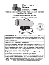
THEORY OF OPERATION
The Fuel System: The hose/regulator assembly attaches to the
propane gas supply. The propane gas moves through the solenoid
valve and out the nozzle.
The Air System: The motor turns the fan. The fan pushes air into
and around the combustion chamber. This air is heated and provides
a stream of clean, hot air.
The Ignition System: The direct spark ignitor (DSI) sends voltage
to the spark plug/ignitor. The spark plug/ignitor ignites the fuel and
air mixture.
The Safety Control System: This system causes the heater to shut
down if the flame goes out.
Air For Combustion Fuel
Combustion Chamber
Ignitor
Figure 2 - Cross Section Operational View
Clean
Heated
Air Out
(Front)
Cool
Air In
(Back)
Fan
Motor
Power
Cord
Hose/Regulator
Assembly
Solenoid
Valve
On/Off Switch
Air For Combustion
And Heating
Fuel
DSI
Nozzle
Figure 1 - 150,000 Btu/Hr Model
Handle
Fan Guard

111855-01A
4
For more information, visit www.desatech.com
For more information, visit www.desatech.com
PROPANE SUPPLY
INSTALLATION
PROPANE SUPPLY
Propane gas and propane tank(s) are to be furnished by the user.
Use this heater only with a propane vapor withdrawal supply
system. See Chapter 5 of the Standard for Storage and Handling of
Liquefied Petroleum Gas, ANSI/NFPA 58. Your local library or fire
department will have this booklet.
The amount of propane gas ready for use from propane tanks varies.
Two factors decide this amount:
1. The amount of propane gas in tank(s)
2. The temperature of tank(s)
The chart below shows the number of 100 pound (45 kg) tanks
needed to run this heater.
Do not operate this product with any tank smaller than 100 pounds.
Temperature °F (°C) Number of tanks
at tank location (150,000 Btu/Hr)
32 (0) 2
20 (-7) 2
10 (-12) 3
0 (-18) 3
-10 (-23) (Use larger
-20 (-29) tank)
Less gas is vaporized at lower temperatures. You may need two or
more 100 pound (45 kg) tanks or one larger tank in colder weather.
Your local propane gas dealer will help you select the proper supply
system. The minimum surrounding-air temperature rating for each
heater is -20°F (-29°C).
INSTALLATION
WARNING: Review and understand the warnings
in the
Safety Information
section, page 2. They are
needed to safely operate this heater. Follow all local
codes when using this heater.
WARNING: Test all gas piping and connections
for leaks after installing or servicing. Never use an
open flame to check for a leak. Apply a mixture of
liquid soap and water to all joints. Bubbles forming
show a leak. Correct all leaks at once.
1. Provide propane supply system (see Propane Supply, above).
2. Connect POL fitting on hose/regulator assembly to propane
tank(s). Turn POL fitting counterclockwise into threads on
tank. Tighten firmly using wrench. Tighten regulator with
vent pointing down.
Figure 4 - Hose and Inlet Connector
Hose
Inlet Connector
Figure 3 - Regulator With Vent Pointing Down
Propane
Tank
Hose
Regulator
Vent
(pointing down)
POL Fitting
Supply
Valve
3. Connect hose to inlet connector. Tighten firmly using a wrench.
IMPORTANT:
Extra hose or piping may be used if needed.
Install extra hose or piping between hose/regulator assembly
and propane tank. You must use the regulator supplied with
heater.
4. Open propane supply valve on propane tank(s) slowly.
Note:
If not opened slowly, excess-flow check valve on
propane tank may stop gas flow. If this happens, close pro-
pane supply valve and open again slowly.
5. Check all connections for leaks.
WARNING: Never use an open flame to check for
a leak. Apply a mixture of liquid soap and water to all
joints. Bubbles forming show a leak. Correct all
leaks at once.
6. Close propane supply valve.

111855-01A
5
5
For more information, visit www.desatech.com
For more information, visit www.desatech.com
VENTILATION
WARNING: Follow the minimum fresh, outside air
ventilation requirements. If proper fresh, outside air
ventilation is not provided, carbon monoxide poison-
ing can occur. Provide proper fresh, outside air ven-
tilation before running heater.
Provide a fresh air opening of at least three square feet for each
100,000 Btu/Hr (105,500 k/j)rating. Provide extra fresh air if more
heaters are being used.
VENTILATION
OPERATION
STORAGE
MAINTENANCE
OPERATION
WARNING: Review and understand the warnings
in the
Safety Information
section, page 2. They are
needed to safely operate this heater. Follow all local
codes when using this heater.
TO START HEATER
1. Follow all installation, ventilation and safety information.
2. Locate heater on stable and level surface. Make sure strong
drafts do not blow into front or rear of heater.
3. Plug power cord of heater into a three-prong, grounded exten-
sion cord. Extension cord must be at least six feet long. Exten-
sion cord must be UL listed.
Extension Cord Size Requirement
Up to 50 feet (15 m) long, use 18 AWG rated cord.
51 to 100 feet (15.5 to 30.5 m) long, use 16 AWG rated cord.
101 to 200 feet (30.78 to 61 m) long, use 14 AWG rated cord.
4. Plug extension cord into a 120 volt/60 hertz, three-hole,
grounded outlet.
5. Open propane supply valve on propane tank(s) slowly.
Note:
If not opened slowly, excess-flow check valve on pro-
pane tank may stop gas flow. If this happens, close propane
supply valve and open again slowly.
6. Turn thermostat control knob fully counterclockwise to the
"COOLER" position. Turn ON/OFF switch to the ON posi-
tion. Turn thermostat control knob slowly clockwise until elec-
tric motor and fan begin to run. Heater will start in approxi-
mately 3 seconds. Adjust thermostat control knob to WARMER
or COOLER setting as needed.
Note:
If heater does not start after 3 seconds, the ignition con-
trol will automatically attempt to start heater one time. If heater
fails to start on this attempt, the safety control will "lock out"
and no further automatic restarts will be attempted. This could
occur if air remains in fuel line. If heater fails to start on this
attempt, turn ON/OFF switch to OFF position. Wait ten sec-
onds for safety control to reset, then turn ON/OFF switch back
to ON position and try to start heater again.
7. Thermostat Operation Only: During normal thermostat op-
eration, heater will cycle off when air temperature rises to ther-
mostat setting. When air temperature drops sufficiently below
thermostat setting, the electric motor and fan will begin to run.
After 15 to 60 seconds, heater burner should automatically
ignite and provide heat to maintain temperature setting.
TO STOP HEATER
1. Tightly close propane supply valve on propane tank(s).
2. Wait a few seconds. Heater will burn gas left in supply hoses.
3. Turn on/off switch to the OFF position.
4. Unplug heater.
STORAGE
CAUTION: Disconnect heater from propane sup-
ply tank(s).
1. Store propane tank(s) in safe manner. See Chapter 5 of Stan-
dard for Storage and Handling of Liquefied Petroleum Gases,
ANSI/NFPA 58 and/or CAN/CGA B149.2. Follow all local codes.
2. Place plastic cover caps over brass fittings on inlet connector
and hose/regulator assembly.
3. Store in dry, clean, and safe place. Do not store hose/regulator
assembly inside heater combustion chamber.
4. When taking heater out of storage, always check inside of
heater. Insects and small animals may place foreign objects in
heater. Keep inside of heater free from combustible and for-
eign objects.
MAINTENANCE
WARNING: Never service heater while it is plugged
in, connected to propane supply, operating, or hot.
Severe burns and electrical shock can occur.
1. Keep heater clean. Clean heater annually or as needed to re-
move dust and debris. If heater is dirty or dusty, clean heater
with a damp cloth.
2. Inspect heater before each use. Check connections for leaks.
Apply mixture of liquid soap and water to connections. Bubbles
forming show a leak. Correct all leaks at once.
3. Inspect hose/regulator assembly before each use. If hose is
highly worn or cut, replace.
4. Have heater inspected yearly by a qualified service agency.
5. Keep inside of heater free from combustible and foreign objects.

111855-01A
6
For more information, visit www.desatech.com
For more information, visit www.desatech.com
SERVICE PROCEDURES
WARNING: Never service heater while it is plugged
in, connected to propane supply, operating, or hot.
Severe burns and electrical shock can occur.
UPPER SHELL REMOVAL
1. Remove screws along each side of heater using 5/16" nut-driver.
These screws attach upper and lower shells together.
2. Lift or slide upper shell off.
3. Remove fan guard.
FAN
IMPORTANT:
Remove fan from motor shaft before removing
motor from heater. The weight of the motor resting on the fan could
damage the fan pitch.
1. Remove upper shell (see above).
2. Use 1/8" hex wrench to loosen setscrew which holds fan to
motor shaft.
3. Slip fan off motor shaft.
4. Clean fan using soft cloth moistened with kerosene or solvent.
5. Dry fan thoroughly.
6. Replace fan on motor shaft. Make sure setscrew is touching
back of flat surface on motor shaft (see Figure 8).
7. Place setscrew on flat of shaft. Tighten setscrew firmly (40-50
inch-pounds).
8. Replace fan guard andupper shell.
IGNITOR
Make sure gap between ignitor electrode and burner nozzle is .13/.15".
Access ignitor electrode from inside combustion chamber. No other
maintenance is needed for ignitor.
Figure 5 - Upper Shell Removal
Figure 6 - Fan Removal
Fan
Motor
FAN CROSS SECTION LP-PFA/P 013
FAN LP-PFA/P 023
Figure 8 - Fan Cross Section
Figure 7 - Fan, Motor Shaft, and Setscrew Location
Motor shaft
Fan
Setscrew
Fan
Hub
Setscrew
Motor
Shaft
SERVICE PROCEDURES
Upper Shell Removal
Fan
Ignitor

111855-01A
7
7
For more information, visit www.desatech.com
For more information, visit www.desatech.com
SPECIFICATIONS
Input Rating (Btu/Hr) .....................150,000
Fuel .................................................Propane Vapor Only
Fuel Consumption
Gallons (liters)/Hour .................1.6 (6.1)
Pounds (kg)/Hour ......................7.0 (3.2)
Supply Pressure To Regulator
Minimum (for purposes
of input adjustment)...................10 psi (69 kPa)
Maximum ..................................Tank Pressure
Regulator Outlet Pressure
(Factory Preset) .........................12.5" (31.8 cm) WC
Manifold Pressure...........................9.8" (24.9 cm) WC
Hot Air Output
(CFM Approx)...........................550 (15.6 cubic meter min.)
Motor ..............................................3,450 RPM, 1/8 HP
Electric Input ..................................120 V/60 Hz
Amperage .......................................2.2
Ignition ...........................................Electronic Direct Spark, D.S.I.
Spark Plug Gap...............................N/A
Ignitor Gap.......................................13"/.15" (3.3/3.8 mm)
Weight
Heater ........................................27 lbs. (12.2 kg)
Shipping ....................................35 lbs. (15.9 kg)
Size - L x W x H
Carton ........................................37.5" x 14.25" x 21"
(95.25 x 36.2 x 53.34 cm)
Heater ........................................32" x 13.5" x 16.5"
(81.3 x 34.3 x 41.9 cm)
WIRING DIAGRAMS
Electrical Connection Diagram
Orange
Green
Automatic
Ignition
System
G V VR ACR AC
Position of
Leads May
Vary
Blue
Blue
White
White
Black
Blue
Insulated
Connector
Solenoid
Valve
Black
Motor
Power Cord
120 VAC
On/Off
Switch
Black
High Temp
Switch
Black
Thermostat
White
Green
Green
T
Black
Black
Black
Electrical Ladder Diagram
Line
Neutral
Green or
Green/Yellow
Black
White
Green
Black
White
Motor
Blue
Blue
Blue
Green
Black
White
Orange
Ignitor
Solenoid
Valve
Automatic
Ignition
System
G V VR ACR AC
Position of
Leads May
Vary
T
SPECIFICATIONS
WIRING DIAGRAMS

111855-01A
8
For more information, visit www.desatech.com
For more information, visit www.desatech.com
ILLUSTRATED
PARTS
BREAKDOWN
MODEL
RLP155AT
33
2
1
31
12
26
43
32
10
11
38
20
21
6
7
6
5
3
37
34
Note: Screws are standard hardware items
28
7
15
46
27
8
14
36
29
39
4
8
13
25
23
16
42
30
20
35
22
24
18
19
41
44
45
9
40
20
17
47
ILLUSTRATED PARTS BREAKDOWN
Model RLP155AT

111855-01A
9
9
For more information, visit www.desatech.com
For more information, visit www.desatech.com
PARTS LIST
MODEL
RLP155AT
This list contains replaceable parts used in your heater. When
ordering parts, follow the instructions listed under Replacement
Parts on page 10 of this manual.
KEY PART
NO. NUMBER DESCRIPTION QTY.
KEY PART
NO. NUMBER DESCRIPTION QTY.
1 098511-116 Upper Shell (Replacement Part
Will Be Black) 1
2 M15823-27 Screw, #10-16 x 1/2" 8
3 ** Combustion Chamber Kit 1
4 099138-01 Nozzle 1
5 099133-01 Ignitor 1
6 M11084-38 Screw, #8-18 x 3/8" 2
7 099334-01 Fuel Tube Kit 1
8 097806-02 Ignitor Cable 1
9 098276-01 Plug 1/8 NPTF Hex 1
10 M51153-01 Fan 1
11 105336-01 Motor 1
12 097776-01 Universal Bushing 1
13 078978-01 Sleeve Cap 1
14 M51572-02 Male Connector 1
15 103015-01 Solenoid Valve 1
16 098450-03 Side Cover 1
17 099161-10 Base 1
18 M12461-7 Screw, #6-32 x 1" 2
19 099432-01 Hex Nut, #6-32 2
20 111084-26 Screw, #10-16 x 3/8" 13
21 M50104-05 Shorty Bushing 1
22 M50104-01 Shorty Bushing 1
23 101481-07 Thermal Limit Switch 1
24 097968-05 Screw, #4-40 x 1/2" 2
25 097384-04 Hex Nut, #4-40 Captive Washer 2
26 098511-129 Lower Shell (Replacement Part
Will Be Black) 1
27 098447-03 Side Cover 1
28 098226-01 On/Off Switch 1
29 097657-03 Built-in Thermostat 1
PARTS LIST
Model RLP155AT
** Not a field replacement part.
30 104905-01 Thermostat Knob 1
31 M51104-01 Handle 1
32 M11084-29 Screw, #10-16 x 3/4" 2
33 097964-03AA Fan Guard 1
34 101206-01
Motor & Relay Support Brkt Assy
1
35 M11143-1 Strain Relief Bushing 1
36 098219-17 Power Cord 1
37 M50631 Rubber Bumper 2
38 NTC-4C Lock Nut 2
39 099157-01 Break Mandrell Rivet, 3/16" 1
40 099125-01 Terminal Board 1
41 M12461-25 Screw, #10-32 x 1/4" 2
42 M10908-1 Screw Hex TPG “F” 6-32 x .25 2
43 M11271-8 Clip Nut 8
44 101480-10 High Temperature Wire Assy 1
45 101480-11 High Temperature Wire Assy 1
46 110287-01 DSI Control No. 2003-45 1
47 110267-01
DSI Wire Harness
1
PARTS AVAILABLE—NOT SHOWN
M9900-170 Wire Assembly 1
103402-05 Wiring Decal 1
079231-01 Service Center List 1
103017-03 General Information Decal 1
LPA3070 Regulator & Hose Assembly 1
LPA4020 Fuel Gas Connector 1
099504-07 Warning Decal 2
103021-03 Thermostat Decal 1
109111-03 Tradename Decal 2
111632-06 Model Data Decal 1
100865-06 Operation Decal 1

111855-01A
10
For more information, visit www.desatech.com
For more information, visit www.desatech.com
ACCESSORIES
Purchase accessories and parts from your nearest dealer or service
center. If your dealer or service center can not supply an accessory
or part, either contact your nearest Parts Central (listed in the
separate Authorized Service Center booklet) or call DESA Heating
Products at 1-866-672-6040 for referral information. You can also
write to the address listed on the back page of this manual.
Regulator: LPA2100
External Capillary Thermostat: HA1210
REPLACEMENT PARTS
WARNING: Use only original replacement parts.
This heater must use design-specific parts. Do not
substitute or use generic parts. Improper replace-
ment parts could cause serious or fatal injuries. This
will also protect your warranty coverage for parts
replaced under warranty.
PARTS UNDER WARRANTY
Contact authorized dealers of this product. If they can’t supply
original replacement part(s), either contact your nearest Parts Cen-
tral or call DESA Heating Products' Technical Service Department
at 1-866-672-6040. When calling DESA Heating Products, have
ready:
• your name
• your address
• model and serial numbers of your heater
• how heater was malfunctioning
• purchase date
In most cases, we will ask you to return the part to the factory.
PARTS NOT UNDER WARRANTY
Contact authorized dealers of this product. If they can’t supply original
replacement part(s), either contact your nearest Parts Central or call
DESA Heating Products for referral information at 1-866-672-6040.
When calling DESA Heating Products, have ready:
• model number of your heater
• the replacement part number
TECHNICAL SERVICE
You may have further questions about this heater. If so, contact DESA
Heating Products' Technical Service Department at 1-866-672-6040.
When calling, please have your model and serial numbers of your
heater ready.
You can also visit DESA Heating Produtcts' Technical Service web
site at www.desatech.com.
ACCESSORIES
TECHNICAL SERVICE
REPLACEMENT PARTS

111855-01A
11
11
For more information, visit www.desatech.com
For more information, visit www.desatech.com
1. Who will heater be used by? ❍ Individual ❍ Business
2. Will you use your heater in more than one location? ❍ Yes ❍ No
3. Where will the product be used? (You may select more than one.) ❍ Workshop ❍ Barn ❍ Residential Construction
❍ Commercial Construction ❍ Garage ❍ Factory ❍ Recreation ❍ Warehouse ❍ Utility Shed/Outbuilding
❍ Other ______________________________ (Specify)
4. Cost of product (excluding sales tax)? $________________________________
5. Maintenance/service work will be performed by: ❍ Self ❍ Service Center ❍ Other ___________________________________
6. If you bought this product yourself, did you plan to purchase this type of product before going into the store? ❍ Yes ❍ No
7. Type of store where product was purchased? ❍ Hardware ❍ Propane Dealer ❍ Natural Gas/Utility Co. ❍ Home Center or Builder’s Supply
❍ Farm/Ag. Supply ❍ Auto Parts ❍ Warehouse Club ❍ Industrial/Contractor Supply ❍ Rental Store
❍ Discount Store ❍ HVAC Dealer ❍ Other _________________________________________________
8. What is your primary source of heat? ❍ Propane (LP Gas) ❍ Natural Gas ❍ Kerosene ❍ Diesel ❍ Electric ❍ Other________________
9. What motivated you to buy this product? ❍ Sudden Cold Weather ❍ Replace Older Model ❍ D.I.Y. Home Project ❍ Emergency Back-Up Heat
❍ Heater on Sale ❍ Construction Project ❍ Hard to Heat Location ❍ Other ________________________________
10. How did you learn about this product brand? ❍ Advertisement ❍ Relative or Friend ❍ Co-Worker ❍ Store Representative
❍ Store Display ❍ Previously Owned a Heater ❍ Other _________________________________________________(Specify)
11. What other brands did you consider? ❍ None ❍ Master ❍ Remington ❍ All-Pro ❍ Dayton ❍ Universal ❍ Mr. Heater ❍ L.B. White Tradesman
❍ John Deere ❍ Dyna-Glo ❍ Dura-Heat ❍ Paulin ❍ Coleman ❍ Vogelzang American ❍ Other ___________________________________
12. Who selected the product? ❍ Male ❍ Female ❍ Both
13. Level of Education of Purchaser: ❍ High School ❍ Vocation/Technical School ❍ Some College ❍ Completed College ❍ Graduate School
14. Age of Purchaser: ❍ Under 20 ❍ 20 - 29 ❍ 30 - 39 ❍ 40 - 49 ❍ 50 - 59 ❍ 60 or Over
15. Buyer’s total annual household income: ❍ Under $19,999 ❍ $20,000 to $34,999 ❍ $35,000 to $49,999
❍ $50,000 to $74,999 ❍ $75,000 to $99,999 ❍ $100,000 and Over
16. What is the population of your area? ❍ Under 10,000 ❍ 10,000 to 25,000 ❍ 25,000 to 50,000 ❍ 50,000 to 100,000
❍ 100,000 to 250,000 ❍ Over 250,000
17. Store where product was purchased:
Name: ______________________________________ City: _____________________________________ State: __________
18. In choosing this product, how important were the following:
Availability
Price
Brand Name
Overall Quality
Heat Output (Btu/Hr Rating)
Variable Heat Output (Btu/Hr)
Made in USA
Warranty
Local Service
Value for Price
19. This question will allow us to better understand the demographic profile of our customers. Which of the following best describes you? (not required)
❍ African American ❍ Asian American ❍ Mexican ❍ Puerto Rican ❍ Cuban ❍ Other Hispanic ❍ White ❍ Other ___________________
Brand: (Reddy Heater, Master, Remington, etc.)
Model: (R60, HD15, etc.)
Date Purchased:
Note:
Keep receipt for warranty verification.
Serial Number: 7 or 9 digit number located on product or identification tag.
First Name: Last Name:
Address:
City: State: Zip: Country:
Phone: ( ) - E-Mail:
OWNER'S REGISTRATION FORM
Please answer the following questions to register your product with DESA Heating Products:
Complete registration form and mail or complete on-line registration at www.desatech.com within 30 days after purchase.
Not Somewhat Very
❍
❍
❍
❍
❍
❍
❍
❍
❍
❍
❍
❍
❍
❍
❍
❍
❍
❍
❍
❍
❍
❍
❍
❍
❍
❍
❍
❍
❍
❍
Not Somewhat Very
❍
❍
❍
❍
❍
❍
❍
❍
❍
❍
❍
❍
❍
❍
❍
❍
❍
❍
❍
❍
❍
❍
❍
❍
❍
❍
❍
Size
Prior Brand Experience
Built-In Thermostat
Ease of Operation
Special Features
Salesperson’s Recommendation
Friend/Relative’s Recommendation
Portability
Quiet Operation

2701 Industrial Drive
P.O. Box 90004
Bowling Green, KY 42102-9004
Postage
Required
TAPE
TAPE

k
lsu
ie
jlb
o
e
k
lh
i k
ok
le
,,;lo
g
;e
;;pd
l;lk
ls
u
iejl
b o
e
;e
;;pd
l;lk
ls
uiejl
b o
ek
lh
i k
ok
le
,,;lo
g
;e ;;p
dl;l
klsu
iejlb oeklhi kokle ,,;log
;e
;;pdl;l klsu
ie
jlb o
eklhi kokle
,,;log
;e
;;p
dl
;l klsuie
jlb
o
eklh
i kokle ,,;lo
g;e
;;p
d
l;l klsu
iejlb o
eklh
i kokle
,,;log;e
;;pd
l;l
klsu
ie
jlb
oe
klhi kokle ,,;lo
g;e ;;p
dl;l klsuiejlb oeklhi kokle ,,;log
;e ;;pdl;l
klsuie
jlb
oe
klhi ko
kle ,,;log;e ;;p
dl;l klsuie
jlb
oe
klhi ko
kle
,,;log
;e ;;p
dl;l
klsu
ie
jlb
o
eklh
i kokle
,,;log;e ;;p
d
l;l klsu
iejlb oe
klh
i ko
kle ,,;lo
g;e
;;pd
l;l
klsu
ie
jlb o
eklhi ko
kle
,,;log
;e
;;p
dl;l
klsuie
jlb
o
eklhi ko
kle
,,;log;e
;;p
dl;l klsuie
jlb
o
eklh
i ko
kle
,,;lo
g;e ;;p
dl;l
W
A
R
N
I
N
G
k
l
s
u
i
e
j
l
b
o
e
k
l
h
i
k
o
k
l
e
,
,
;
l
o
g
;
e
;
;
p
d
l
;
l
k
l
s
u
i
e
j
l
b
o
e
k
l
h
i
;
e
;
;
p
d
l
;
l
k
l
s
u
i
e
j
l
b
o
e
k
l
h
i
k
o
k
l
e
,
,
;
l
o
g
;
e
;
;
p
d
l
;
l
k
l
s
u
i
e
j
l
b
o
e
k
l
h
i
k
o
k
l
e
,
,
;
l
o
g
;
e
;
;
p
d
l
;
l
k
l
s
u
i
e
j
l
b
o
e
k
l
h
i
k
o
k
l
e
,
,
;
l
o
g
;
e
;
;
p
d
l
;
l
k
l
s
u
i
e
j
l
b
o
e
k
l
h
i
k
o
k
l
e
,
,
;
l
o
g
;
e
;
;
p
d
l
;
l
k
l
s
u
i
e
j
l
b
o
e
k
l
h
i
k
o
k
l
e
,
,
;
l
o
g
;
e
;
;
p
d
l
;
l
k
l
s
u
i
e
j
l
b
o
e
k
l
h
i
k
o
k
l
e
,
,
;
l
o
g
;
e
;
;
p
d
l
;
l
k
l
s
u
i
e
j
l
b
o
e
k
l
h
i
k
o
k
l
e
,
,
;
l
o
g
;
e
;
;
p
d
l
;
l
k
l
s
u
i
e
j
l
b
o
e
k
l
h
i
k
o
k
l
e
,
,
;
l
o
g
;
e
;
;
p
d
l
;
l
k
l
s
u
i
e
j
l
b
o
e
k
l
h
i
k
o
k
l
e
,
,
;
l
o
g
;
e
;
;
p
d
l
;
l
k
l
s
u
i
e
j
l
b
o
e
k
l
h
i
k
o
k
l
e
,
,
;
l
o
g
;
e
;
;
p
d
l
;
l
k
l
s
u
i
e
j
l
b
o
e
k
l
h
i
k
o
k
l
e
,
,
;
l
o
g
;
e
;
;
p
d
l
;
l
k
l
s
u
i
e
j
l
b
o
e
k
l
h
i
k
o
k
l
e
,
,
;
l
o
g
;
e
;
;
p
d
l
;
l
k
l
s
u
i
e
j
l
b
o
e
k
l
h
i
k
o
k
l
e
,
,
;
l
o
g
;
e
;
;
p
d
l
;
l
k
l
s
u
i
e
j
l
b
o
e
k
l
h
i
k
o
k
l
e
,
,
;
l
o
g
;
e
;
;
p
d
l
;
l
WARNING
PROPANE/LP FORCED AIR HEATERS
PROPANE/LP TANK TOP HEATERS
PROPANE/LP AND NATURAL
GAS GARAGE HEATERS
PROPANE/LP CONVECTION HEATERS
PORTABLE KEROSENE/DIESEL
FORCED AIR HEATERS
PROPANE/LP
PATIO HEATERS
PROPANE/LP AND NATURAL
GAS CHIMENEAS
OTHER OUTDOOR HEATING PRODUCTS

111855-01A
14
For more information, visit www.desatech.com
For more information, visit www.desatech.com
LIMITED WARRANTY
DESA Heating Products warrants this product and any parts thereof, to be free from defects in materials and workmanship for one (1) year from
the date of first purchase when operated and maintained in accordance with instructions. This warranty is extended only to the original retail
purchaser, when proof of purchase is provided.
This warranty covers only the cost of parts and labor required to restore the product to proper operating condition. Transportation and incidental
costs associated with warranty repairs are not reimbursable under this warranty.
Warranty service is available only through authorized dealers and service centers.
This warranty does not cover defects resulting from misuse, abuse, negligence, accidents, lack of proper maintenance, normal wear, alteration,
modification, tampering, contaminated fuels, repair using improper parts, or repair by anyone other than an authorized dealer or service center.
Routine maintenance is the responsibility of the owner.
THIS EXPRESS WARRANTY IS GIVEN IN LIEU OF ANY OTHER WARRANTY EITHER EXPRESSED OR IMPLIED, INCLUDING
WARRANTIES OF MERCHANTABILITY AND FITNESS FOR A PARTICULAR PURPOSE.
DESA Heating Products assumes no responsibility for indirect, incidental or consequential damages. Some states do not allow the exclusion or
limitation of incidental or consequential damages, or limitations or exclusions may not apply to you. This Limited Warranty gives you specific legal
rights and you may also have other rights which vary from state to state.
KEEP THIS WARRANTY
WARRANTY AND REPAIR SERVICE
We reserve the right to amend these specifications at any time without notice. The only warranty applicable is our standard written warranty. We make
no other warranty, expressed or implied.
WARRANTY SERVICE
Should your heater require service, return it to your nearest authorized service center. Proof of purchase must be presented with the heater. The heater will
be inspected. A defect may be caused by faulty materials or workmanship. If so, DESA Heating Products will repair or replace the heater without charge.
REPAIR SERVICE
Return your heater to your nearest authorized service center. Repairs not covered by the warranty will be billed at standard prices. Each Service Center
is independently owned and operated. We reserve the right to amend these specifications at any time without notice.
When writing for information regarding your heater, be sure to include the model number and serial number as shown on the model plate.
For more information about this warranty, write:
Model
Serial No.
Date of Purchase
2701 Industrial Drive
P.O. Box 90004
Bowling Green, KY 42102-9004
ATTN: Customer Service Department

IMPORTANTE: Lea y comprenda este manual antes de ensamblar, encender o dar servicio al
calentador. El uso inadecuado del calentador puede causar lesiones serias. Conserve este
manual para referencia futura.
150,000 BTU/h
con termostato
integrado
CALENTADOR DE AIRE
FORZADO DE PROPANO
PARA CONSTRUCCIÓN
MANUAL DEL PROPIETARIO
Guarde este manual para futura referencia.
Guarde este manual para futura referencia.
Para obtener más información, visite www.desatech.com
Para obtener más información, visite www.desatech.com
ADVERTENCIA GENERAL DE PELIGRO:
NO CUMPLIR CON LAS PRECAUCIONES E INSTRUCCIONES PROPORCIONADAS CON ESTE
CALENTADOR PUEDE CAUSAR LA MUERTE, LESIONES FÍSICAS SERIAS Y PÉRDIDAS O
DAÑOS A LA PROPIEDAD DEBIDO AL PELIGRO DE INCENDIO, EXPLOSIÓN, QUEMADURAS,
ASFIXIA, INTOXICACIÓN CON MONÓXIDO DE CARBONO Y ELECTROCUCIÓN.
ÚNICAMENTE LAS PERSONAS QUE PUEDAN ENTENDER Y SEGUIR LAS INSTRUCCIONES
DEBERÁN USAR O DAR SERVICIO A ESTE CALENTADOR.
SI NECESITA AYUDA O INFORMACIÓN SOBRE EL CALENTADOR, COMO MANUALES DE
INSTRUCCIONES, ETIQUETAS, ETC., COMUNÍQUESE CON EL FABRICANTE.
TABLA DE CONTENIDO
INFORMACIÓN DE SEGURIDAD .............................................. 2
IDENTIFICACIÓN DEL PRODUCTO.......................................... 3
DESEMPAQUE ........................................................................... 3
TEORÍA DEL FUNCIONAMIENTO ............................................. 3
SUMINISTRO DE PROPANO..................................................... 4
INSTALACIÓN ............................................................................ 4
VENTILACIÓN ............................................................................ 5
FUNCIONAMIENTO ................................................................... 5
ALMACENAMIENTO .................................................................. 5
MANTENIMIENTO ...................................................................... 6
PROCEDIMIENTOS DE SERVICIO ........................................... 6
ESPECIFICACIONES ................................................................. 7
DIAGRAMAS DE CABLEADO .................................................... 7
CLASIFICACIÓN ILUSTRADA DE PIEZAS................................ 8
ACCESORIOS .......................................................................... 10
SERVICIO TÉCNICO................................................................ 10
PIEZAS DE REPUESTO........................................................... 10
FORMULARIO DE REGISTRO DEL PROPIETARIO ................11
INFORMACIÓN SOBRE LA GARANTÍA .......... Cubierta posterior
RLP155AT

111855-01A
2
Para obtener más información, visite www.desatech.com
Para obtener más información, visite www.desatech.com
ADVERTENCIAS
ADVERTENCIA: Este producto contiene y/o genera
químicos que el Estado de California reconoce que
causan cáncer, defectos de nacimiento u otros daños
relacionados con la reproducción.
ADVERTENCIA: PELIGRO DE INCENDIO, QUE-
MADURAS, INHALACIÓN Y EXPLOSIÓN. MANTEN-
GA LOS COMBUSTIBLES SÓLIDOS, COMO MATE-
RIALES DE CONSTRUCCIÓN, PAPEL O CARTÓN A
UNA DISTANCIA SEGURA DEL CALENTADOR SE-
GÚN SE RECOMIENDA EN LAS INSTRUCCIONES.
NUNCA USE EL CALENTADOR EN ESPACIOS QUE
CONTENGAN O QUE PUEDAN CONTENER COM-
BUSTIBLES VOLÁTILES O TRANSPORTADOS POR
AIRE O PRODUCTOS COMO GASOLINA, SOLVEN-
TES, DILUYENTE DE PINTURA, PARTÍCULAS DE
POLVO O QUÍMICOS DESCONOCIDOS.
ADVERTENCIA: NO USAR EN RESIDENCIAS O VEHÍ-
CULOS RECREATIVOS.
No podemos prever todos los usos que se les pueden dar a nuestros
calentadores. Verifique con la autoridad local de seguridad contra
incendios si tiene preguntas acerca del uso de calentadores.
Otros estándares rigen el uso de gases combustibles y productos que
producen calor para usos específicos. Las autoridades locales pueden
informarle sobre éstos .
Intoxicación con monóxido de carbono: Algunas personas
sufren mayores efectos del monóxido de carbono que otras. Los signos
iniciales de la intoxicación con monóxido de carbono se parecen a los
de la gripe, con dolores de cabeza, mareos y/o náusea. Si usted presenta
estos signos, es posible que el calentador no esté funcionando correc-
tamente. ¡Respire aire fresco inmediatamente! Revise que haya
ventilación apropiada y dé servicio al calentador.
Gas propano: El gas propano es inodoro. Al gas propano se le agrega
un agente oloroso. El olor le ayuda a detectar fugas de gas propano. Sin
embargo, el olor que se añade al gas propano puede menguar. Es posible
que haya gas propano presente aunque no haya ningún olor.
Asegúrese de leer y comprender todas las advertencias. Conserve este
manual para referencia. Es su guía para la operación segura y correcta
de este calentador.
• Este producto ha sido aprobado para su uso en la Mancomunidad
de Massachusetts.
• Instale y use el calentador cuidadosamente. Siga las ordenanzas y los
códigos locales. En ausencia de códigos y ordenanzas locales, con-
sulte el Estándar para Almacenamiento y Manejo de Gas Licuado de
Petróleo, ANSI/NFPA 58 y el Código de Instalación de Gas Propa-
no, CAN/CGA B149.2. Estos proporcionan instrucciones para el ma-
nejo y almacenamiento seguro de gas propano.
INFORMACIÓN DE SEGURIDAD
INFORMACIÓN DE SEGURIDAD
• Use solamente el voltaje eléctrico y la frecuencia especificados en
la placa del modelo. • Las conexiones eléctricas y a tierra del calen-
tador deberán cumplir con el Código eléctrico nacional, ANSI/NFPA
70 o con el Código eléctrico canadiense, parte 1.
• Instrucciones para conexión eléctrica a tierra: Este aparato está equi-
pado con un enchufe de tres clavijas (para conexión a tierra) para
protegerle del peligro de shock y debe conectarse directamente a un
receptáculo o cable de extensión de tres clavijas correctamente co-
nectado a tierra.
• Use sólo la manguera y el regulador preestablecido en la fábrica
que se proporcionan con el calentador.
• Use solamente el montaje del gas propano para la extracción de vapores.
• Proporcione ventilación adecuada. Antes de usar el calentador, pro-
porcione una abertura para aire fresco del exterior de al menos 0.28
m cuadrados (3 pies cuadrados) por cada 100,000 Btu/h (105,500k/j)
clasificación.
• Para uso en interiores solamente. No use el calentador en el exterior.
• No use el calentador en residencias ocupadas o en habitaciones para
vivir o dormir.
• No use el calentador en un sótano ni debajo del nivel del suelo. El
gas propano es más pesado que el aire. Si se produce una fuga, el
gas propano se asentará en el nivel más bajo posible.
• Mantenga el área cerca del aparato libre de materiales combusti-
bles, diluyentes para pintura y otros vapores y líquidos inflamables.
El polvo es combustible. No use el calentador en áreas con un con-
tenido alto de polvo.
• Distancias mínimas del calentador para materiales combustibles:
Enchufe: 8 pies (2.4 m) Laterales: 2 pies (0.6 m) Parte superior: 6
pies (1.8 m) Parte posterior: 2 pies (0.6 m)
• Mantenga el calentador alejado del (de los) tanque(s) de propano a
una distancia de al menos 1,83 m (6 pies). No apunte el calentador
hacia el (los) tanque(s) de propano dentro de un área de 6 m (20
pies).
• Mantenga el(los) tanque(s) de propano por debajo de los 38 ºC (100 °F).
• Antes de cada uso, verifique si el calentador ha sufrido algún daño.
No use un calentador dañado.
• Verifique la manguera antes de cada uso del calentador. Si la man-
guera está muy desgastada o con roturas, reemplácela con una man-
guera especificada por el fabricante antes de usar el calentador.
• Sitúe el calentador en una superficie estable y nivelada si el calen-
tador está caliente o si está funcionando.
• Nunca bloquee la entrada de aire (posterior) o la salida de aire (an-
terior) del calentador.
• Mantenga el calentador alejado de corrientes fuertes de aire, vien-
to, brisas húmedas, lluvia o goteos de agua.
• Evite que los niños y los animales se acerquen al calentador.
• Este calentador está equipado con un termostato. El calentador puede
encender en cualquier momento.
• Nunca mueva, maneje o dé mantenimiento a un calentador caliente
o en funcionamiento. Pueden producirse quemaduras serias. Debe
esperar 15 minutos después de apagar el calentador.
• Para evitar lesiones, use guantes cuando maneje el calentador.
• Nunca fije tubería al calentador.
• No altere el calentador. Manténgalo en su estado original.

111855-01A
3
3
Para obtener más información, visite www.desatech.com
Para obtener más información, visite www.desatech.com
INFORMACIÓN DE SEGURIDAD
IDENTIFICACIÓN DEL PRODUCTO
DESEMPAQUE
TEORÍA DEL FUNCIONAMIENTO
Salida
de aire
caliente
(Parte
anterior)
Cubierta
superior
Interruptor ON/OFF
(ENCENDIDO/
APAGADO)
Cordón
eléctrico
Ensamblaje de
manguera/
regulador
Entrada
Conector
Cubierta
inferior
Perilla del
termostato
IDENTIFICACIÓN DEL
PRODUCTO
DESEMPAQUE
1. Retire todos los elementos de empaque aplicados al calenta-
dor para su envío. Mantenga los tapones de plástico (fijados al
ensamblaje de la manguera/regulador y al conector de entra-
da) puestos cuando se guarde.
2. Retire todos los elementos de la caja.
3. Revise todos los elementos para ver si hay daños debidos al
transporte. Si el calentador está dañado, informe de inmediato
al distribuidor a quien lo compró.
TEORÍA DEL
FUNCIONAMIENTO
El sistema de combustible: El ensamblaje de la manguera/regula-
dor se fija al suministro del gas propano. El gas propano se mueve
a través de la válvula del solenoide y sale por la boquilla.
El sistema de aire: El motor hace girar al ventilador. El ventilador
empuja aire dentro y alrededor de la cámara de combustión. Este aire
se calienta y proporciona una corriente de aire limpio y caliente.
El sistema de ignición: El ignitor de chispa directa (DSI) envía
voltaje a la bujía/ignitor. La bujía/ignitor enciende la mezcla de
combustible y aire.
El sistema de control de seguridad: Este sistema ocasiona que el
calentador se apague si se extingue la llama.
Air For Combustion Fuel
Cámara de
combustión
Ignitor
Figura 2 - Vista lateral de operación
Salida
del aire
caliente
limpio
(Parte
anterior)
Solenoide
Válvula
Air For Combustion
And Heating
Fuel
DSI
Boquilla
Figura 1 - Modelo de 150,000 BTU/h
Manija
Resguardo
del ventilador
• No use el calentador si ha sido alterado.
• Cierre la válvula de suministro de gas propano al calentador y
desenchufe el calentador cuando no lo use.
• Use sólo piezas de repuesto originales. Este calentador debe usar
piezas diseñadas específicamente. No las sustituya ni use piezas
genéricas. El uso de piezas de repuesto inadecuadas puede ocasio-
nar lesiones serias o fatales.
INFORMACIÓN DE SEGURIDAD
Continuación
Entrada
de aire
frío
(Parte
trasera):
Ventilador
Motor
Alimentación
Cable
Ensamblaje
de manguera/
regulador
Interruptor
ON/OFF
(ENCENDIDO/
APAGADO)
Aire para combustión
y calefacción
Combustible

111855-01A
4
Para obtener más información, visite www.desatech.com
Para obtener más información, visite www.desatech.com
SUMINISTRO DE PROPANO
INSTALACIÓN
SUMINISTRO DE PROPANO
El gas propano y el(los) tanque(s) de propano los debe aprovisionar
el usuario.
Use el calentador solamente con un sistema de suministro con
extracción de vapores de propano. Consulte el capítulo 5 de la
Norma de almacenamiento y manejo de gas licuado de petróleo,
ANSI/NFPA 58.La biblioteca o departamento de bomberos de su
localidad tiene este folleto.
La cantidad de gas propano lista para usarse de los tanques de
propano varía. Dos factores determinan esta cantidad:
1. La cantidad de gas propano en el(los) tanque(s)
2. La temperatura del (de los) tanque(s)
La siguiente tabla muestra el número de tanques de 45 kg (100 lb)
que se necesitan para hacer funcionar este calentador.
No haga funcionar este producto con tanques menores de 45 kg (100 lb).
Temperatura °C (°F) Número de tanques
en la ubicación del tanque (150,000 Btu/h)
0 (32) 2
-7 (20) 2
-12 (10) 3
-18 (0) 3
-10 (-23) (Use un tanque
-29 (-20) más grande)
A temperaturas más bajas se vaporiza menos gas. Es posible que
necesite dos o más tanques de 45.36 kg (100 lb) o un tanque más
grande durante clima frío. El surtidor de gas de su localidad le
ayudará a seleccionar el sistema de suministro apropiado. La
potencia nominal mínima de la temperatura del aire circundante
para cada calentador es de -29 °C (-20 °F).
INSTALACIÓN
ADVERTENCIA: Revise y comprenda las adver-
tencias en la sección
Información de seguridad
, pá-
gina 2. Son necesarias para operar seguramente este
calentador. Siga todas los códigos locales al utilizar
este calentador.
ADVERTENCIA: Pruebe todas las tuberías de gas
y sus conexiones para saber si hay fugas después de
instalar o dar servicio. Nunca use una llama al aire
libre para verificar una fuga. Aplique una mezcla de
jabón líquido y agua en todas las uniones. La forma-
ción de burbujas indica una fuga. Corrija todas las
fugas inmediatamente.
1. Proporcione un sistema de suministro de propano (consulte Su-
ministro de propano, en la parte anterior).
2. Conecte el adaptador POL en el ensamblaje de la manguera/
regulador al(a los) tanque(s) de propano. Gire el adaptador
Figura 4 - Manguera y conector de entrada
Manguera
Conector de entrada
Figura 3 - Regulador con ventila apuntando hacia abajo
Tanque de
propano
Manguera
Regulador
Ventila
(apuntando
hacia abajo)
Adaptador POL
Válvula de
suministro
POL en el sentido contrario al de las manecillas del reloj en las
roscas del tanque. Apriete firmemente usando una llave. Apriete
el regulador con ventila apuntando hacia abajo
3. Conecte la manguera al conector de entrada. Apriete firme-
mente usando una llave.
IMPORTANTE:
Es posible usar manguera o tuberías adiciona-
les si es necesario. Instale la manguera o tubería adicional entre
el ensamblaje de la manguera/regulador y el tanque de propano.
Se debe usar el regulador que se incluyó con el calentador.
4. Abra lentamente la válvula del suministro de propano en el(los)
tanque(s) de propano.
Nota:
Si no se abre lentamente, es posi-
ble que la válvula de exceso de flujo del tanque de propano
detenga el flujo del gas. Si esto sucede, cierre la válvula de
suministro de propano y vuelva a abrirla lentamente.
5. Revise todas las conexiones en busca de fugas.
ADVERTENCIA: Nunca use una flama para verificar
una fuga. Aplique una mezcla de jabón líquido y agua en
todas las uniones. La formación de burbujas indica una
fuga. Corrija todas las fugas inmediatamente.
6. Cierre la válvula del suministro de propano.

111855-01A
5
5
Para obtener más información, visite www.desatech.com
Para obtener más información, visite www.desatech.com
VENTILACIÓN
ADVERTENCIA: Siga los requisitos mínimos de
ventilación con aire fresco del exterior. Si no se
procura ventilación de aire fresco del exterior, puede
haber una intoxicación con monóxido de carbono.
Procure una abertura de aire fresco del exterior antes
de encender el calentador.
Proporcione una abertura para aire fresco de cuando menos 0.28
metros cuadrados (3 pies cuadrados) por cada 100,000 Btu/h (105,500
k/j) de clasificación. Proporcione aire fresco adicional si se utilizan
más calentadores.
VENTILACIÓN
FUNCIONAMIENTO
ALMACENAMIENTO
FUNCIONAMIENTO
ADVERTENCIA: Revise y comprenda las adver-
tencias en la sección
Información de seguridad
, pá-
gina 2. Son necesarias para operar seguramente este
calentador. Siga todas los códigos locales al utilizar
este calentador.
PARA ENCENDER EL CALENTADOR
1. Siga toda la información de instalación, ventilación y seguridad.
2. Sitúe el calentador sobre una superficie estable y nivelada. Ase-
gúrese de que no haya corrientes fuertes de aire entrando por
la parte anterior o posterior del calentador.
3. Conecte el cordón eléctrico del calentador a un cable de exten-
sión con conexión a tierra de tres clavijas. El cable de exten-
sión debe tener cuando menos 1,83 metros (6 pies) de longi-
tud. El cable de extensión debe estar en la lista UL.
Requisitos de tamaño del cable de extensión
Hasta 15.24 m (50 pies) de longitud, use un cable de clasifica-
ción 18 AWG.
15.54 m hasta 30.48 m (51 a 100 pies) de longitud, use un
cable de clasificación 16 AWG.
30.78 m hasta 60.96 m (101 a 200 pies) de longitud, use un
cable de clasificación 14 AWG.
4. Conecte el cable de extensión a un enchufe con conexión a
tierra de tres orificios de 120 voltios/60 hercios.
5. Abra lentamente la válvula del suministro de propano en el
(los) tanque(s) de propano.
Nota:
Si no se abre lentamente, es posible que la válvula de
exceso de flujo del tanque de propano detenga el flujo del gas.
Si esto sucede, cierre la válvula de suministro de propano y
vuelva a abrirla lentamente.
6. Gire la perilla de control del termostato completamente en sen-
tido contrario al de las manecillas del reloj, a la posición
“COOLER” (más frío). Gire el interruptor ON/OFF (ENCEN-
DIDO/APAGADO) a la posición ON . Gire la perilla de con-
trol del termostato lentamente en el sentido de las manecillas
del reloj hasta que el motor eléctrico y el ventilador comiencen
a funcionar. El calentador comenzará a funcionar en aproxi-
madamente 3 segundos. Ajuste la perilla de control del ter-
mostato en la posición “WARMER” (más caliente) o
“COOLER” (más frío), según sea necesario.
Nota:
Si el calentador no se enciende después de 3 segundos, el
control de ignición intentará automáticamente de iniciar el ca-
lentador por una vez. Si el calentador no se logra encender en
este intento, el control de seguridad “se bloqueará” y ya no se
intentarán más reinicios automáticos. Esto puede ocurrir cuan-
do queda aire en la tubería de combustible. Si el calentador no
se logra encender en este intento, cambie el interruptor ON/OFF
(ENCENDIDO/APAGADO) a la posición de APAGADO. Es-
pere diez segundos a que el control de seguridad se restablezca,
luego cambie el interruptor ON/OFF nuevamente a la posición
ON, e intente encender nuevamente el calentador.
7. Funcionamiento sólo con termostato: durante el funcio-
namiento normal con termostato, el calentador se apagará cuan-
do la temperatura del aire se eleve hasta el valor del termostato.
Cuando la temperatura del aire disminuya lo suficiente por de-
bajo del valor del termostato, el motor eléctrico y el ventilador
comenzarán a funcionar. Luego de 15 a 60 segundos, el quema-
dor del calentador se deberá encender automáticamente y gene-
rar calor para mantener el nivel de temperatura.
PARA APAGAR EL CALENTADOR
1. Cierre firmemente la válvula del suministro de propano en
el(los) tanque(s) de propano.
2. Espere unos segundos. El calentador quemará el gas que haya
quedado en las mangueras de suministro.
3. Gire el interruptor ON/OFF (ENCENDIDO/APAGADO) a la
posición de APAGADO .
4. Desconecte el calentador.
ALMACENAMIENTO
PRECAUCIÓN: Desconecte el calentador del(de
los) tanque(s) de suministro de propano.
1. Guarde el(los) tanque(s) de propano de forma segura. Consul-
te el capítulo 5 de la Norma de almacenamiento y manejo de
gases licuados de petróleo, ANSI/NFPA 58 y/o CAN/CGA
B149.2. Siga todos los códigos locales.
2. Ponga los tapones de plástico en los adaptadores de latón en el
conector de entrada y el ensamblaje de la manguera/regulador.
3. Guárdelo en un lugar seco, limpio y seguro. No guarde el en-
samblaje de la manguera/regulador dentro de la cámara de
combustión del calentador.
4. Al sacar el calentador de donde se tiene guardado, se debe
revisar siempre el interior del mismo. Es posible que insectos
u otros animales pequeños pongan cuerpos extraños en el ca-
lentador. Mantenga el interior del calentador libre de combus-
tible y cuerpos extraños.

111855-01A
6
Para obtener más información, visite www.desatech.com
Para obtener más información, visite www.desatech.com
PROCEDIMIENTOS DE
SERVICIO
ADVERTENCIA: Nunca dé servicio a un calenta-
dor mientras está enchufado, conectado al suminis-
tro de propano, funcionando o caliente. Pueden ocu-
rrir serias quemaduras y choques eléctricos.
DESMONTAJE DE LA CUBIERTA SUPERIOR
1. Quite los tornillos a cada lado del calentador utilizando un
destornillador para tuercas de 5/16 de pulgada. Estos tornillos
unen las cubiertas superior e inferior.
2. Levante o deslice la cubierta superior para desmontarla.
3. Desmonte la cubierta del ventilador.
VENTILADOR
IMPORTANTE:
Quite el ventilador del eje del motor antes de
extraer el motor del calentador. El peso del motor sobre el ventilador
puede dañar la inclinación del ventilador.
1. Desmonte la cubierta superior (consulte la parte anterior).
2. Use una llave hexagonal de 1/8 de pulgada para aflojar el tor-
nillo de fijación que sujeta el ventilador al eje del motor.
3. Deslice el ventilador fuera del árbol del motor.
4. Limpie el ventilador utilizando un trapo suave humedecido
con keroseno o con solvente.
5. Seque completamente el ventilador.
6. Vuelva a colocar el ventilador en el eje del motor. Asegúrese
de que el tornillo de fijación esté tocando la parte posterior de
la superficie plana en el eje del motor (consulte la figura 8).
7. Coloque el tornillo de fijación en la parte plana del eje. Aprie-
te el tornillo de fijación firmemente (de 4.54 a 5.65 N-m o [40
a 50 lb-pul]).
Figura 5 - Desmontaje de la cubierta superior
Figura 6 - Desmontaje del ventilador
Ventilador
Motor
FAN CROSS SECTION LP-PFA/P 013
FAN LP-PFA/P 023
Figura 8 - Sección transversal
del ventilador
Figura 7 - Ubicación del
ventilador, del eje del motor
y del tornillo de fijación
Eje del motor
Ventilador
Tornillo de
fijación
Ventilador
Cubo
Tornillo de
fijación
Eje del
motor
MANTENIMIENTO
PROCEDIMIENTOS DE SERVICIO
MANTENIMIENTO
ADVERTENCIA: Nunca dé servicio a un calenta-
dor mientras está enchufado, conectado al suminis-
tro de propano, funcionando o caliente. Pueden ocu-
rrir serias quemaduras y choques eléctricos.
1. Mantenga el calentador limpio. Limpie el calentador anualmente
o según sea necesario para extraer polvo y basura. Si el calenta-
dor está sucio o polvoriento, límpielo con un paño húmedo.
2. Inspeccione al calentador antes de cada uso. Revise las conexio-
nes en busca de fugas. Aplique una mezcla de jabón líquido y
agua en todas las conexiones. La formación de burbujas indica
una fuga. Corrija todas las fugas inmediatamente.
3. Inspeccione el ensamblaje de manguera/regulador antes de cada uso.
Si la manguera está muy desgastada o con roturas, reemplácela.
4. Haga que una agencia de servicio calificada inspeccione el ca-
lentador anualmente.
5. Mantenga el interior del calentador libre de combustible y cuer-
pos extraños.
8. Reemplace el resguardo del ventilador y la cubierta superior
IGNITOR
Asegúrese de que el espacio entre el electrodo del ignitor y la boquilla
del quemador sea de 3.3/3.8 mm (0.13/0.15 pulgadas). Acceda al
electrodo del ignitor desde el interior de la cámara de combustión. No
se requiere ninguna otra operación de mantenimiento para el ignitor.
/