Page is loading ...

Harbor Breeze® is a registered trademark
of LF, LLC. All Rights Reserved.
Questions, problems, missing parts? Before returning to your retailer, call our customer
service department at 1-800-643-0067, 8 a.m. - 6 p.m., EST, Monday - Thursday, 8 a.m. - 5 p.m.,
EST, Friday.
1
ATTACH YOUR RECEIPT HERE
Serial Number _________________________ Purchase Date _________________________
Lowes.com/harborbreeze
XXXXX
ITEM #0080443
52" MERRIMACK CEILING
FAN
MODEL #40094
Español p. 25

2
Lowes.com/harborbreeze
TABLE OF CONTENTS
Package Contents .................................................................3
Hardware Contents ................................................................4
Safety Information .................................................................5
Preparation ......................................................................6
Assembly Instructions ..............................................................7
Standard or Angle Mounting Instructions. . . . . . . . . . . . . . . . . . . . . . . . . . . . . . . . . . . . . . . . . . . . . . . . 9
Closemount Instructions ...........................................................11
Wiring .........................................................................12
Final Installation. . . . . . . . . . . . . . . . . . . . . . . . . . . . . . . . . . . . . . . . . . . . . . . . . . . . . . . . . . . . . . . . . . 14
Operation Instructions .............................................................19
Care and Maintenance ............................................................21
Troubleshooting ..................................................................21
Limited Lifetime Warranty ..........................................................23
Replacement Parts ...............................................................24

3
Lowes.com/harborbreeze
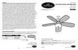
PACKAGE CONTENTS
A
B C D E F G
H I J K
Q R SP
O
N
M
L
PART DESCRIPTION QUANTITY
A Mounting Bracket 1
B Canopy 1
C Canopy Cover (preassembled to Canopy (B)) 1
D Yoke Cover 1
E Downrod 1
F Blade Bracket 5
G Blade Medallion 5
H Blade 5
I Motor Assembly 1
J Light Pan 1
K Light Kit 1
L Glass 1
M Finial (preassembled to Light Kit (K)) 1
N Bulb 3
O Light Frame 1
P Remote Control 1
Q Battery 1
R Adaptor Rubber Coupling 1
S Hanger Ball Rubber Coupling 1

4
Lowes.com/harborbreeze
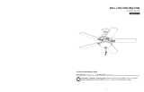
HARDWARE CONTENTS
Wire Connector
Qty. 4
Blade Screw
Qty. 15 + 1 extra
Motor Screw
(preassembled to
Motor Assembly (I))
Qty. 10 + 1 extra
Downrod Pin
(preassembled to
Downrod (E))
Qty. 1
Downrod Clip
(preassembled to
Downrod (E))
Qty. 1
Motor Housing Set
Screw
(preassembled to
Motor Assembly (I))
Qty. 2
Mounting Bracket Screw
(preassembled to
Mounting Bracket (A))
Qty. 4
Fitter Plate Screw
(peassembled to
Motor Assembly (I))
Qty. 3
II
Light Pan Bracket
Screw
(preassembled to
Light Pan (J))
Qty. 3
Rubber Washer
(preassembled to
Light Kit (K))
Qty. 1
Hex Nut
(preassembled to
Light Kit (K))
Qty. 1
Closemount Screw
(preassembled to
Motor Housing (I))
Qty. 3
AA
EE
JJ KK LL
FF
GG
HH
BB CC
DD

5
Lowes.com/harborbreeze
SAFETY INFORMATION
Please read and understand this entire manual before attempting to assemble, operate, or install the
product.
• Before you begin installing the fan, disconnect the power by removing fuses or turning off the circuit
breakers.
• Make sure that all electrical connections comply with local codes, ordinances, the National
ElectricalCode,andANSI/NFPA70-199.Hireaqualiedelectricianorconsultado-it-yourself
wiring handbook if you are unfamiliar with installing electrical wiring.
• Make sure the installation site you choose allows a minimum clearance of 7 ft. from the blades to
theoorandatleast30in.fromtheendofthebladestoanyobstruction.
• The net weight of this fan is: 23.3 lbs. (10.6 kg).
DANGER: When using an existing outlet box, make sure the outlet box is securely attached to
the building structure and can support the full weight of the fan. Failure to do this can result in serious
injury or death. The stability of the outlet box is essential in minimizing wobble and noise in the fan
after installation is complete.
WARNING: To avoid personal injury, the use of gloves may be necessary while handling fan
parts with sharp edges.
WARNING: Using a full-range dimmer switch to control fan speed will cause a loud humming
noisefromthefan.Toreducetheriskofreorelectricshock,doNOTuseafull-rangedimmerswitch
to control the fan speed.
WARNING: Toreducetheriskofre,electricshock,orpersonalinjury,mountthefantoanout-
let box marked “ACCEPTABLE FOR FAN SUPPORT” and use the mounting screws provided with the
outletbox.Mostoutletboxescommonlyusedforthesupportoflightingxturesarenotacceptablefor
fansupportandmayneedtobereplaced.Consultaqualiedelectricianifindoubt.Securetheoutlet
box directly to the building structure. The outlet box and its support must be able to support the mov-
ing weight of the fan (at least 35 lbs.). Do NOT use a plastic outlet box.
WARNING: Toreducetheriskofre,electricalshock,orpersonalinjury,wireconnectorspro-
vided with this fan are designed to accept only one 12-gauge house wire and two lead wires from the
fan. If your house wire is larger than 12 gauges or there is more than one house wire to connect to
the two fan lead wires, consult an electrician for the proper size wire connectors to use.
WARNING: Toreducetheriskofreorelectricshock,donotusethefanwithanysolid-state
speed-control device or control the fan speed with a full-range dimmer switch.
WARNING: Toreducetheriskofre,electricshock,orpersonalinjury,donotbendtheblade
arms when installing them, balancing the blades, or cleaning the fan. Do not insert objects between
the rotating fan blades.
WARNING: To reduce the risk of personal injury, use only parts provided with this fan. The use
of parts OTHER than those provided with this fan will void the warranty.

6
Lowes.com/harborbreeze
SAFETY INFORMATION
CAUTION: Read all instructions and safety information before installing your new fan. Review the
accompanying assembly diagrams.
CAUTION: Be sure the outlet box is properly grounded or that a ground (green or bare) wire is present.
CAUTION: Carefully check all screws, bolts, and nuts on the fan motor assembly to ensure that they
are secured.
PREPARATION
Before beginning the assembly of this product, ensure that all parts are present. Compare all parts
with the package contents list and hardware contents list. If any part is missing or damaged, do not
attempt to assemble the product.
After opening the top of the carton, remove the mounting hardware package from the foam inserts,
then remove the motor from the packaging and place it on a soft surface, such as a carpet, to avoid
damagetothenish.
Estimated Assembly Time: 120 minutes
Tools Required for Assembly (not included): Electrical Tape, Phillips Screwdriver, Pliers, Safety
Glasses, Step Ladder, and Wire Strippers
Helpful Tools (not included): AC Tester Light, Tape Measure, Wiring Handbook, and Wire Cutters

7
Lowes.com/harborbreeze
ASSEMBLY INSTRUCTIONS
1. Turn off the circuit breakers and the wall switch to the
fan supply line leads.
DANGER: Failure to disconnect the power
supply prior to installation may result in serious injury
or death.
1
2. Determine the mounting method to use.
Note: Flushmount installation is not available for this
item.
Important: If using the angle mount, check to ensure
the ceiling angle is not steeper than 20°.
2
3. Ensure that the blades (H) will be at least 30 in. from
any obstructions. Also check the downrod (E) length
to ensure the blades (H) will be at least 7 ft. above
theoor.
E
H
3
7' Min
30" Min

8
Lowes.com/harborbreeze
ASSEMBLY INSTRUCTIONS
4. Remove the motor screws (CC) from the underside
of the motor assembly (I).
Hardware Used
CC
Motor Screw x 10
4
I
CC
5. Install the mounting bracket (A) to the outlet box
by sliding the mounting bracket (A) over the two
mounting screws supplied by the outlet box. Securely
tighten the mounting screws.
Important: If using the angle mount, ensure that the
open end of the mounting bracket (A) is installed
facing the ceiling.
5
AA

9
Lowes.com/harborbreeze
STANDARD OR ANGLE MOUNTING INSTRUCTIONS
1. Remove the downrod pin (DD) and downrod clip
(EE) from the downrod (E). Then partially loosen the
motor housing set screws (FF) in the yoke at the top
of the motor assembly (I).
Hardware Used
DD
Downrod Pin x 1
EE
Downrod Clip x 1
FF
Motor Housing
Set Screw
x 2
I
E
EE
DD
FF
E
1
2. Insert the downrod (E) through the canopy (B),
canopy cover (C), and yoke cover (D). Thread
the wires from the motor housing assembly (I) up
through the downrod (E) and hanger ball rubber
coupling (S). This will prevent water from running
through the down rod.
E
S
B
C
D
I
2

10
Lowes.com/harborbreeze
STANDARD OR ANGLE MOUNTING INSTRUCTIONS
3. Slide the downrod (E) into the yoke of the motor
assembly (I), align the holes, and re-install the
downrod clip (EE) and downrod pin (DD). Then re-
tighten the motor housing set screws (FF) and slide
the yoke cover (D) down until it rests on top of the
motor assembly (I).
Hardware Used
DD
Downrod Pin x 1
EE
Downrod Clip x 1
FF
Motor Housing
Set Screw
x 2
DD
3
FF
E
EE
I
D
4. Install the hanger ball portion on the top of the
downrod (E) into the mounting bracket (A) opening.
Rotate the fan until the slot on the hanger ball
engages the tab on the mounting bracket (A).
WARNING: Be careful when aligning the tab
to the slot! If not fully engaged, there is a possibility
of the fan falling, which may result in serious injury or
death.
Proceed to the Wiring section of this manual.
A
A
E
4

11
Lowes.com/harborbreeze
CLOSEMOUNT INSTRUCTIONS
1. Remove the canopy cover (B) from the bottom of the
canopy (C).
Helpful Hint: Closemount-style mounting is more
suitable for ceilings lower than 8 ft. (2.44 m) high.
The downrod, hanging ball, and canopy cover are not
used in this type of installation.
1
C
B
2. Place the adaptor rubber coupling (R) over the yoke
of the motor assembly (I). Align the canopy (B) with
the holes in the top of the motor assembly (I). Secure
the canopy (B) to the top of the motor assembly (I)
with the closemount screws (LL).
Note: For outdoor installation, the closemount screws
(LL) are pre-installed at the factory.
Hardware Used
LL
Closemount Screw x 3
B
R
LL
I
2
3. Raise the fan and place the canopy (B) on the
mounting bracket (A) hook for wiring.
Proceed to the Wiring section of this manual.
B
A
3

12
Lowes.com/harborbreeze
WIRING
WARNING:Toreducetheriskofre,electricalshock,orpersonalinjury,wireconnectors
provided with this fan are designed to accept only one 12-gauge house wire and two lead wires from
the fan. If your house wire is larger than 12 gauges and there is more than one house wire to connect
to the two fan lead wires, consult an electrician for the proper size wire connectors to use.
WARNING: If the house wires are different colors than referred to in the following step, stop
immediately. A professional electrician is recommended to determine the correct wiring scheme.
CAUTION: Be sure the outlet box is properly grounded or that a Ground (Green or Bare) wire is present.
1. Connect the Black wire from the fan to the Black
wire from the ceiling. Connect the White wire from
the fan to the White wire from the ceiling. Connect
all Ground (Green) wires together from the fan to the
Bare/Green wire from the ceiling. Secure all wiring
connections together with wire connectors (AA).
Note: The Black wire is hot power for the fan. The White
wire is common for the fan and the light kit. The
Green wire is the grounded wire. If house wires
are different colors than referred to above, stop im-
mediately. It is recommended a professional elec-
trician determines the proper wiring.
Hardware Used
AA
Wire Connector x 4
1
Grounded/Green
Green/
Grounded
Outlet
Box
Supply Circuit
Receiv
er
Grounded/Green
White
white
black
White
Black
Black
black
white
green
2. Wrap electrical tape (not included) around each
individual wire connector (AA) down to the wire.
AA
AA
AA
2

13
Lowes.com/harborbreeze
WIRING
3. Turn the spliced/taped wires upward and gently push
the wires and wire connectors (AA) into the outlet
box.
WARNING: Ensure that no bare wire or wire
strands are visible after making connections. Place
the Green and White wire connections on opposite
sides of the outlet box from the Black and Blue (if
applicable) wire connections.
AA
3

14
Lowes.com/harborbreeze
FINAL INSTALLATION
1. Remove the two mounting bracket screws (GG) from
the mounting bracket (A) and loosen the other two
screws about 1/4 in. Then align the canopy (B) up to
the ceiling over the loose mounting bracket screws
(GG). Place the keyholes of the canopy (B) into the
screws (GG) and rotate clockwise.
Hardware Used
GG
Mounting Bracket
Screw
x 4
B
A
GG
1
2. Secure the canopy (B) with the previously removed
mounting bracket screws (GG) and securely tighten
all four screws (GG). Push the canopy cover (C) up
into the bottom of the canopy (B) until it is locked.
Note: Closemount installation will not have the downrod
(E) and canopy cover (C).
Hardware Used
GG
Mounting Bracket
Screw
x 4
B
C
GG
E
2
3. Place the blade bracket (F) onto the blade (H). Place
the blade medallion (G) into the three holes on the
opposite side of the blade (H). Secure the blade
bracket (F) and blade medallion (G) to the blade (H)
using the blade screws (BB). Repeat this step for the
remaining blades (H).
Hardware Used
BB
Blade Screw x 15
F
H
BB
G
3

15
Lowes.com/harborbreeze
FINAL INSTALLATION
4. Fasten the blade assembly to the motor assembly (I)
using two motor screws (CC) and tighten securely.
Repeat this step for the remaining blade assemblies.
Hardware Used
CC
Motor Screw x 10
CC
I
F
4
5. Removeoneofthethreetterplatescrews(HH)
fromthetterplateportionofthemotorassembly(I)
and save. Loosen but do not remove the other two
tterplatescrews(HH).
Hardware Used
HH
Fitter Plate
Screw
x 3
HH
I
5
6. Align the two key slots in the light pan (J) with the
loosenedtterplatescrews(HH)fromtheprevious
step. Place the light pan (J) over the two screws and
turn the light pan (J) clockwise until it locks. Then
tightenthetwotterplatescrews(HH).Re-install
thetterplatescrew(HH)thatwasremovedinthe
previousstepandtightenrmly.
Hardware Used
HH
Fitter Plate
Screw
x 3
J
HH
6

16
Lowes.com/harborbreeze
FINAL INSTALLATION
7. Remove one light pan bracket screw (II) from one of
the three brackets below the light pan (J) and save.
Loosen but do not remove the other two screws on
the other two brackets.
Hardware Used
II
Light Pan Bracket
Screw
II
x 3
J
II
7
8. Connect the blue wire from the motor assembly (I) to
the black wire from the light kit (K) and connect the
white wire from the motor assembly (I) to the white
wire from the light kit (K) by connecting the plugs.
8
I
K
9. Align the two key slots in the light kit (K) with the two
previously loosened light pan bracket screws (II).
Place the light kit (K) over the two screws and turn
the light kit (K) clockwise until it locks, then tighten
the two light pan bracket screws. Re-install the
previously removed light pan bracket screw (II) and
tightenrmly.
Hardware Used
II
Light Pan Bracket
Screw
II
x 3
K
II
9

17
Lowes.com/harborbreeze
FINAL INSTALLATION
10. Remove the rubber washer (JJ), hex nut (KK), and
nial(M)fromthelightkit(K)andsave.
Hardware Used
JJ
Rubber Washer x 1
KK
Hex Nut x 1
K
JJ
KK
M
10
11. Install the bulbs (N) into the sockets on the light kit (K).
Note: This fan has an energy-saving wattage limiter
included in the receiver. If you replace the included
40-watt candelabra-base bulbs with over 190 watts,
the fan will automatically turn off. Please ensure the
total bulb wattage is always below 190 watts.
K
N
11
12. Raise the glass (L) up against the light kit (K) and
secure it with the rubber washer (JJ), hex nut (KK),
andnial(M).
Hardware Used
JJ
Rubber Washer x 1
KK
Hex Nut x 1
12
K
L
JJ
KK
M

18
Lowes.com/harborbreeze
FINAL INSTALLATION
13. Align the three indents on the inside of the light frame
(O) with the three raised dimples on the light kit (K).
Turn the light frame (O) clockwise to hold the light
frame on the light kit (K).
O
K
13

19
Lowes.com/harborbreeze
OPERATING INSTRUCTIONS
1. Use the fan reverse switch, located on the top of the
motor assembly (I), to optimize your fan for seasonal
performance.
A ceiling fan will allow you to raise your thermostat
setting in the summer and lower your thermostat
setting in the winter without feeling a difference in
your comfort.
Note: Wait for the fan to stop before moving the
reverse switch.
1A. In warmer weather, push the reverse switch to the left
to display a Sun icon, which will result in downward
airowcreatingawindchilleffect.
1B. In cooler weather, push the reverse switch to the
righttodisplayaSnowakeicon,whichwillresultin
upwardairowthatcanhelpmovestagnant,hotair
off the ceiling area.
Important: The reverse switch must be set either
completely to the right or to the left in or-
der for the fan to function correctly. If the
reverse switch is set in the middle posi-
tion, the fan will not operate. See Fig. 1C.
Fig. 1A Fig. 1B
Fig. 1C
1
I
Note: The receiver is already wired and built into the housing of the fan at the factory. You do not
need to assemble the receiver.
2. Installing the Battery:
Remove the battery cover from the remote control
(P) and install the 12 V battery (Q). Ensure the plug
is fully attached to the battery (Q) and replace the
battery cover.
2
P Q
+
-

20
Lowes.com/harborbreeze
OPERATING INSTRUCTIONS
3. Control the fan and lights.
0 Low Speed
00 Medium Speed
000 High Speed
Turns the fan off
Turns the fan on
Press this button quickly
to turn the lights on or off.
To dim the lights, press
and hold this button.
Release the button when
the light is at the desired
level.
The receiver stores the
light setting when the light
is turned off. When the
light is turned on again,
it starts with the most
recent setting.
3
00
0
000
4. Your remote is pre-programmed at the factory and
will function correctly out of the box. However,
if it does need to be re-paired to the fan, do the
following: Within 30 seconds after turning the fan on,
press and hold the 0 and Light button in the center
of the remote control (P) at the same time for 5
seconds. The fan light will blink when the pairing is
complete.
4
00
0
000
P
/