Product names listed herein are trademarks of American Standard Inc.
American Standard Inc. 1999
C
Turn off hot and cold water
supplies before beginning.
CAUTION
SERVICE
4
CARTRIDGE
SCREEN
SPRING
CLIP
STOP
WASHER
TEST INSTALLED FAUCET
3
Turn HANDLES into OFF position.
Turn on water supplies, open stops and check all connections
for leaks.
Operate HANDLE to flush water lines thoroughly.
Turn handles OFF.
To change direction of handle rotation,
proceed as follows:
Turn valve to OFF position.
Remove INSERT and HANDLE SCREW.
Slip HANDLE with ADAPTER off.
Remove SPRING CLIP.
Lift STOP WASHER, turn 90° and replace.
Replace SPRING CLIP.
Replace ADAPTER, HANDLE, SCREW, and INSERT.
If spout drips, operate handles several times from
OFF to ON position. Do not force - handles turn only 90°.
To access CARTRIDGE:
Plastic SCREEN in CARTRIDGE may accumulate
dirt causing reduced water flow. To clean, first
turn off hot and cold water supplies, then:
Remove INSERT and HANDLE SCREW.
Slip HANDLE with ADAPTER off.
Unscrew CARTRIDGE with wrench.
Thoroughly rinse plastic SCREEN at
base of CARTRIDGE.
Replace CARTRIDGE until flange is
tight against valve body.
Turn valves OFF.
Replace ADAPTER, HANDLE, SCREW,
and INSERT.
1
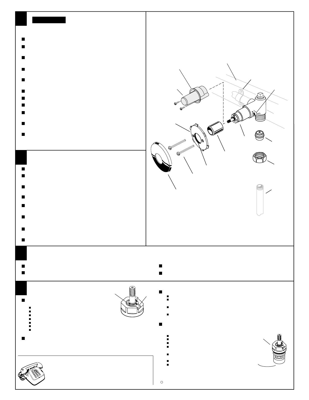
ROUGHING-IN FITTING
FINISHING INSTALLATION
2
Prepare water supplies per "Roughing-in Dimensions."
Slip COUPLING NUT over supply pipe and screw UNION SWIVEL
to pipe.
For Sweat Connection: Slip COUPLING NUT over 5/8'' O.D.supply
tube and solder tube into UNION SWIVEL or female inlet of stop.
Install VALVE at indicated height and depth. Note MAX WALL
marking on PLASTER GUARD for the finished wall.
Connect HOT water supply to left VALVE inlet and COLD water
supply to right VALVE inlet. Tighten both COUPLING NUTS firmly.
Secure VALVE BODY to cross brass of wall structure.
Cap roughing-in nipples, open supply lines and check for leaks.
Remove PLASTER GUARD. (Do not discard.) Open valves,
and check for leaks.
Close both valves, turn off water supplies, and replace
PLASTER GUARDS.
Remove roughing-in nipples.
Remove SCREWS holding PLASTER GUARDS and remove
PLASTER GUARD.
Slip VALVE COVER over VALVE CARTRIDGE. Push VALVE
COVER to complete stop.
Place FIXATION PLATE over VALVE ASSEMBLY. Line up
holes in FIXATION PLATE with THREADED TABS on VALVE.
Pass MOUNTING SCREWS (2) through FIXATION PLATE and
engage THREADED TABS. Tighten SCREWS securely.
Place ESCUTCHEON over FIXATION PLATE and push evenly
for a snap fit.
Assemble handle per separate "Handle Installation Instructions."
Remove HANDLE and adapter.
Use thin blade screwdriver to remove
ESCUTCHEON from FIXATION PLATE.
Unscrew MOUNTING SCREWS and
pull FIXATION PLATE from wall.
Pull off VALVE COVER.
34803N
"MAX WALL"
THREADED
TABS
CROSS
BRACE
M
A
X
W
A
L
L
PLASTER
GUARD
UNION
SWIVEL
COUPLING
NUT
VALVE
MOUNTING
SCREWS
O-RING
FIXATION
PLATE
VALVE
COVER
SUPPLY
PIPE
PIPE
STRAP
ESCUTCHEON
VALVE
CARTRIDGE
Add cross braces to wall structure and secure piping.
Finish wall construction. NOTE: Apply wall finish as close as
possible to the PLASTER GUARD.
Place O-RING in FIXATION PLATE as shown.
HOTLINE FOR HELP
For toll-free information and answers to your questions, call:
1 (800) 442-1902
Weekdays 8:00 a.m. to 7:00 p.m. Eastern Time
Saturdays 8:00 a.m. to 4:00 p.m. Eastern Time
IN CANADA 1-800-387-0369 (TORONTO 1-416-536-5609)


