Commercial Electric MS8332C Operating instructions

Category
Measuring, testing & control
Type
Operating instructions

This manual is also suitable for

MS8332C
730 696
Indicates important safety information
3
Equipment protected throughout by double insulation or reinforced
insulation.
(MEASUREMENT CATEGORY III) is applicable to test and measuring
circuits connected to the distribution part of the buildings low-voltage
MAINS installation.
Fuse
AC (Alternating Current)
DC (Direct Current)
AC or DC (alternating current or direct current)
Diode
Continuity buzzer
Auto range
There is not enough battery power for sufficient operation
2
This digital multimeter is designed and manufactured according to safety requirements
of EN 61010-1:2010, EN 61010-2-030, EN 61010-2-033, EN 61010-031 on electronic
measuring instrument and hand-helddigital multipurpose meter. This meter conforms
to UL STD.61010-1,61010-2-030,61010-2-033, Certified to CSA STD.C22.2 NO.61010-1,
61010-2-030, IEC STD61010-2-033. The product meets with the requirements of 600V
CAT III and pollution degree 2.
The meter can be used for measuring DC voltage, AC voltage, resistance, diode,
buzzer, cont
inuity test, DC current, and AC current. The unique non-contact AC voltage
detection feature of this multimeter and the full scale AC 220V protection design allows
for safe operation.
This series of meters can be widely used for schools, labs, research institutes,
enterprises, and factories. Please read this manual carefully and pay attention to
related safe working standards before using this meter. Protection provided by the
instrument will be impaired if used in a manner not specified by the manufacturer.
PRELIMINARY PRECAUTIONS
SYMBOLS
2
2
6
7
11
18
18
19
19
6
FCC Compliance Statement
WAR NING: When u sing the meter, the user
must observe all no rmal safety rules
concerning the pr otection against the
dangers of electr ical current and
protection of the m eter against misuse.
WAR NING: When t he meter is delivered,
check that it has not b een damaged in
transit.
Conforms to UL STD. 61010-1, 61010-2-030 and 61010-031
WARNING: BE EXTREMELY CAREFUL IN THE USE OF THIS METER. Improper
use of this device can result in electric shock or destroy the meter. Follow
all safeguards suggested in this manual and the normal safety precautions
used in working with electrical circuits. Do not service this device if you are
not qualified to do so. To ensure safe operation, and in order to exploit to
the full the functionality of the meter, please follow the directions in this
section carefully.
76
Warranty
For one year from the date of purchase, this product is warranted against any defects
in material or workmanship. This warranty is void if this product is ever used while
providing commercial services or if rented to another person. Contact the Customer
Service Team at 1-877-527-0313 or visit www.homedepot.com.
WARRANTY: 12 months
PACKAGE CONTENTS
Pre-Operation
Part Name
Quantity
A
B
Multimeter
Black test lead
C
Red test lead
Non-contact AC Voltage
Indicator Light
LCD Display
Alerts you to live voltages to ensure safe
operation of this meter.
Displays the measurement result.
D
E
1
1
1
A
I
B
D
E
F
G
H
C
FCC Compliance
S
tatement
Presst hek eyt oh oldt hed ata presst he
key2s econdst oo pent heb acklight
Hold/Backlight Key
F
Part Name
Description
PRODUCT DESCRIPTION
98
Pre-Operation (continued)
PRODUCT SPECIFICATIONS
Pre-Operation (continued)
Component Specication
Automatic Measuring Range
DMM, full range is 3999 counting
Overload Protection
Full range protection
Altitude
Up to 2000 meters
Battery
2x1 5V AAA batteries
Auto power-off time
30 minutes
Data
Hold function
Safety Class
EN61010-1, CAT III 600V
Over range indication
LCD displays “OL
Ambient Temperature
25°C Relative Humidity: <75%
Operating environment
0°C - 40°C (3F - 104°F), <80% relative
humidity and 1C non-condensing
Storage temperature
- 10°C - 50°C (14°F - 12F), <70% relative
humidity, battery removed
Size
Weight
116 x 61 x 38 5 mm
Approx.
.
Approx.
.
190 g
DC VOLTAGE SPECIFICATIONS
Measuring Range Resolution
400mV
Accuracy
0.1mV
4V 1mV
40V 10mV
400V 100mV
±(0.5% of rdg + 3 digits)
600V
1V
±(0.8% of rdg + 5 digits)
Additional specifications:
I nput Impedance: 10MΩ
M aximum Input Voltage: 600V DC
AC VOLTAGE SPECIFICATIONS
Used to select functions and desired ranges.
Select Switch
Switching key between frequency and duty
cycle, it is used for switching Hz and % at
voltage range and current range.
Hz% Switching Key
H
I
Measuring Range Resolution Accuracy
4V 1mV
40V 10mV
400V 100mV
±(0.8% of rdg + 3 digits)
600V
1V
±(1.0% of rdg + 5 digits)
Additional specifications:
I nput Impedance: 10MΩ
F requency Range: 40 - 400Hz
R esponse: Average response (calibrated in rms of sine wave)
M aximum Input Voltage: 600V rms AC
DC CURRENT SPECIFICATIONS
Measuring Range Resolution Accuracy
400uA 0.1uA
4000uA
40mA
±(1.8%o fr dg + 5 digits)
400mA
1uA
10uA
100uA
Additional Specifications:
M ax. Current: 400mA
O verload Protection: mA measuring range: FF400mA/600V fuse
AC CURRENT SPECIFICATIONS
Measuring Range Resolution Accuracy
400uA 0.1uA
4000uA
40mA
±(2 0%o fr dg + 8 digits)
400mA
1uA
10uA
100uA
The voltage current range is used for
switching AC/DC mode, the resistance range
is used for switching mode.
Function Selection Key
G
CAP
400nF 0.1nF
±(5.0% ofr dg + 15 digits)
4uF
40uF
100uF
1nF
10nF
100nF
±(5.0% ofr dg + 25 digits)
Additional Specifications
O verload Protection: 250V DC or rms AC
FREQUENCY SPECIFICATIONS
Measuring Range Accuracy
1Hz – 5MHz
±(1.5% ofr dg + 15 digits)
DUTY CYCLE
Measuring Range Accuracy
0.5-99.9%
±(2.0% ofr dg + 5 digits)
BATTERY T EST
Measuring Range Accuracy
1.5V
±(2.0% ofr dg + 20 digits)
9V
BEFORE YOU TAKE A MEASUREMENT
Operation
1110
Pre-Operation (continued)
Additional Specifications:
M ax. Current: 400mA
O verload Protection: mA measuring range: FF400mA/600V fuse
Additional Specifications:
O pen Circuit Voltage: Diode is approximately 1.5V, buzzer is approximately
0 .5V
O verload Protection: 250V DC or rms AC
CAPACITANCE SPECIFICATIONS
Pre-Operation (continued)
Measuring Range Resolution Accuracy
4nF
0.001nF
40nF
0.01nF
±(5.0%o fr dg + 0.6 digits)
±(5.0%o fr dg + 30 digits)
F requency Range: 40Hz – 400Hz
R esponse: Average, calibrated in rms of sine wave
RESISTANCE SPECIFICATIONS
Measuring Range Resolution Accuracy
400Ω
±(1 0%o fr dg + 3 digits)
4kΩ
40kΩ
400kΩ
4MΩ
40MΩ
1KΩ
10KΩ
100Ω
10Ω
1Ω
0 1Ω
±(1 2%o fr dg + 15 digits)
Additional Specifications:
M aximum Open Circuit Voltage: 0.25V
O verload Protection: 250V DC or rms AC
DIODE AND CONTINUITY SPECIFICATIONS
Measuring Range Function
Display shows approximate forward voltage of diode.
Built-in buzzer sounds if resistance is lower than 50±20Ω.
1514
Operation (continued)
Measuring diode
Operation (continued)
3
CAUTION: To avoi d the meter or measured
equipment from be ing damaged, cut off all
power supply of mea sured circuits and
discharge all hig h voltage capacitors
before measurin g diode.
T urn the rotary switch to the
p osition (1).
P ress the FUNC key (2) and select the
m easuring range.
S eparately connect the black and read
t est leads to the negative pole and
p ositive pole of the measured diode.
T he meter displays the forward bias value
o f the measured diode. If the poles of the
t est leads are connected inversely, the
m eter will display “OL.
For on-line measuring diode, the
meter displays the forward voltage
drop at forward measurement; the
reversem easurement depends on
the values of other elements
connected in parallel at both ends
of diode.
Measuring continuity
4
CAUTION: To avoi d the meter or measured
equipment from be ing damaged, cut off all
power supply of mea sured circuits and
discharge all hig h voltage capacitors be fore
continuity meas urement.
Turn the rotary switch to the
p osition (1).
P ress the FUNC key (2) and select the
m easuring range.
S eparately connect the two ends of the
t est leads to the end ends of the
m easuredp art and circuit.
The meter displays the approximate
r esistance value between measured
p oints. Here if the resistance value
b etween measured points is less than
5 0±20 Ω, the b
uzzer will make a sound.
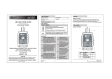
Measuring AC and DC current
7
WAR NING: To avoid damage to t he meter or
injury if the fuse bl ows, never attempt an
in-circuit curr ent measurement where t he
open-circuit po tential to earth (groun d) is
greater than 250V.
The DC current range is 400uA, 4.000mA,
40.00mA, and 400.0mA .The AC current
range is 400uA, 4.000mA, 40.00mA,
and 400.0mA.
NOTE: Connect the m easuring current of
the meter in series , not connected in
parallel. This pr events damage to the
meter or endanger ing personal safety.
C ut off the power of the measured circuit.
D ischarge all high voltage capacitance on
t he measured circuit.
Turn the rotary switch to the mA or uA
p osition (1). When the measured current
i s less than 400uA, select the uA position.
W hen the measured current is
4 mA~400mA, select the mA position.
D isconnect the circuit under test. Connect
t he black test lead to the end of dis
c onnected circuit under test (with lower
v oltage). Connect the red test lead to the
o ther end of the disconnected circuit
u nder test (with higher voltage).
S witch on the power of t
he circuit, and then
r ead the reading displayed on the LCD. If the
d isplay only displays “OL, it indicates that
t he input exceeds the selected range. Move
t he rotary dial to a higher range.
C ut off the power to the measured circuit.
D ischarge all capacitances, take off the
t est leads and recover the circuit.
When measuring DC c urrent, if the test
leads are reverse ly connected to the
circuit , the displ ay will change into
negative, but not a ffect measuring
accuracy.
1716
Operation (continued)
Measuring capacitance
Operation (continued)
5
CAUTION: To avoi d the meter or measured
equipment from be ing damaged, cut off all
power supply of mea sured circuits and
discharge all hig h voltage capacitors be fore
on/off measurem ent.
The capacitance ranges of the meter are
4.000nF, 40.00nF, 400.0nF, 4.000uF,
40.00uF, 100.0uF.
Turn the rotary switch to the
p osition (1).
P ress the FUNC key (2) and select the
C AP measuring range.
Apply the two ends of the test leads to
m easure the two pins of the capacitance
u nder test and read the measured value
o n the LCD.
NOTE: The meter wil l take some time to
stabilize the rea ding when the capacitan ce
is high. A small capa citance with less than
10nF subtracts fr om the distribution
capacitance of th e meter and lead ( namely
displayed base nu mber) when measuring.
Measuring frequency and duty cycle
6
Turn the rotary switch to the
p osition (1).
P ress the Hz% key (2). For frequency,
s elect the Hz range. For duty cycle,
s elect the % range.
Apply the two ends of the test leads to
m easure the frequency or duty cycle
v alue of the circuit under test.
R ead the value that displays on the LCD.
  • Page 1 1
  • Page 2 2
  • Page 3 3
  • Page 4 4
  • Page 5 5
  • Page 6 6
  • Page 7 7
  • Page 8 8
  • Page 9 9
  • Page 10 10

Commercial Electric MS8332C Operating instructions

Category
Measuring, testing & control
Type
Operating instructions
This manual is also suitable for

Ask a question and I''ll find the answer in the document

Finding information in a document is now easier with AI