1 Startup Manual
STARTUP MANUAL
PCI-1730U
32-channel Isolated Digital I/O Card
Before installation, please make sure that you have
received the following:
• PCI-1730U card
• Driver CD
• Quick Start User Manual
If anything is missing or damaged, contact your
distributor or sales representative immediately.
For more detailed information on this product,
please refer to the PCI-1730U_1733_1734 User
Manual on the CD-ROM (PDF format).
CD:\Documents\Hardware Manuals\PCI.
FCC Class A
This equipment has been tested and found to comply with
the limits for a Class A digital device, pursuant to part 15 of
the FCC Rules. These limits are designed to provide reason-
able protection against harmful interference when the
equipment is operated in a commercial environment. This
equipment generates, uses, and can radiate radio frequency
energy and, if not installed and used in accordance with the
instruction manual, may cause harmful interference to radio
communications. Operation of this equipment in a residen-
tial area is likely to cause interference in which case the
user is required to correct interference at his own expense.
CE
This product has passed the CE test for environmental spec-
ifications when shielded cables are used for external wiring.
We recommend the use of shielded cables. This kind of
cable is available from Advantech. Please contact your local
supplier for ordering information.
The Advantech PCI-1730U is a 32-channel isolated
digital input/output card for the PCI bus. For easy
monitoring, each isolated digital input channel is
equipped with one red LED, and each isolated digi-
tal output channel is equipped with one green LED
to show its ON/OFF status. The PCI-1730U’s iso-
lated digital input channels are ideal for digital input
in noisy environments or with floating potentials.
The PCI-1730U provides specific functions for dif-
ferent user requirements.
Isolated Digital Input
Isolated Digital Output
Non-isolated Digital Input/Output
General
Packing List Specifications
User Manual
Declaration of Conformity
Overview
Notes
For more information on this and other Advantech
products, please visit our websites at:
http://www.advantech.com/eAutomation
For technical support and service:
http://www.advantech.com/support/
This startup manual is for PCI-1730U.
Part No.2003173020 1st Edition
April 2009
Number of Channel
16(bi-directional)
Optical Isolation 2,500 V
DC
Opto-isolator response
time
25 µs
Over-voltage Protect 70 V
DC
Input Voltage
VIH (max.) 30 V
DC
VIH (min.) 5 VDC
VIL (max.) 2 VDC
Input Current
5 V
DC 1.4 mA (typical)
12 V
DC 3.9 mA (typical)
24 V
DC 8.2 mA (typical)
30 V
DC 10.3 mA (typical)
Number of Channel 16
Optical Isolation 2,500 V
DC
Output Voltage Open collector 5 to 40 VDC
Sink/Source Current 200 mA max./channel
Input Channels 16
Input Voltage
Low 0.8 V max.
High 2.0V min.
Output Channels 16
Output Voltage
Low 0.5 V max. @ + 24 mA (sink)
High 2.4V min. @ - 15 mA (source)
I/O Connector
Type
37-pin D-Sub female
Dimensions 175 mm x 100 mm ( 6.9" x 3.9" )
Power
Consumption
Typical
+5 V @ 250 mA
+12 V @ 35 mA
Max.
+5 V @ 400A
+12 V @ 60mA
Temperature
Operation
0 ~ +60°C ( 32~ 140°F )
(refer to IEC 68 -2 - 1 ,2)
Storage -20 ~ +85°C ( -4 ~185°F )
Relative Humidity
5 ~ 95% RH non-condensing
( refer to IEC 68-2-3)
Certification CE certified
4 Startup Manual
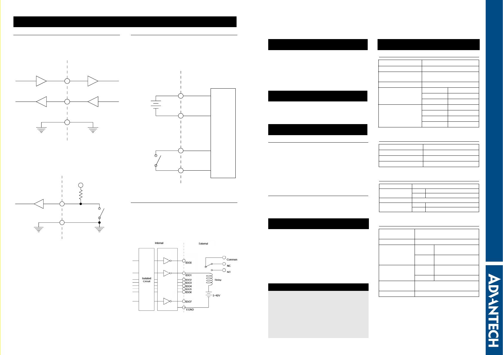
TTL-level Digital Input/Output
The PCI-1730U has 16 TTL-level digital inputs and 16
TTL-level digital outputs. The following figure shows
connections to exchange digital signals with other TTL
devices:
If you want to receive an OPEN/SHORT signal from a
switch or relay, add a pull-up resistor to ensure that the
input is held at a high level when the contacts are open.
See the figure below:
Isolated Digital Input
Each of the 16 isolated digital input channels accept
voltages from 5 to 30 V. Every eight input channels
share one external common. (Channels 0 ~ 7 use
ECOM0. Channels 8 ~ 15 use ECOM1.) The follow-
ing figure shows how to connect an external input
source to the card's isolated inputs.
Isolated Digital Output
PCI-1730U provides 16 isolated DO channels. If the
external voltage (5 ~ 40V) is connected to each isolated
output channel (IDO) and its isolated digital output
turns on (300 mA per channel maximum), the card's
current will sink from the external voltage.
CN5 provides two EGND pins for IDO connection.
Connections
DO
DI
GND
PCI-1730 TTL device
U
DI
GND
Switch
+5V
4.7K
PCI-1730
U
ECOM
EGND
Isolated
Circuit
Internal
Wet
contact
Dry
Contact
IDI0
IDI1
External


