Omega USB-4750 User manual
- Category
- Digital & analog I/O modules
- Type
- User manual
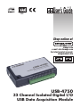
Omega USB-4750 is a powerful data acquisition (DAS) module for the USB port. It features a unique circuit design and complete functions for data acquisition and control. USB-4750 has 32 isolated digital input/output channels and supports high-voltage isolation up to 2,500 VDC on all channels. It also supports dry/wet contact for digital input, interrupt handling capability, high-sink current for isolated output channels (100mA max./Channel), and digital output value retained after hot system reset.
Omega USB-4750 is a powerful data acquisition (DAS) module for the USB port. It features a unique circuit design and complete functions for data acquisition and control. USB-4750 has 32 isolated digital input/output channels and supports high-voltage isolation up to 2,500 VDC on all channels. It also supports dry/wet contact for digital input, interrupt handling capability, high-sink current for isolated output channels (100mA max./Channel), and digital output value retained after hot system reset.


-
 1
1
-
 2
2
-
 3
3
-
 4
4
-
 5
5
-
 6
6
-
 7
7
-
 8
8
-
 9
9
-
 10
10
-
 11
11
-
 12
12
-
 13
13
-
 14
14
-
 15
15
-
 16
16
-
 17
17
-
 18
18
-
 19
19
-
 20
20
-
 21
21
-
 22
22
-
 23
23
-
 24
24
-
 25
25


Omega USB-4750 User manual
- Category
- Digital & analog I/O modules
- Type
- User manual
Omega USB-4750 is a powerful data acquisition (DAS) module for the USB port. It features a unique circuit design and complete functions for data acquisition and control. USB-4750 has 32 isolated digital input/output channels and supports high-voltage isolation up to 2,500 VDC on all channels. It also supports dry/wet contact for digital input, interrupt handling capability, high-sink current for isolated output channels (100mA max./Channel), and digital output value retained after hot system reset.
Ask a question and I''ll find the answer in the document
Finding information in a document is now easier with AI
Related papers
-
Omega TXUN-KIT Owner's manual
-
-
-
-
-
-
Omega USB-4751/USB-4751L Owner's manual
-
-
-
Other documents
-
Toshiba AD368 User manual
-
Advantech USB-4750 User manual
-
Omega Engineering OM-DAQ-USB-2401 User manual
-
Advantech PCI-1730U User manual
-
Bahco Tool Holders Collection User manual
-
 Distek 2500 Select Operating instructions
-
GE Druck DPI 821 User manual
-
-
-
Koolmore CS312-16S Installation guide
