Page is loading ...

Hytork
Dossier
Twin Port
Actuators (0-90˚)
& QA Series
Contents
Important Safety Procedures
Repair Kits
Complete Disassembly
Assembly Instructions
Piping Instructions
Testing the HYTORK Actuator
Testing and Cycling of
Infrequently Used or
Stored Actuators
Service
1 Important Safety
Procedures
Qualified maintenance personnel
should read and follow these
straightforward instructions.
ALWAYS disconnect the Air and Electrical
supplies before carrying out any form of
maintenance on an Actuator.
Caution: When removing any ball valve
or plug valve assemblies from a pipe
system, isolate the piping system on
which the Actuator is installed and relieve
any media pressure that may be trapped
in the valve cavities before removing the
Actuator for maintenance.
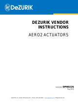
Caution: When working with Spring
Return Actuators, always contain the
Spring tension with HYTORK Retractor
Rods as shown in Fig. 2 (Spring Return
End Cap Assembly). Follow instructions
for using the Retractor Rod carefully.
Only HYTORK manufactured or approved
Retractor Rods are to be used for Spring
removal. As with any threaded tool that
is frequently used, Retractor Rods should
be checked to ensure that the threads
are not worn or damaged in any way
and greased regularly. Any damaged
or worn rod must not be used and
must be destroyed.
Caution: Never attempt to ‘BLOW OUT’
the Pistons from the Actuator Body by
using air pressure when the End Caps
have been removed.
Read the relevant sections
carefully before continuing.
2 Repair Kits
Recommendations.
HYTORK provide parts for their range
of Actuators in kit form and it is
recommended that when replacing
‘0’ Rings, that ALL ‘O’ Rings are replaced
while the Actuator is disassembled.
Spares Kits.
Each HYTORK Actuator Repair Kit
includes the following items:
Infix Coils 2
Infix Coil Hole Plugs 2
Top Pinion Washer 1
Top Pinion Snap Ring 1
Top Pinion ‘O’ Ring 1
Bottom Pinion ‘O’ Ring 1
Piston ‘O’ Ring 2
End Cap ‘O’ Ring 4
Retractor Rods.
HYTORK Retractor Rod Sets are available
from HYTORK or your local Stocking
Distributor of HYTORK products.
3 Complete
Disassembly
Double Acting
Models
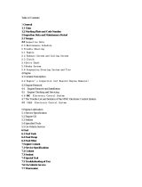
Removal of Travel Stops (if supplied).
Unscrew and remove both Travel Stops,
which are located at the base of the
Actuator body centre section on the side
opposite to the Actuator air connections
(see Fig. 1).
Removal of End Caps.
Unscrew the two seal plugs that are
located in the body next to each end cap,
to permit the infix coil to exit. Rotate the
end cap in the direction that causes the
infix coil to come out of the hole. The
rotation should continue about one full turn
at which point the coil can be pulled from
Installation,
Operating and
Maintenance
Instructions
Installation, Operating and Maintenance Instructions Twin Port Actuators (0-90˚) & QA Series
MAC129916
1
MAC129916
1
2
3
4
5
6
7
8
Quality
Assured
registered
management
systems
to ISO 9001

the hole. Having removed the coil from
one end cap, repeat the operation with the
other end cap. When both coils have been
removed, push out the end caps part way
by rotating the pinion. Remove the end
caps by pulling them free from the body,
avoiding any ‘cocking’ of the end caps.
Removal of Pistons.
Rotate the pinion by means of a wrench
to drive the pistons apart until the pinion
rotates freely. Rotate the pistons in the
cylinder bore approximately 10 degrees.
Rotate the pinion carefully and the pistons
will push free of the cylinder bore.
Removal of Pinion.
Remove the snap ring and washer from
the top of the pinion and CAREFULLY push
the pinion from the cylinder body. Care
MUST be taken to ensure that the pinion
does not damage the bores during this
operation. If necessary remove any burrs
etc. before removing the pinion.
Inspection.
Clean and examine all parts
for damage and wear.
Spring Return
Models
Removal of End Caps.
Place the HYTORK RETRACTOR ROD
through the hole in the end caps and
screw the rod into the spring retractor
plate until it is fully engaged. Thread
engagement should be at least 1/2"
(12mm) and the rod should be tightened
by using locknuts to ensure complete
engagement.
Unscrew the two seal plugs that are
located in the Actuator body next to each
end cap, to permit the infix coil to exit.
Screw the nut and washer closest to the
end cap clockwise down the RETRACTOR
ROD until they come up against the end
cap. Using a wrench, continue to screw
the nut clockwise down the rod AT LEAST
two complete turns to draw the spring
retractor plate away from the piston head
(see Fig. 2).
Rotate the end cap in the direction which
causes the infix coil to come out of the
hole. The rotation should continue about
one full turn at which point the coil can
be pulled from the hole. Having removed
the coil from one end cap, repeat this
operation with the other end cap. When
both coils have been removed, push out
the end caps part way by rotating the
pinion. Remove the end caps by pulling
them free of the body, avoiding any
‘cocking’ of the end caps.
Dismantling of the
Body Sub-Assembly.
These operations are as described for
Double Acting Actuators, for Removal of
Pistons, Removal of Pinion and Inspection.
2
Fig. 2Spring Return End Cap Assembly
Retractor plate
‘O’ Rings Infix coil
Springs
Washer
Retractor rod
Nut
Locknuts
Actuator body
Piston
Infix coil seal plug End cap
Fig. 1Travel Stop Assembly
Piston
Body
Opening Stop
Closing Stop
Externally adjustable
travel stops (one for
each end of travel)
End Cap
AB
BA
Pinion
Section ‘B-B’
Section ‘A-A’

3
4 Assembly
Instructions
Double Acting
Models
Inspection.
Check that all components are clean
and free from damage.
Fitting the Pinion.
Fit ‘O’ Rings to the pinion and grease the
pinion all over using a MOLYBDENUM
based grease. Push the pinion into the
cylinder body, taking CARE not to damage
the bores with the pinion gear. Slight
rotation of the pinion will assist when
trying to enter the ‘0’ Rings. Fit the pinion
washer and the snap ring.
Rotate the Pinion so that when viewed
from the top of the body (as shown in
Fig. 3a), the Pinion flat faces are at
approximately 30˚. If Travel Stops are
fitted, the grub screw hole on the top of
the pinion must be facing away from the
air inlet ports (as shown in Fig.3b). This
ensures that the machined Travel Stop
Flats on the base of the pinion are in the
correct position.
Fitting the Pistons.
Grease the pistons and Actuator cylinder
bore, using a MOLYBDENUM based
grease, fit the piston ‘O’ Rings. Insert the
pistons into the cylinder bore (one piston
in each end) with the gear teeth facing
each other (as shown in Fig. 4). When the
pinion is rotated clockwise as viewed from
the top of the body, the pistons are drawn
together. The top pinion drive flats should
be at RIGHT ANGLES to the axis of the
Actuator body.
Fitting the Travel Stops
(where supplied).
With the pistons together, screw in the
travel CLOSING stop until it comes into
contact with the pinion (Fig. 1). Rotate the
pinion to drive the pistons apart only 90
degrees and screw in the Travel OPENING
stop until it comes into contact with the
pinion (Fig. 1).
Hytork Actuators have an overtravel of
1.5 degrees at either end of the stroke,
and the Travel Stops permit adjustment
of 10 degrees including the overtravel (as
shown in Fig. 4). Final adjustment is easily
made when the Actuator has been re-fitted
to its valve, damper or other device, to
suit individual requirements.
Fitting the End Caps.
Grease the retaining coil grooves in the
cylinder bore and on the end cap. Fit the
two ‘O’ Rings in the grooves in the end cap
from which the originals were removed
and insert the cap into the Actuator body
so that the Drive Pin located in the wire
groove of the end cap is positioned
approximately 0.75” (19mm) radially
past the infix coil entry hole on the
Actuator body.
Insert the Infix Coil into the hole and then
rotate the end cap, keeping the infix coil
against the drive pin. Rotate the end cap
until the end of the infix coil is flush with
the Actuator body. Refit the two seal
plugs into the infix coil entry holes.
IMPORTANT: ALL HYTORK ACTUATOR
REPAIR KITS ARE SUPPLIED WITH
INFIX COILS CUT TO AN EXACT
LENGTH THAT WILL FIT THE FULL
CIRCUMFERENCE OF THE END CAP.
ANY SHORTENED COIL MUST NOT BE
USED. IF IN DOUBT CONTACT HYTORK
OR YOUR LOCAL DISTRIBUTOR.
Spring Return
Models
Assembly of Pinion,
Pistons and Limit Stops.
Assemble in accordance with the
instructions for Double Acting models.
Fitting the End Caps.
Using the HYTORK RETRACTOR ROD, pull
the springs into the end cap so that the
spring retractor plate will not touch the
piston head when the module is fully
inserted into the Actuator body.
Grease the retaining coil grooves in the
cylinder bore and on the end cap. Fit the
two ‘O’ Rings to the cap in the grooves
from which the originals were removed
and insert the cap in the body so that the
Fig. 3a
Pinion
position
after
Pistons
fitted
Air
inlet
ports
Body Top Pinion washer
Rotate Pinion to this
position (dotted lines)
Pinion
snap
ring
Actuator body viewed from
top showing Pinion postions
Fig. 4
Viewed from above
Gear teeth
Air inlet holes
Air
inlet
ports
Grub screw hole
Travel Stop flats
Travel
Stops
entry
hole
Fig. 3b
1.5˚
1.5˚
10˚
90˚
10˚
Opening
Stop
Closing
Stop

4
drive pin located in the coil groove is
positioned approximately 0.75” (19mm)
radially past the infix coil entry hole
on the body.
Insert the infix coil into the hole and then
rotate the cap keeping the infix coil
against the drive pin. Rotate the cap until
the end of the infix coil is flush with the
Actuator body. Refit the two seal plugs
in the infix coil entry holes.
IMPORTANT: ALL HYTORK ACTUATOR
REPAIR KITS ARE SUPPLIED WITH
INFIX COILS CUT TO AN EXACT
LENGTH THAT WILL FIT THE FULL
CIRCUMFERENCE OF THE END CAP.
ANY SHORTENED COIL MUST NOT BE
USED. IF IN DOUBT CONTACT HYTORK
OR YOUR LOCAL DISTRIBUTOR.
When the end cap is in place, remove
the HYTORK Retractor Rod completely,
by firstly releasing the nut and washer
against the Actuator end cap and then
unscrewing the rod by using the two
locked nuts at the end of the
Retractor Rod.
5 Piping
Instructions
See Fig. 5 for piping instructions.
6 Testing the
HYTORK Actuator
Using compressed air at 80-100 psi
(5.5 - 7 bar) check the seal areas with
soapy water, ensuring there are no leaks
and that the Pinion rotates smoothly over
its full travel.
7 Testing and
Cycling of
Infrequently Used
or Stored Actuators
Actuators not in current use (i.e. Actuators
in storage or stock and/or not operated
for at least a 3 month period), should be
cycled a minimum of ten times and tested
against the possible ‘pre-set’ of the seals.
This is a safety precaution recommended
by the Seal manufacturers.
8 Service
It is the policy of HYTORK to give the best
possible service to our customers. We are
happy to assist you in any way we can and
if you have any questions about HYTORK
Actuators or other HYTORK Products
please do not hesitate to contact one of
HYTORK'S VALVE AUTOMATION CENTERS
or your local HYTORK Stocking Distributor.
MAC129916
Quality
Assured
registered
management
systems
to ISO 9001
UK Patents:
GB 2 102 887 B;
GB 2 123 517 B;
GB 2 138 505 B;
GB 2 216 229 B;
GB 2 225 079 B;
GB 2 229 254 B;
GB 2 253 459 B;
GB 2 268 574 B.
US Patents:
4,496,071;
4,651,627;
4,716,815.
Warranties:
Unauthorised
modification to
any Hytork
Product totally
invalidates all
warranties.
Important:
We have endeavoured
in this publication to
make the contents as
accurate as possible,
but being given as
general information, it
is not to be taken as
binding unless
specifically confirmed
in writing. Due to
Hytork's continuing
commitment to
engineered product
advancement, the
product specifications
and data presented in
this publication are
subject to change
without notice.
Hytork Controls Inc.
Valve Automation Center Tel: [+1] (813) 630 2255
9009 King Palm Drive Fax: [+1] (813) 630 9449
Tampa, Florida 33619 Email: [email protected]
USA http://www.hytork.com
Hytork Controls Australian Operations
25 South Street Tel: [+61] (2) 9841 2414
Rydalmere Fax: [+61] (2) 9684 6439
NSW 2116 Email: [email protected]
Australia http://www.hytork.com
Hytork Controls Europe
Valve Automation Center
6 Bracken Hill
Southwest Industrial Estate Tel: [+44] (0191) 5180020
Peterlee Fax: [+44] (0191) 5180032
County Durham Email: [email protected]
SR8 2LS UK http://www.hytork.com
Hytork Controls Europe
Ryeford Road South
Kings Stanley Tel: [+44] (01453) 827710
Stonehouse Fax: [+44] (01453) 827714
Gloucestershire Email: [email protected]
GL10 3HG UK http://www.hytork.com
Part of the Hytork International plc Group
Fig. 5Piping instructions
Spring
Return
Actuator
Double
Acting
Actuator
/