Page is loading ...

104-10T
PARTS BOOK
AND INSTRUCTION MANUAL

INDEX
1. SPECIFICATIONS ..............................................................................2
2. DESCRIPTION ...................................................................................2
3. SPEED ................................................................................................2
4. TO OIL THE MACHINE ......................................................................3
5. NEEDLES, NIPPLE AND THREAD ...................................................4
6. TO REMOVE, REPLACE AND SET NEEDLE AND NIPPLE ............5
7. TO THREAD THE MACHINE .............................................................7
8. LEARNING TO OPERATE THE MACHINE .......................................10
9. TO OPERATE THE MACHINE ...........................................................10
10. TO REGULATE THE PRESSURE ON THE PRESSER FOOT ..........11
11. TENSIONS ..........................................................................................11
12. TO ADJUST THE LENGTH OF STITCH ............................................12
13. TO REGULATE THE PRESSURE ON THE NIPPLE .........................12
14. THE LOOPER .....................................................................................13
15. TO SET THE LOOPER .......................................................................14
16. TO ADJSUT THE NUMBER OF THE BRAIDING ..............................14
17. TO ADJUST THE TENSION OF THE BRAIDING ..............................15
18. RAY STTICH .......................................................................................15
19. PILE OR MOSS STITCH ....................................................................16
20. PARTS LIST .......................................................................................17~
1

1. SPECIFICATIONS
Stitch specification : Single thread, chainstitch
Speed : 1500 stitches per minute
Feed : Universal feed movement
Stitch Length : Maximum 5 m/m
Presser foot lift : 7 m/m
Needle bar stroke : 14 m/m
Needle used : System 137 x 1(chainstitch)
137 *1 SM (Moss stitch)
Motor : 200W(1/4HP), Single or three phase, 4 poles, clutch
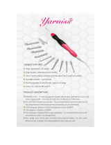
2. DESCRIPTION
Embroidery machine makes the braiding stitch and also can make the single
thread chainstitch, the tape attaching, the ray stitch and pile or moss stitch. It is
designed for ornamenting or embroidering ladies’ cloaks and suits, millinery,
uniforms, draperies, table cover, etc.
The read may be of cotton, wool, worsted, silk, metal and other threads of similar
adaptability. A large variety of fabrics can be embroidered, ranging from fine chiffon
to china silk and cloth.
The usual method of producing embroidered designs is to follow a pattern that
has been perforated, stamped or traced on the fabric, but with practice the operator
can produce embroidery designs without premarking the fabric.
3. SPEED
When first operating this machine, the best results can be obtained by running
the machine approximately 800 stitches per minute. The speed can be increased
as the operator becomes more proficient and nature of the work permits.
2

4. TO OIL THE MACHINE (Fig. 1, 2, 11 & 12)
To insure easy running and prevent unnecessary wear of the parts which are in
movable contact, the machine requires oiling.
Oil should be applied to the places designated by unlettered arrows in Fig.
1,2,11and 12.
3

Fig. 2 shows the arm cover removed for the purpose of oiling. This arm cover can
be removed after taking out thumb screw, Fig. 10. If the machine is used
continuously, oil should be applied at least once each day.
5. NIPPLES, NIPPLES AND THREAD (Fig. 3)
Needles for embroidery machine are system 137 x 1 and are available in sizes
from 1 to 12. These needles have hooks similar in appearance to those of hand
crochet needles.
The needle must be selected according to the thickness and the style of the
thread to be used. The thread must not only fill the opening of the hook in the
needle but must slide freely therein.
To correspond with the needle used in the machine a suitable nipple must be
selected, as the needle in forming the stitch has to operate through the nipple. The
4

needle must fit in the nipple and slide freely without side play. Nipples are available
in size numbers similar to those of the needles, and for general work the number of
the nipple should be the same as that of the needle.
The nipples for embroidery machine are available in the following kinds, as per
Fig. 3.
(a) : For chainstitch and moss stitch
(b) : For tape attaching
(c) : For braiding stitch and ray stitch
6. TO REMOVE, REPLACE AND SET NEEDLE AND NIPPLE (Fig. 4)
When it is necessary to change the needle and nipple on the machine, first select
another needle and corresponding nipple. Then lower the presser foot lifter (J),
loosen screw (B) and remove needle bar (A) and needle from top of machine.
Remove nipple holder (O), loosening screw by screwdriver.
Select the correct needle hole in needle plate (D).
NOTE: The needle hole should be slightly larger than the needle, so that the
5

needle, when laid around the needle, will have sufficient space to pass
without touching the sides of the needle hole.
Loosen thumb screw (L) and turn plate (D) until correct needle hole is in line with
needle, then tighten thumb screw (L).
Next, insert the selected nipple (N) into the lower part of nipple holder (O) and
tighten screw securely with the screwdriver, Insert the nipple holder (O) into the
nipple carrier (Fig. 3) and tighten screw securely. Screw selected needle into
needle bar (A) and tighten with pliers provided. Replace needle bar (A) down into
sleeve and adjust its height so that the fabric to be embroidered can just pass under
the point of the needle.
Be sure handle (K) is as far to the front as possible and that the hook of the
needle faces the front. Then tighten screw (B), which also should face the front.
NOTE: Do not tighten screw (B) except when needle bar (A) is in its place. If the
screw is tightened when needle bar (A) is not in its place, needle bar operating
collar is transformed and needle bar does not enter into the collar.
6

A. Needle bar
B. Needle bar operating collar set screw
C. Presser foot slide bar thumb screw
D. Needle plate
E. Tension regulating lever
F. Tension regulating plate
G. Tension complete
H. Tension bracket
I. Tension controller spring
J. Presser foot lifter
K. Stitch rotating hand lever handle
L. Needle plate thumb screw
M. End of looper shaft
N. Nipple
O. Nipple holder
P. Nipple carrier thumb screw
7. TO THREAD THE MACHINE (Figs. 5, 6 & 7)
1) For the thread (Figs. 5 & 6)
Place the cone of thread in a convenient position on the floor.
Three thread eyelets are furnished with the machine. These eyelets should be
fastened to the underside of the table as shown at (1), (2) and (3), Fig. 5. Eyelet (1)
should be located directly above the cone of thread.
Pass the thread up from the cone and through eyelets (1), (2) and (3), then
through hole (1), over between tension discs (5), through thread controller spring
(6). Turn handle (A), Fig. 6 to the front or slightly to the left, raise presser foot and
insert threading wire (B) in the forward hole (7) of needle plate. With the left hand,
catch thread on hook of threading wire (B) and draw wire and thread up through
hole needle plate. With the left hand, hold end of thread with a slight tension.
7

With the right hand, turn handle (A) straight to the left, having started the
machine, quickly bear down and up on handle (A) so the needle will pick up the
thread for one stitch. Keep handle (A) in same position and with the threading wire
(B), draw thread directly toward you, laying end of thread loosely on needle plate
after t comes up thread needle hole.
2) For the cord (Fig. 7)
Wind the cord
on the cord spool , using the spool winder spindle on the
pulley. Place it on the cord spool bracket
. Inter the cord into the top of needle
bar
with the threading wire (large) and pass it below the end of nipple
carrier 6, then through to the hole of the nipple
.
3) For the braid (Fig. 7)
Wind the braid
on the braid spool , using the spool winder spindle on the
pulley. Place it on the braid spool bracket
. Pass the braid through the braid
guide
of the bracket and through the hole of the braid leader rod and
the hole
of the braid leader bracket, then through the forward hole of the
braid leader guide.
Now the machine is ready for operation.
8

9

8. LEARNING TO OPERATE THE MACHINE (Fig.8)
Note: When in operation the machine pulley must always turn over away from
operator.
Mark a design (see Fig.8) on 30cm (12 inch) square piece of cloth. Place cloth
under presser foot so that the nee
dle will enter cloth as at point 1. Turn handle
,
ig. 6 to the right and the hook of the needle will be turned in the same direction.
F
Lower presser foot, start machine pulley by turning it over away from you, grasp
handle
and pull it down to start the machine. With handle pressed and to the
right, cloth will be fed to point
, then turn handle to the front and cloth will be fed
to point
turn handle to the left and cloth will be fed to point etc.
To stop machine raise handle
. Machine will stop with needle as its highest
point.
ld practice embroidering designs similar to those illustrated
below.
These designs can be sketched on white material such as lawn, and by following
them, the operator can soon become proficient enough to attempt more intricate
e
9. TO OPERATE THE MACHINE (Fig. 9)
The operator shou
d signs or patterns.
10

10. TO REGULATE THE PRESSURE ON THE PRESSER FOOT (Fig.4)
sser foot is regulated by the thumb screw
The pressure on the pre
, Fig.4. To
crease the pressure, turn the thumb screw over to the right or downward. To
de
m
The tension on the thread is regulated by the thumb nut
in
crease the pressure, turn the thumb screw over to the left or upward.
11. TENSIONS (Fig.5)
If stitches are too tight, raise needle bar approximately 1.5 /m (1/16 inch).
Various effects can be produced by changing the height of the needle bar as well
as by adjusting the length of stitch.
, Fig. 5 at the left of
e tension discs. To increase the tension turn this nut over toward you. To
ecrease the tension turn this nut over from you . this tension should be only tight
nough to prevent the skipping of stitch.
th
d
e
11

12. TO ADJUST THE LENGTH OF STITCH (Fig. 10)
The length of stitch is adjusted by screw
, Fig. 10. To lengthen the stitch,
osen locking lever
and turn screw
lo
over to the left or upward, then tighten
locking lever
.
shorten the stitch, loosen locking lever
To
and turn the screw over to the
right or downward, then tighten locking lever
.
EGULATE THE PRESSURE ON THE NIPPLE (Fig.10 & 11)
13. TO R
, Fig. 10 at
The pressure on the nipple is regulated by the thumb screw
the top
f the machine. To increase the pressure, turn this thumb screw over to the right or
ing the needle plate.
o
downward. To decrease the pressure, turn this thumb screw over to the left or
upward.
Note: Too much pressure on the nipple may cause the thread to break.
When sewing fine net, it is sometimes necessary to prevent the nipple from
touch
12

To raise the nipple, insert a screwdriver in hole , Fig. 11 and loosen the set
screw therein. The eccentric adjusting stud
can then be turned by the wrench
provided so that nipple can be set at desired height, then tighten the set screw in
hole
.
otion to throw the machine out of action and make sure that it is
securely held in its looking position. Raise the needle holder to avoid breaking the
fter removing the thumb screw
14. THE LOOPER (Fig. 12)
Allow the stop m
point of the needle, remove the needle plate a
,
ig. 12, and observe the notch in the looper which, when in its correct position,
sh ,
F
ould be at the rear slightly to the right of the needle while the handle
toward the front.
is
13

15. TO SET THE LOOPER (Fig. 4 & 12)
Turn the machine back on its hinges and turn handle
, Fig. 12 and screw ,
Fig. 4 to the front. Loosen set screw
, Fig. 12 of the operating worm gear .
And turn the gear slightly, until the notch in the looper is in its correct position as
instructed above. After having set the worm gear flush with the end of the looper
shaft
, tighten the set screw .
UST THE NUMBER OF THE BRAIDING (Fig. 10)
r
16. TO ADJ
The number of the braiding can be adjusted by the leve
, Fig. 10, which is
lo e gears do not engage
an titch or tape attaching
em
tch
In case iding (roll) per one stitch
The bigger the number is set, the coarser the internal of the braiding will be.
cated on the top of the machine frame. At the number 0, th
d the machine will be operated as chainstitch, moss s
broidery.
In case of the number 1, one braiding (roll) per one stitch
In case of the number 2, 1/2 braiding (roll) per one sti
In case of the number 3, 1/3 braiding (roll) per one stitch
of the number 4, 1/4 bra
Therefore, set the number 1 for normal braiding stitch.
14

Note: Do not change the lever while the clutch is engaging. If do so, it may cause
m works that the braid spool
racket
the machine to damage.
17. TO ADJSUT THE TENSION OF THE BRAIDING (Fig. 10)
It is the best for the nor al braiding embroidery
b
, Fig. 10 is set in the left while the handle is at the front.
To adjust as above, bring the handle
to front, hold the handle by the knee as
it does not tu
rn round, then press the gear changing lever
, Fig. 10 to right and
rn the braid spool bracket
to the above position.
ket
tu
To increase the tension of the braiding, turn the braid spool brac
over from
ou. To decrease the tension to the braiding, turn the braid spool bracket
y
over
If the gears do not engage after the above adjustment, hold the braid spool
toward you.
bracket
by the left hand and turn the pulley by the right hand.
Note: Do not press the gear changing lever
while the clutch is engaging. If
do so , it may cause the machine to damage.
The additional adjustment will be made by the braid spool adjusting thumb nut
, Fig. 7 and the braid leader guide , Fig. 10.
18. RAY STITCH (Fig. 4 & 7)
The ray stitch can be done by adjusting the tensions of the thread loose, the
tensions of the cord and the braid slightly tight as you like.
(1) d
n the screw
For loosening threa (Fig. 4)
Loose
, Fig. 4 and lift the needle bar so that the thread
15

loosens.
(2) (F
n the screw
For tightening cord ig. 7)
Tighte
, Fig. 7 so that the rotation of the cord spool becomes
low.
) For tightening braid (Fig. 7)
Tighten the screw
s
(3
, Fig. 7 so that the rotation of the braid spool becomes
slow.
Then, set the lever
, Fig. 10 to the number 1.
19. PILE OR MOSS STITCH (Fig. 4, 10 & 12)
The raised pile or moss stitch is produced by adjusting the machine so that it will
drop the stitches in loose loops on the materials. To accomplish this, turn handle (K),
Fig. 4 to the front, loosen
the screw (B) and turn the needle bar (A) so that the hook
f the needle will point directly to the back of the machine, then tighten the screw
(B
o
). Reach under the bed of the machine with the left hand, grasp the knurled end
, Fig. 12 of the operating worm gear draw the worm gear to the left and while
holding it turn handle
around to the right directly to the back, then release the
knurled
end of the gear.
ir
The looper will then be set in the opposite d ection to that which is required for
the chain stitch, or with the notch of the looper at the front of the needle while
handle
, Fig. 10 is at the front. Change the presser foot to the presser foot
(spur).
By operating the machine and turn handle
rapidly, so
circles of dropped stitch loops laid one on the other, raised pil
as to make very small
e work is produced.
he higher the needle is set the longer the loop will be. The size of the thread and
thickness of the material used will have to be considered when adjusting the
machine for pile stitching.
T
16

1. MACHINE FRAME & COVERS COMPONENTS
17

REF. NO
.
PARTS NO
.
P1-1 AM1114-10 MACHINE FRAME
P1-2 8181 ARM TOP SCREW
P1-3 8470 ARM HEAD COVER
P1-4 5227 ARM HEAD COVER THUMB SCREW
P1-5 8466-
A
SPOOL CARRIER DRIVING GEAR COVER
P1-6 4015 SPOOL CARRIER DEIVING GEAR COVER SET SCREW
P1-7 8434 ARM SIDE COVER
P1-8 8150 ARM SIDE COVER POSITION PIN
P1-9 8483 ARM SIDE COVER THUMB SCREW
P1-10 S-8445 CORD SPOOL BRACKET SUPPORTING ARM WITH NEEDLE BEARING
P1-11 8172 CORD SPOOL BRACKET SUPPORTING ARM CLAMP SCREW
P1-12 8146 CORD SPOOL BRACKET SUPPORTING ARM POSITION PIN
DESCRIPTION
18

3. ARM SHAFT MECHANISM COMPONENTS
19
/