Page is loading ...

OPERATOR’S MANUAL
650502-X-B
RELEASED: 4-16-99
REVISED: 5-28-10
(REV. E)
INCLUDING: OPERATION, INSTALLATION & MAINTENANCE
FOR USE WITH CONVENTIONAL HVLP / AIR SPRAY SYSTEMS
(SPRAY GUN NOT INCLUDED)
650502-B, 650502-1-B
ALSO INCLUDE MANUALS: 66605X-X DIAPHRAGM PUMP (PN 97999-099), 650789-X DIAPHRAGM PUMP (PN 97999-818), 2752X-X
MATERIAL REGULATOR (PN 97999-674), P292X1-XXX PIGGYBACK FILTER / REGULATOR (PN 100400-8), P291XX-XXX MODULAR
FILTER / REGULATOR (PN 100400-24).
1/2” DIAPHRAGM PUMP, 1:1 RATIO, 5 GALLON CONTAINER
LOW PRESSURE DELIVERY SYSTEM
READ THIS MANUAL CAREFULLY BEFORE INSTALLING,
OPERATING OR SERVICING THIS EQUIPMENT.
It is the responsibility of the employer to place this information in the hands of the operator. Keep for future reference.
SERVICE KITS
Use only genuine ARO replacement parts to assure compatible pres-
sure rating and longest service life.
• Fluid Section Repair Kit 637140-A4.
• Air Section Repair Kit 637141.
Refer to the 66605X-X Operator’s Manual for parts / repair and service
information.
PUMP SYSTEM DATA
Model 650502-X-B Low Pressure Delivery System................
Pump Model 650789-2A4..........
Pump Type Non-Metallic Air Operated Double...........
Diaphragm with stainless steel seats
Material Groundable Acetal.....................
Weight 19.4 lbs (8.8 kg) (650502-B)....................
23.57 lbs. (10.7 kg) (650502-1-B)
Air Inlet 1/4” - 18 n.p.t.f......................
Air Consumption 1 c.f.m. per gallon (approx.)..............
Maximum Air Inlet Pressure 100 p.s.i.g. (6.9 bar)......
Maximum Material Inlet Pressure 10 p.s.i.g. (0.69 bar)..
Maximum Outlet Pressure 100 p.s.i.g. (6.9 bar).......
Maximum Flow Rate 13 g.p.m. (49 l/m)...........
Maximum Particle Size 3/32” (2.4 mm).........
Maximum Output Per Cycle .039 gallons (148 cc’s)......
Maximum Temp. Limits 10_ to 180_F(-12_ to 82_C).........
Dimensional Data See page 3.............
Noise Level @ 70 psi, 60 C.P.M.h 71.1 db(A)..
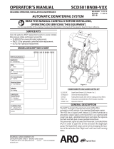
A
FIGURE 1
B
C
D
E
F
h The pump sound pressure levels published here have been updated to an Equivalent Continuous Sound Level (L
Aeq
) to meet the intent of ANSI S1.13-1971, CAGI-PNEUROP S5.1 using four microphone locations.
MAJOR COMPONENTS LIST
* Operator’s Manuals are provided, which cover parts and service information.
Item Description Qty Part No. Item Description Qty Part No.
A Modular Piggyback* (1) P29221-210 D 1/2’’ Diaphragm Pump* (1) 650789-2A4
B Modular Filter / Regulator* (1) P29122-100 E Cover Assembly (1) 66971
C 1/4 Sst / Carbide Regulator* (1) 27520-400 F Agitator Asm. (650502-1-B only) (1) See parts list
GENERAL DESCRIPTION
The 650502-X-B Portable Pumping System includes fittings, drum cov-
er, regulators, siphon tube, gauges and hardware. It is intended to be
usedin conventional HVLP (HighVolume Low Pressure) spraysystems.
These systems generally operate using low material pressure (less than
30 p.s.i.), and when complimented with the proper gun, it produces a
‘‘soft spray”.
Read the information included with the spray gun for system settings
and operation information.
The diaphragm pump uses stainless steel balls and seats, and PTFE di-
aphragms and is designed to be used with waterborne paints. The gun
and low pressure air and material hoses are not included. (Continued)
INGERSOLL RAND COMPANY LTD
209 NORTH MAIN STREET – BRYAN, OHIO 43506
(800) 495-0276 FAX(800) 892-6276
© 2010
www.ingersollrandproducts.com
CCN 99800609

PAGE 2 OF 4
650502-X-B
PARTS LIST / 650502-B, -1-B
Item Description (Size in inches)
Qty
Part No. Item Description (Size in inches)
Qty
Part No.
1 Plug (Agitator) (models 650502-B)(not shown) (1) 91143
2 Bracket (1) 94825
3 Fitting (3/8” - 18 n.p.t.f. - 1 x 1/4” - 18 n.p.t.f. - 1) (1) 90538
4 Adapter (1/4” - 18 n.p.t.f. - 1) (2) 1950
6 Gauge (0 - 160 p.s.i.) (1) 100091
7 Coupling (1/4” - 18 n.p.t.f. - 1)(models 650502-B) (1) Y43-42-C
8 Tee (1/4” - 18 n.p.t.f. - 1 male) (1) 94039
9 Gauge (0 - 30 p.s.i.) (1) 93769
10 Thumb Screw (3) 94078
11 Nut (1) 104173
13 Elbow (1/4” - 18 n.p.t.f. - 1) (1) 3383
14 5 Gallon Pail (1) 93184
15 Fitting (1/2” - 14 n.p.t.f. - 1 x 1/4” - 18 n.p.t.f. - 1) (1) 94041
f 16 Tubing (5/16” o.d. x 9” long) (1) 94980-XXX-X
17 Siphon Tube (1) 93773
18 Hex Cap Screw (1/4”-20x1”) (4) Y6-45-T
19 Washer (.281” i.d. x .625” o.d.) (4) 93096
20 Nut (1/4” - 20) (4) Y12-4-S
21 Screw (5/16” - 18 x 5/8”)(not shown) (1) Y8-58-S
22 Nut (5/16” - 18)(not shown) (1) Y12-5-S
23 Gauge (0 - 160 p.s.i.) (1) 29850
24 Shut-Off Valve (1/4” - 18 n.p.t.f. - 1) (1) Y28-1
25 Male Connector (5/16” o.d. tube -- 1/4” - 18 n.p.t.f. thd) (1) 59474-158
26 Male Elbow (5/16” o.d. tube - 1/4” - 18 n.p.t.f. thd) (1) 59756-158
27 Valve Assembly (1/4” - 18 n.p.t.f. - 1) (1) 104174-2
28 Ground Kit Assembly (not shown) (1) 66885-1
K 650502-1-B Agitator Components
fK 29 Tube (1/4” o.d. x 6” long) (1) 59675-XXX-X
K 30 Male Elbow (1/4” o.d. tube - 1/8” - 27 n.p.t.f. thd) (2) 59756-56
K 31 Regulator (1) 104104-N01
K 32 Nipple (1/8” - 27 n.p.t.f. - 1) (1) Y237-2
K 33 Agitator Motor (1) 650252
K 34 Hose Clamp (1) 75923
K 35 Stirring Rod (12”) (1) 92094-4
K 36 Adapter (1) 75895
K 37 Set Screw (1/4” - 20 x 1/4”) (4) Y29-42-S
K 38 Propeller (1) 94783-1
f Tube is available in bulk quantities only.
GENERAL DESCRIPTION (CONTINUED)
Consult your sales representative for the proper low pressure gun and
other accessories which will best match the application.
The drum cover features a mount for locating an agitator (pn 651100),
which is available separately.
Theory of operation:
HVLP (High Volume, Low Pressure) is a spray process which uses a
high volume of air (15 - 22 c.f.m.) at a low pressure (10 p.s.i. or less) to
atomize the material, producing both high transfer efficiency (the total
percent of material that actually stays on the intended surface) and a
quality finish. The air cap of the HVLP gun injects air into the fluid after it
passes through the orifice restriction. The low velocity of the material be-
ing sprayed minimizes the over-sprayand bounce-back that is associat-
ed with conventional air spray.

PAGE 3 OF 4650502-X-B
PARTS LIST / 650502-B, -1-B
16-1/2”
(419 mm)
30-5/8”
(778 mm)
12-3/4”
(324 mm)
SPRAY GUN AIR
REGULATOR AND GAUGE
PUMP AIR
REGULATOR
AND GAUGE
LOW PRESSURE
MATERIAL GAUGE
MATERIAL PRESSURE
REGULATOR
AIR
SUPPLY
REFER TO INSTRUCTIONS
INCLUDED WITH SPRAY GUN
HIGHER
(CLOCKWISE)
LOWER
(CTR-CLOCKWISE)
MATERIAL OUTLET
TO SPRAY GUN
REGULATED AIR
TO SPRAY GUN
16
25
30
13
3
29
31
33
34
36
37
35
9
1523
10
14
17
38
26
32
20
19
18
24
2 727
8
6
11
4

PAGE 4 OF 4
650502-X-B
OPERATING INSTRUCTIONS
WARNING
DO NOT EXCEED MAXIMUM OPERATING PRES-
SURE OF 100 P.S.I. (6.9 BAR) AT 100 P.S.I. (6.9 BAR) AIR INLET
PRESSURE.
WARNING
READ THE PUMP MANUAL FOR ADDITIONAL
OPERATING AND SAFETY PRECAUTIONS AND OTHER IM-
PORTANT INFORMATION.
INITIAL SETUP PROCEDURE
NOTICE
REFER TO THE INFORMAT ION INCLUDED WITH THE LOW PRES-
SURE HVLP GUN FOR SYSTEM SETUP INFORMATION. THE SYS -
TEM IS INTENDED FOR LOW PRESSURE APPLICATION ONLY.
• Attach air supply hose, gun and low pressure material hose.
• Install the connector to the air supply hose.
• Attach (28) ground kit to ground tab, securing with (21) screw and
(22) nut.
• Attach the ground wire to a suitable ground.
• The gun air supply hose must be 5/16” i.d. minimum.
• Keep containers covered to prevent contamination.
• When using an agitator, install a “T” at the air inlet or use a separate
air supply source.
Nominal system settings:
• Pump Outlet Material Pressure - 15 p.s.i. maximum.
• SprayGun Air Pressure - 60 p.s.i. maximum. Note: At 30 p.s.i. nomi-
nal setting it will deliver approximately 8 p.s.i. at the air cap when us-
ing 5/16” i.d. x 15’ long air hose.
• Set air pressure to the pump at approximately 2x (two times) the op-
erating material pressure.
For example: If 15 p.s.i. material pressure is required, adjust the
pump air regulator / gauge pressure to approximately 30 p.s.i. Use
the material pressure regulator to adjust. Control the spray gun air
volume using the air regulator.
START-UP
1. Turn the knob on the air regulator counterclockwise to zero p.s.i.
2. Place pump and cover (with gun and hose attached) onto the con-
tainer of material.
3. The operating pressure should be set at the lowest needed to atom-
ize and deliver the paint. Start with the gun material pressure about
the same as the air supply and adjust up or down to set the pattern.
4. Start the pump to cycle by turning the air regulator knob clockwise.
The pump will cycle several strokes until pressure is built up in the
system, at which time it will stop. Check for any loose fittings or leak-
age.
PN 97999-823
/