Page is loading ...

Tools and Materials
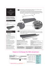
Before You Begin
WARNING: Risk of serious injury. Damage prior to installation can result in glass shattering.
Inspect the glass and all parts for damage before installation.
WARNING: Risk of serious injury. Improper installation can result in glass shattering. Follow all
installation instructions.
NOTICE: Do not touch the edges of the tempered glass with tools or any other hard objects. Do not set
the unframed tempered glass directly on the floor or any hard surface.
WARNING: Risk of serious injury. Do not cut tempered glass. Tempered glass will shatter if cut.
WARNING: Risk of serious injury. Shower door and side panels can shatter. Regularly inspect the
glass and all parts for damage, missing, or loose parts.
WARNING: Risk of serious injury. Always wear safety glasses while cutting and drilling.
IMPORTANT! Leave this manual for the end user. Read these instructions before installing or using this
product.
WARNING: Risk of personal injury. Do not cut the tempered glass. If the glass is cut, the glass
will shatter and may cause personal injury.
IMPORTANT! This door is designed to accommodate walls that are less than 3/8″ (1 cm) out of plumb.
Verify the area the door will be attached to is within 3/8″ (1 cm) or better of plumb. The door may not
function properly if the wall is more than 3/8″ (1 cm) out of plumb.
Your new Sterling door can be installed with the door opening to either the right or left. Install the
door with the pivot side away from the showerhead for best results.
Before starting the installation, lay out and identify all of the parts. Inspect for damage.
During the installation, protect the floor of the shower with a drop cloth to avoid damage.
The shower receptor should be installed and prepared at this time, including finished wall materials.
Closely follow the instructions pertaining to the sealant application on the door. Sealing areas other
than those shown may cause leaking.
Two people should perform this installation.
Safety Glasses
Level
Caulk Gun
File
Knife
Miter Box
Plus:
Drop Cloth
Pencil & Felt
Tip Marker
Claw
Hammer
Tape
Measure
Masking
Tape
Silicone
Sealant
Center
Punch
Drill and
Assorted
Drill Bits
Miter Saw or Hacksaw with
32 Teeth per Inch Blade
Assorted
Screwdrivers
1034028-2-H 2 Sterling

Determine the Door Configuration
IMPORTANT! Install the pivot side of the door on the side opposite the showerhead.
Determine whether the door will pivot on the right or left side.
Make sure the door can swing freely in the chosen configuration.
Sterling 3 1034028-2-H

Parts Identification
Filler Jam
Wall Jamb
Hinge Jamb
Hinge
Door Panel Assembly
Strike Jamb
Wall Jamb
Towel Bar
Bottom Seal
Bottom Track
Hinge Jamb Cap
Strike Jamb Cap
Wall Jamb Cap
Wall Jamb Cap
Strike Side Wall Jamb
1034028-2-H 4 Sterling

1. Measure and Cut the Bottom Track
IMPORTANT! Risk of product damage. If your shower has a curve in the corners where they meet the
sidewalls, be sure to measure from wall to wall above the curves. Failure to measure above the curve or
angle could result in the bottom track being cut too short.
Carefully measure the width (distance D) of the finished opening.
Consult the chart below to determine whether or not your installation will need a filler jamb.
Model # Dimension D Filler Jamb Required?
65**-30 27-1/2″ (69.9 cm) - 29-1/2″ (74.9 cm) Not needed
65**-30 29-1/2″ (74.9 cm) - 30-1/2″ (76.2 cm) Needed
65**-33 30-1/2″ (76.2 cm) - 32-1/2″ (82.6 cm) Not needed
65**-33 32-1/2″ (82.6 cm) - 33-1/2″ (85.1 cm) Needed
65**-36 33″ (83.8 cm) - 35″ (88.9 cm) Not needed
65**-36 35″ (88.9 cm) - 36″ (91.4 cm) Needed
65**-39 36-1/2″ (92.7 cm) - 38-1/2″ (97.8 cm) Not needed
65**-39 38-1/2″ (97.8 cm) - 39-1/2″ (100.3 cm) Needed
NOTE: If dimension ″D″ falls in a range that can be either with or without the filler jamb, use the filler
jamb in your installation.
If your installation does not require a filler jamb, subtract 2-3/4″ (7 cm) from dimension ″D″ and cut
the bottom track to this dimension. For best results, use a 32-teeth hacksaw blade and a miter box.
If your installation does require a filler jamb, subtract 3-3/4″ (9.5 cm) from ″D″ and cut the bottom
track to this dimension. For best results, use a 32-teeth hacksaw blade and a miter box.
Important: Measure carefully. If your walls are
curved or angled, measure above the curve or
angle. Failure to do so can result in an improperly
cut bottom track.
Measure
here.
Measure
here.
Measure distance "D"
above curves in the
corners.
Angled
Base
Curved
Base
D
Bottom Track
Shower Ledge
Front Edge
Inside of Shower
Sterling 5 1034028-2-H

Measure and Cut the Bottom Track (cont.)
File the rough edges smooth where the bottom track was cut, taking care to avoid damaging
finished surfaces.
NOTE: If there are curves where the sidewalls meet the threshold, contour the wall jamb edges to match
the curves.
Locate the bottom track on the shower ledge. It should be located on the flattest part of the ledge.
Position the bottom track so the gaps between the track and the wall are identical at both ends.
Make sure the bottom track is placed so it is an equal distance from the front edge of the shower
ledge at all points.
1034028-2-H 6 Sterling

2. Install the Adjustment Clamps
Insert four adjustment clamps into each wall jamb as shown (eight total).
Partially thread the provided #8-18 x 1/2″ panhead screws through the pre-drilled holes in the wall
jambs and into each adjustment clamp using a Phillips screwdriver. Do not tighten the screws at this
time.
Note:
Do not fully
tighten screw.
Adjustment Clamp
#8-18 x 1/2" Screw
Wall Jamb
Wall Jamb
Top View
Wall Jamb
#8-18 x 1/2" Screw
Sterling 7 1034028-2-H

3. Install the Wall Jambs and Optional Filler Jamb
Drill the Installation Holes
With a pencil, mark the location of the wall jamb on the shower wall. Measure evenly on both sides.
Place the wall jamb against the wall and check for plumb with a level. The side of the wall jamb
with the adjustment clamps attached to it should be located to the inside of the shower.
Make a pencil mark at each of the four pre-drilled holes in the wall jamb and remove the wall jamb.
NOTE: When installing on ceramic tile, use a center punch to nick the surface of the glaze. Tap the center
punch lightly with a hammer to avoid cracking the tile.
Drill each hole with a 5/16″ drill bit (use a masonry bit for ceramic tile).
Install the Anchors
Push (1) the middle of anchor in and fold (2) the outside edges down.
Insert (3) an anchor in each hole.
Repeat for all the anchors.
Install the Wall Jambs
If your installation requires a filler jamb, position the filler jamb over the holes.
Secure a wall jamb in place (over the filler jamb if needed) using four provided panhead screws.
Repeat for the other wall jamb, skipping filler jamb procedures.
Remove the bottom track and thoroughly clean the shower ledge.
Wall Jamb
Wall Jamb
Top View
Wall Jamb
#8-18 x 2"
Panhead Screw
Filler Jamb
Filler Jamb
With Filler Jamb
Without Filler Jamb
Anchor
Drill holes.
3
2
1
Adjustment Clamp
1034028-2-H 8 Sterling

4. Caulk and Install Bottom Track
Insert the bottom track and check for proper fit. The lip of the bottom track should face toward the
outside of the shower. The ends of the bottom track should fit snugly against the front protrusions
in the wall jambs.
Remove the bottom track and apply silicone sealant in the groove at the bottom front edge of the
bottom track.
Install the bottom track.
5. Assemble the Hinge Jamb
Lay the hinge jamb on the floor or on a workbench. Use a drop cloth to protect the product finish.
Insert the front side of the hinge into the slot on the hinge jamb.
Secure the hinge to the hinge jamb using four provided flathead screws. Make sure the edge of the
hinge is flush with the edge of the hinge jamb before tightening the screws.
Apply sealant.
Note:
Use silicone
tub & tile type caulk.
Bottom Track
Bottom Track
Wall
Jamb
Flathead Screw
#8-18 x 1/2"
Hinge
Hinge
Hinge Jamb
Hinge Jamb
Hinge Jamb
Insert the hinge
into the slot
making sure the
edges are flush.
Sterling 9 1034028-2-H

6. Install the Hinge to the Door Panel
NOTE: Leave a small gap on the handle side of the door for clearance from the strike jamb. The door will
not close properly without this gap.
Align the slotted holes on the hinge with the channel in the door panel. Make sure the top edge of
the hinge assembly is flush with the top of the channel.
Secure the hinge to the door panel using four of the provided #10-16 x 3/8″ truss head screws.
Install the hinge jamb cap on the top of the hinge jamb where it aligns with edge of door.
Bottom Seal
Bottom View
Hinge Jamb Cap
Door Panel
Door Panel
Hinge Assembly
Hinge Jamb Cap
Hinge Jamb
Cap
Assemble, making sure
top edges are flush.
#10-16 x 3/8"
Truss Head Screw
1034028-2-H 10 Sterling

7. Install the Flat Seal
Slide the seal into the door panel seal holder with the fabric edge out.
Install the seal channel to the base of the door panel with the four provided #6-20 x 1/4″ panhead
screws.
Trim off any excess seal using a utility knife.
Pull out any fabric threads that jut out horizontally from the seal.
Fabric Seal
Seal Channel
Fabric Seal
Seal Channel
#6-20 x 1/4"
Panhead Screw
Pull out horizontal
threads.
Note:
Cut off excess
fabric seal length.
Sterling 11 1034028-2-H

8. Install the Strike Side Wall Jamb and Magnet
Push the strike jamb into the appropriate wall jamb with the wide lip facing toward the inside of
the shower. Each slot in the strike jamb will slide over the screw body and fit between the clamp
and wall jamb.
Secure the strike jamb to the wall jamb by tightening the #8-18 x 1/2″ panhead screws in the
adjustment clamps until snug.
Install a strike jamb cap on the top opening of the strike jamb.
IMPORTANT! The strike jamb magnet is the longer of the two supplied magnets.
Install the strike jamb magnet to the contact surface of the strike jamb. The grooved side of the
magnet should face in.
Strike Jamb Cap
Strike Jamb
Wall Jamb
Adjustment
Clamp
Groove Side
of Magnet
Strike Jamb
Longest Magnet
Groove Side In
Magnet
Strike Jamb
1034028-2-H 12 Sterling

9. Install the Door Panel and Magnet
NOTE: You may need to loosen the clamp screws slightly to allow the wall jamb to fit behind them.
Slide the hinge jamb into the other wall jamb. Each slot in the hinge jamb will slide over the screw
body and fit between the clamp and wall jamb.
Tighten the four adjustment screws until snug.
IMPORTANT! The door panel magnet is the shorter of the two supplied magnets.
Install the provided magnet groove side out.
Use a pliers to crimp the bottom end of the door panel groove to secure the magnet.
Reverse for right hinge.
Hinge Jamb
Wall Jamb
Reverse Side
Door Panel
Assembly
If necessary, loosen clamp
screws slightly to fit wall
jamb behind clamps.
Shortest Magnet
Groove Side Out
Sterling 13 1034028-2-H

10. Adjust and Secure the Door
Adjust the door by loosening the jamb screws and shifting the assembly (maximum adjustment is
3/4″ (2 cm) on each side) as needed.
When each side of the door is uniformly aligned and the gap is evenly spaced between the wall
jambs, fully tighten the screws.
11. Install the Handle/Towel Bar
Slide the towel bar onto the towel bar brackets.
Position the towel bar seal on the bottom of the towel bar.
Secure the towel bar with the two provided screws.
Towel Bar
Assembly
Towel Bar Seal
Flathead Screw
#8-18 x 1-1/8"
Towel Bar
Towel Bar
Bracket
Top View
Flathead Screw
#8-18 x 1-1/8"
1034028-2-H 14 Sterling

12. Caulk the Shower Door
NOTE: Follow the silicone sealant manufacturer’s curing instructions before using the shower.
Install the wall jamb caps to the tops of the wall jambs. Flat edges are toward the walls.
Apply silicone sealant to seams where the wall jambs and wall meet on both the outside and inside
of the shower.
Apply sealant to the outside of the shower where the bottom track meets the floor.
Apply sealant to the seam between the bottom track and the wall jamb.
Apply silicone sealant to the seams where the wall jambs and wall
meet on both the outside and inside of the shower.
Wall Jamb
Cap
Wall Jamb Cap
Wall Jamb
Cap
Sterling 15 1034028-2-H

USA: 1-800-STERLING
(1-800-783-7546)
México: 001-877-680-1310
SterlingPlumbing.com
©2014 Kohler Co.
1034028-2-H
/