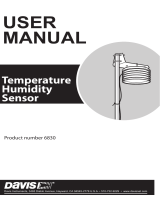
DAVIS Temperature Sensor/Probe Owner's manual

Type
Owner's manual

This manual is also suitable for

DAVIS Temperature Sensor/Probe is an external sensor that can be used to measure outside temperature, soil temperature, or water temperature. It connects to compatible Davis weather stations and displays the temperature readings on the console. The standard version comes with a 40' cable, and the sensor itself is designed to be placed in a location that is not in direct sunlight, has limited exposure to reflected sunlight, and is at least 5 feet from man-made sources of heat.

DAVIS Temperature Sensor/Probe is an external sensor that can be used to measure outside temperature, soil temperature, or water temperature. It connects to compatible Davis weather stations and displays the temperature readings on the console. The standard version comes with a 40' cable, and the sensor itself is designed to be placed in a location that is not in direct sunlight, has limited exposure to reflected sunlight, and is at least 5 feet from man-made sources of heat.

1
External Temperature Sensor Temperature Probe
Installation Manual
The external temperature sensor may be used with the
Weather Monitor II, Weather Wizard III, Weather Wizard II
(S), GroWeather or EnviroMonitor Davis weather stations.
The sensor may be used to measure outside temperature,
though you may bury the sensor or immerse it in water to
measure soil or water temperature instead of air
temperature. The standard version of the sensor comes with a 40' (12 m) cable
.
Tools and Materials Needed
You may need some of the following tools and materials to complete your
in
stallation. Please be sure you have everything you need before beginning.
Shovel or spade to dig hole for sensor if using as a soil temp sensor
Metal or plastic conduit to protect
cable from rodents
Cable clips or weather-resistant cable ties with screw holes or other means for
mounting to secure cable
Testing the Sensor
Test the sensor before installing it.
1. Attach the sensor cable to the appropriate connector on the junction box/
sensor interface
module (SIM). Consult your station manual or installation
manual for more information.
2. Press the appropriate key on your console as necessary to make sure you are
getting an outside temperature reading on the console.
Choosing a Location for the Sensor
Use the suggestions below to find a suitable location in which to mount the
sensor
. Care taken in choosing a location improves the accuracy, reliability, and
durability of the sensor. The ideal location would be on the NORTH SIDE of the
building (south side in the Southern Hemisphere).
Note: When choosing a location for the sensor you should take into consideration the objects
nearby. Objects which heat up in direct sunlight or produce radiative cooling effects may
affect temperature readings by changing the surrounding air temperature.
Look for a location which satisfies the following requirements (Davis’ Radiation
Shield provides additional protection for the sensor):
Place the sensor in a location where it will not be in direct sunlight and whe
re
it will have limited exposure to reflected sunlight.
Limit the exposure of the sensor to the open night sky.
Place the sensor at least 5 feet from man-made s
ources of heat.
Keep the sensor away from AC power lines.
Testing the Sensor
2
If possible, place the sensor at least 5 feet from any surface which is
exposed to direct sunlight because the heat from this surface may affect air
temperature readings in the vicinity.
Place the sensor in a location at least 10 feet away from lights or lamps.
If you are unsure about a location's exposure to the night sky, check for dew
at that location on a light dewy morning. If the area is dry, the location
should work well.
Keep the sensor and most of the cable at least 10 feet
from 110 Vac, 60Hz
utility power. Do not run the sensor cable parallel to house wiring. Mount
the sensor at least 30 feet from high-voltage power lines and transformers.
Typical Weather Wizard II (S), W
eather Wizard III, or Weather
Monitor II Installation
The illustration below shows a typical installation for the Weather
Wizard II (S), Weather Wizard II
I, or Weather Monitor II.
Typical Installation
Typical Standard GroWeather/EnviroMonitor Installation
The illustration on the next page shows a typical installation for the
GroW
eather (used to measure air temperature), Energy EnviroMonitor, or the
Health EnviroMonitor. The sensor cable attaches to connector S2 on the sensor
interface module (SIM). On GroWeather systems, the sensor can also attach to
connector S3 to measure a second temperature (such
as soil temperature).
Testing the Sensor
3
Typical Standard GroWeather/EnviroMonitor Installation
Mounting the Sensor
Depending on your use for this sensor, you may install it following the
suggest
ions below:
For air temperature, use a cable tie, cable clip, or electrical
tape to attach the
cable to a building, post, antenna mast, or other surface (make sure the sensor
itself is not in contact with the building’s surface). Consult the Radiation Shield
manual for instructions on installing the sensor in the Radiation Shield.
For soil temperature, bury the sensor at
a depth suitable for your purposes.
Where the cable runs along the ground, use metal or plastic conduits to protect
the cable from rodents.
For water temperature, drop the sensor int
o the water at a depth suitable for
your purposes. If the cable runs along the ground at any point, use metal or
plastic conduits to protect the cable from rodents.
In any case, to prevent fraying
or cutting of the sensor cable where it is exposed to
weather, it is important that you secure it so it doesn’t whip about in the wind.
For example, you might want to use cable clips or
weather resistant cable ties to secure the cable. Place clips
or ties approximately every 3 to 5 feet (1 to 1.6 m). Do
not
use metal staples or a staple gun to secure cables.
EC EMC Compliance
This product complies with the essential protection requirements of the EC EMC Directive
89/336/EC.
External Temperature Sensor Temperature Probe Installation Manual
Document Part Number: 7395.112 Rev. E, February 20, 2008
Product Number: # 7817
© Davis Instruments Corp. 2008. All rights reserved.
Information in this document subject to change without notice.
Tested to comply
with FCC standards
FOR HOME OR OFFICE USE
3465 Diablo Avenue, Hayward, CA 94545-2778 U.S.A.
510-732-9229 • Fax: 510-732-9188
E-mail: [email protected] • www.davisnet.com
Metal staples—especially when installed with a staple gun—have a tendency
to cut the cables.
Note: When running the sensor cable, try not to tug on the cable in such a way as to loosen
the connections. Also, make sure the sensor cable is not so taut that the connection
may loosen or pull free due to the strain. Many sensor problems occur because cable
connections come loose.
Contacting Davis Technical Support
If you are experiencing problems installing the sensor, first check all cable
connections. Connections should be firmly seated in the jacks and plugged in
straight. If you think a connection may be faulty, try jiggling the cable while
looking at the display. If a reading appears intermittently on the display, the
connection is faulty. If you are unable to solve the problem, please call Davis
Technical Support. We’ll be glad to help. Most questions can be answered over
the phone. You can also email us for support or visit our website. Sorry, we are
unable to accept collect calls.
Note: Please do not return items to the factory for repair without prior authorization.
(510) 732-7814 — Monday - Friday, 7:00 a.m. - 5:30 p.m. Pacific Time. We
are unable to accept collect calls.
(510) 670-0589 Technical Support Fax.
[email protected] — E-mail to Technical Support.
[email protected] — General e-mail.
www.davisnet.com — Davis Instruments web site. See the Weather Support
section for copies of user manuals, product specifications, application notes,
and information on software updates. Watch for FAQs and other updates.
  • Page 1 1
  • Page 2 2
  • Page 3 3
  • Page 4 4

DAVIS Temperature Sensor/Probe Owner's manual

Type
Owner's manual
This manual is also suitable for

DAVIS Temperature Sensor/Probe is an external sensor that can be used to measure outside temperature, soil temperature, or water temperature. It connects to compatible Davis weather stations and displays the temperature readings on the console. The standard version comes with a 40' cable, and the sensor itself is designed to be placed in a location that is not in direct sunlight, has limited exposure to reflected sunlight, and is at least 5 feet from man-made sources of heat.

Ask a question and I''ll find the answer in the document

Finding information in a document is now easier with AI