Page is loading ...

Instruction Manual
748175-G
May 2002
http://www.processanalytic.com
Model 815
Explosion Proof Non-Dispersive Infrared Analyzer

Emerson Process Management
Rosemount Analytical Inc.
Process Analytic Division
1201 N. Main St.
Orrville, OH 44667-0901
T (330) 682-9010
F (330) 684-4434
e-mail: [email protected]
http://www.processanalytic.com
ESSENTIAL INSTRUCTIONS
READ THIS PAGE BEFORE PROCEEDING!
Rosemount Analytical designs, manufactures and tests its products to meet many national and
international standards. Because these instruments are sophisticated technical products, you
MUST properly install, use, and maintain them to ensure they continue to operate within their
normal specifications. The following instructions MUST be adhered to and integrated into your
safety program when installing, using, and maintaining Rosemount Analytical products. Failure to
follow the proper instructions may cause any one of the following situations to occur: Loss of life;
personal injury; property damage; damage to this instrument; and warranty invalidation.
• Read all instructions prior to installing, operating, and servicing the product.
• If you do not understand any of the instructions, contact your Rosemount Analytical representative
for clarification.
• Follow all warnings, cautions, and instructions marked on and supplied with the product.
• Inform and educate your personnel in the proper installation, operation, and maintenance of
the product.
• Install your equipment as specified in the Installation Instructions of the appropriate
Instruction Manual and per applicable local and national codes. Connect all products to the
proper electrical and pressure sources.
• To ensure proper performance, use qualified personnel to install, operate, update, program, and
maintain the product.
• When replacement parts are required, ensure that qualified people use replacement parts specified by
Rosemount. Unauthorized parts and procedures can affect the product’s performance, place the safe
operation of your process at risk, and VOID YOUR WARRANTY. Look-alike substitutions may result
in fire, electrical hazards, or improper operation.
• Ensure that all equipment doors are closed and protective covers are in place, except when
maintenance is being performed by qualified persons, to prevent electrical shock and personal
injury.
The information contained in this document is subject to change without notice.
Teflon and Viton are registered trademarks of E.I. duPont de Nemours and Co., Inc.
Irtran is a trademark of Eastman Kodak Co.
Pyrex is a registered trademark of Corning Glass Works
SNOOP is a registered trademark of NUPRO Co.

Instruction Manual
748175-G
May 2002
Rosemount Analytical Inc. A Division of Emerson Process Management Contents i
Model 815
TABLE OF CONTENTS
PREFACE................................................................................................................................P-1
Definitions ................................................................................................................................P-1
Safety Summary .......................................................................................................................P-2
General Precautions For Handling And Storing High Pressure Gas Cylinders ...............................P-4
Documentation.........................................................................................................................P-5
Compliances.............................................................................................................................P-5
1-0 DESCRIPTION AND SPECIFICATIONS ........................................................................1-1
1-1 General Description......................................................................................................1-1
1-2 Applications..................................................................................................................1-1
1-3 Available Options..........................................................................................................1-2
1-4 Specifications ...............................................................................................................1-3
2-0 INSTALLATION...........................................................................................................2-1
2-1 Unpacking....................................................................................................................2-1
2-2 Location .......................................................................................................................2-1
2-3 Voltage requirements....................................................................................................2-1
2-4 Electrical Connections...................................................................................................2-1
a. Line Power Connections..........................................................................................2-1
b. Recorder Connections.............................................................................................2-1
2-5 Sample Connections .....................................................................................................2-2
2-6 Calibration Gas Connections and Requirements.............................................................2-2
2-7 Sample Handling System..............................................................................................2-4
2-8 Leak Test.....................................................................................................................2-4
2-9 Options ........................................................................................................................2-5
a. Air Purge Kit 652271...............................................................................................2-5
b. Current Output Kit 652269.......................................................................................2-5
c. Case Heater Temperature Control Kit 652270...........................................................2-5
d. Linearizer Kit 652268 ..............................................................................................2-7
e. Motor/Source Assembly Purge Kit 655094................................................................2-8
3-0 OPERATION................................................................................................................3-1
3-1 Initial Startup................................................................................................................3-1
a. Power Verification...................................................................................................3-1
b. Operating Controls and Indicators............................................................................3-1
Digital Display.........................................................................................................3-1
MODE Switch.........................................................................................................3-1
ZERO Adjustment...................................................................................................3-2
SPAN Adjustment ...................................................................................................3-2
3-2 Calibration....................................................................................................................3-3
a. Calibration Procedure..............................................................................................3-3
b. Linearizer Board Calibration.....................................................................................3-3
c. Calibration Curve Construction................................................................................3-4
3-3 Linearization procedure.................................................................................................3-7
3-4 Current Output..............................................................................................................3-9
3-5 Routine Operation.........................................................................................................3-9
3-6 Recommended Calibration Frequency............................................................................3-9
3-7 Shutdown.....................................................................................................................3-9

Instruction Manual
748175-G
May 2002
ii Contents Rosemount Analytical Inc. A Division of Emerson Process Management
Model 815
4-0 THEORY......................................................................................................................4-1
4-1 Detection System Theory ..............................................................................................4-1
4-2 Electronic Circuitry........................................................................................................4-2
a. Oscillator Circuit Board (Schematic 623995) and Associated Elements of Amplitude
Modulation Circuit...................................................................................................4-2
b. Functioning of Modulation System in TUNE Mode.....................................................4-2
c. Functioning of Modulation System in Operating Mode ...............................................4-2
d. Radio-Frequency Demodulator ................................................................................4-3
e. Signal Board (Schematic 652431)............................................................................4-3
f. Power Supply Board (Schematic 624073).................................................................4-3
g. Case Heater Temperature Control Board (Schematic 624003)...................................4-3
h. Current Output Board (Schematic 652439)...............................................................4-3
i. Linearizer Board (Schematic 624674).......................................................................4-4
5-0 TROUBLESHOOTING..................................................................................................5-1
5-1 Symptom Chart.............................................................................................................5-1
5-2 Test Equipment ............................................................................................................5-1
5-3 Voltage Checks ............................................................................................................5-1
5-4 Oscillator Tune Adjustment............................................................................................5-1
5-5 Preamp Gain................................................................................................................5-2
a. Peak AdjusTment....................................................................................................5-2
5-6 Source Balance Shutter Adjustment...............................................................................5-2
5-7 Source Alignment .........................................................................................................5-4
5-8 Source Current Adjustment............................................................................................5-6
5-9 Time Constant ..............................................................................................................5-6
5-10 Case Heater Temperature Control Assembly..................................................................5-6
6-0 ROUTINE SERVICING..................................................................................................6-1
6-1 Cell Removal, Cleaning and Replacement......................................................................6-1
a. Long Cell Configurations .........................................................................................6-1
b. Short Cell Configurations.........................................................................................6-2
6-2 Cell Desiccant ..............................................................................................................6-4
a. Desiccant Replacement...........................................................................................6-4
6-3 Source Replacement.....................................................................................................6-4
6-4 Chopper Motor Assembly..............................................................................................6-5
a. Long Cell Configurations .........................................................................................6-5
b. Short Cell Configurations.........................................................................................6-5
6-5 Detector Replacement...................................................................................................6-6
a. Removal - Long Cell Configurations .........................................................................6-6
b. Removal - Short Cell Configurations.........................................................................6-6
c. Detector Installation................................................................................................6-6
7-0 REPLACEMENT PARTS..............................................................................................7-1
7-1 Circuit Board Replacement Policy..................................................................................7-1
7-2 Selected Replacement Parts .........................................................................................7-1
a. Model 815 Common Parts.......................................................................................7-1
b. Optical Bench.........................................................................................................7-1
7-3 Option Kits ...................................................................................................................7-2
a. Linearizer Kit PN 652268.........................................................................................7-2
b. Current Output Kit PN 652269 .................................................................................7-2
c. Case Heater Temperature Control Kit PN 652270.....................................................7-2
d. Air Purge Kit PN 652271..........................................................................................7-2
e. Motor/Source Purge Kit PN 655094..........................................................................7-2

Instruction Manual
748175-G
May 2002
Rosemount Analytical Inc. A Division of Emerson Process Management Contents iii
Model 815
8-0 RETURN OF MATERIAL ..............................................................................................8-1
8-1 Return Of Material.........................................................................................................8-1
8-2 Customer Service.........................................................................................................8-1
8-3 Training........................................................................................................................8-1
LIST OF ILLUSTRATIONS
Figure 1-1. Model 815 Explosion Proof NDIR Analyzer.......................................................1-1
Figure 2-1. Model 815 Component Locations.....................................................................2-2
Figure 2-2. Power Supply Board.......................................................................................2-3
Figure 2-3. Case Heater Temperature Control Board..........................................................2-3
Figure 2-4. Current Output Board......................................................................................2-6
Figure 2-5. Installation of Current Output and Temperature Control Options.........................2-6
Figure 2-6. Linearizer Board.............................................................................................2-7
Figure 2-7. Signal Board with Linearizer Board Installed.....................................................2-7
Figure 3-1. Model 815 Operating Controls and Indicators ...................................................3-2
Figure 3-2. Signal Board Component Locations .................................................................3-5
Figure 3-3. Linearizer Board Adjustments..........................................................................3-6
Figure 3-4. Typical Linearization Curve..............................................................................3-6
Figure 3-5. Current Output Board......................................................................................3-9
Figure 4-1. NDIR Detection System ..................................................................................4-1
Figure 4-2. Functional Block Diagram................................................................................4-4
Figure 5-1. Modulation System .........................................................................................5-5
Figure 6-1. Optical Bench.................................................................................................6-3
Figure 6-2. Motor/Source Assembly ..................................................................................6-5
Figure 6-3. Detector Replacement.....................................................................................6-7
Figure 7-1. Configurations 06, 07, 11, 19, 21, 31, 36, 41, 45, 54, 71, 72, 81.........................7-3
Figure 7-2. Configurations 35, 73......................................................................................7-3
Figure 7-3. Configurations 64, 83......................................................................................7-4
Figure 7-4. Configuration 08, 10, 12, 13, 18, 32, 39, 42, 43, 55, 63, 65, 67...........................7-4
Figure 7-5. Configurations 22, 23, 29, 30, 33, 34, 38, 76.....................................................7-5
Figure 7-6. Configuration 26.............................................................................................7-5
Figure 7-7. Configurations 74, 82, 84.................................................................................7-6
Figure 7-8. Case Heater Temperature Control Assembly....................................................7-9
LIST OF TABLES
Table 3-1. Typical Linearization Calibration Values ...........................................................3-8
Table 3-2. Linearization Calibration Values.......................................................................3-8
Table 5-1. Troubleshooting Chart.....................................................................................5-3
Table 6-1. Types of Desiccant .........................................................................................6-4
Table 7-1. Configuration Figure List .................................................................................7-2
Table 7-2. Optical Bench Components by Configuration....................................................7-6

Instruction Manual
748175-G
May 2002
iv Contents Rosemount Analytical Inc. A Division of Emerson Process Management
Model 815
LIST OF DRAWINGS (LOCATED IN REAR OF MANUAL)
623995 Schematic Diagram, Oscillator Board
624003 Schematic Diagram, Temperature Control Board
624073 Schematic Diagram, Power Supply Board
624674 Schematic Diagram, Linearizer Board
652258 Installation Drawing, Model 815
652259 Pictorial Wiring Diagram, Model 815
652431 Schematic Diagram, Signal Board
652439 Schematic Diagram, Current Output Board
652446 Schematic Diagram, Zero/Span Control Board
Infrared Calibration and Data Sheet (per application)

Instruction Manual
748175-G
May 2002
Rosemount Analytical Inc. A Division of Emerson Process Management Preface P-1
Model 815
PREFACE
The purpose of this manual is to provide information concerning the components,
functions, installation and maintenance of the Model 815.
Some sections may describe equipment not used in your configuration. The user should
become thoroughly familiar with the operation of this module before operating it. Read
this instruction manual completely.
DEFINITIONS
The following definitions apply to DANGERS, WARNINGS, CAUTIONS and NOTES found throughout
this publication.
DANGER .
Highlights the presence of a hazard which will cause severe personal injury, death, or substantial
property damage if the warning is ignored.
WARNING .
Highlights an operation or maintenance procedure, practice, condition, statement, etc. If not
strictly observed, could result in injury, death, or long-term health hazards of personnel.
CAUTION .
Highlights an operation or maintenance procedure, practice, condition, statement, etc. If not
strictly observed, could result in damage to or destruction of equipment, or loss of effectiveness.
NOTE
Highlights an essential operating procedure,
condition or statement.

Instruction Manual
748175-G
May 2002
P-2 Preface Rosemount Analytical Inc. A Division of Emerson Process Management
Model 815
SAFETY SUMMARY
If this equipment is used in a manner not specified in these instructions, protective systems may be
impaired.
AUTHORIZED PERSONNEL
To avoid explosion, loss of life, personal injury and damage to this equipment and on-site
property, all personnel authorized to install, operate and service the this equipment should be
thoroughly familiar with and strictly follow the instructions in this manual. SAVE THESE
INSTRUCTIONS.
DANGER.
ELECTRICAL SHOCK HAZARD
Do not operate without doors and covers secure. Servicing requires access to live parts which can
cause death or serious injury. Refer servicing to qualified personnel.
For safety and proper performance this instrument must be connected to a properly grounded
three-wire source of power.
This instrument is shipped from the factory set up to operate on 115 volt, 50/60 Hz electric power.
For operation on 230 volt, 50/60 Hz power, see Section 2-3 (page 2-1), Figure 2-2 (page 2-3), and
Figure 2-3 (page 2-3) for modifications.
WARNING .
POSSIBLE EXPLOSION HAZARD
This analyzer is of a type capable of analysis of sample gases which may be flammable. If used for
analysis of such gases the instrument explosion-proof enclosure must be suitable for the gas.
WARNING .
EXPLOSION HAZARD
If explosive gases are introduced into this analyzer, the sample containment system must be
carefully leak-checked upon installation and before initial startup, during routine maintenance and
any time the integrity of the sample containment system is broken, to ensure the system is in leak-
proof condition. Leak-check instructions are provided in Section 2-8 (page 2-4).
Do not operate the Model 815 Explosion-Proof Analyzer without lens cover and door in place with
all bolts secured, unless location has been determined to be non-hazardous.

Instruction Manual
748175-G
May 2002
Rosemount Analytical Inc. A Division of Emerson Process Management Preface P-3
Model 815
WARNING .
HIGH PRESSURE GAS CYLINDERS
This analyzer requires periodic calibration with known zero and standard gases. Refer to General
Precautions for Handling and Storing High Pressure Cylinders, page P-4.
CAUTION .
PARTS INTEGRITY
Tampering or unauthorized substitution of components may adversely affect safety of this product.
Use only factory documented components for repair.

Instruction Manual
748175-G
May 2002
P-4 Preface Rosemount Analytical Inc. A Division of Emerson Process Management
Model 815
GENERAL PRECAUTIONS FOR HANDLING AND STORING HIGH
PRESSURE GAS CYLINDERS
Edited from selected paragraphs of the Compressed Gas Association's "Handbook of Compressed
Gases" published in 1981
Compressed Gas Association
1235 Jefferson Davis Highway
Arlington, Virginia 22202
Used by Permission
1. Never drop cylinders or permit them to strike each other violently.
2. Cylinders may be stored in the open, but in such cases, should be protected against extremes of weather
and, to prevent rusting, from the dampness of the ground. Cylinders should be stored in the shade when
located in areas where extreme temperatures are prevalent.
3. The valve protection cap should be left on each cylinder until it has been secured against a wall or bench, or
placed in a cylinder stand, and is ready to be used.
4. Avoid dragging, rolling, or sliding cylinders, even for a short distance; they should be moved by using a
suitable hand-truck.
5. Never tamper with safety devices in valves or cylinders.
6. Do not store full and empty cylinders together. Serious suckback can occur when an empty cylinder is
attached to a pressurized system.
7. No part of cylinder should be subjected to a temperature higher than 125
°
F (52
°
C). A flame should never be
permitted to come in contact with any part of a compressed gas cylinder.
8. Do not place cylinders where they may become part of an electric circuit. When electric arc welding,
precautions must be taken to prevent striking an arc against the cylinder.

Instruction Manual
748175-G
May 2002
Rosemount Analytical Inc. A Division of Emerson Process Management Preface P-5
Model 815
APPROVED
FM
97-C209
DOCUMENTATION
The following Model 815 instruction materials are available. Contact Customer Service Center or the local
representative to order.
748175 Instruction Manual (this document)
COMPLIANCES
The Model 815 Explosion Proof Non-Dispersive Infrared Analyzer is approved by Factory Mutual for use in
Class I, Groups B, C and D Division 1 hazardous locations.

Instruction Manual
748175-G
May 2002
P-6 Preface Rosemount Analytical Inc. A Division of Emerson Process Management
Model 815

Instruction Manual
748175-G
May 2002
Rosemount Analytical Inc. A Division of Emerson Process Management Description and Specifications 1-1
Model 815
SECTION 1
DESCRIPTION AND SPECIFICATIONS
1-1 GENERAL DESCRIPTION
The Model 815 Non-Dispersive Infrared
Analyzer is designed to continuously
monitor the concentration of a particular
infrared absorbing component of interest in
a flowing gaseous mixture. Concentration is
displayed as a percent of fullscale. Signal
outputs of 0-5 VDC or 0-1 VDC are field
selectable standard.
The Analyzer enclosure is designed to
meet the requirements for Class I, Division
1, Groups B, C, and D, per the National
Electrical Code (ANSI/NFPA 70), and
should be mounted in a weather-protected
area.
1-2 APPLICATIONS
Monitoring applications are found in the
Application Data Sheet which is available
from the local sales office (see Section 8).
Some sample streams contain various
other infrared-absorbing substances, other
than the component of interest. To
minimize interference in such applications,
the instrument may incorporate an optical
filter and, if necessary, a sealed filter cell
containing an appropriate gas charge, as
noted in the Factory Calibration and Data
Sheet located in the rear of this manual.
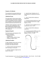
Figure 1-1. Model 815 Explosion Proof NDIR Analyzer
ZERO SPAN
DETECTOR RANGE 1
TUNE RANGE 2
Rosemount Analytical
Model 815
Oxygen Analyzer

Instruction Manual
748175-G
May 2002
1-2 Description and Specifications Rosemount Analytical Inc. A Division of Emerson Process Management
Model 815
1-3 AVAILABLE OPTIONS
Operation of the Model 815 can be enhanced
with the choice of several options, all of which
can be installed in the field after the analyzer
has been ordered.
Signal Linearizer
A signal linearizer kit is available for each
range. Linearizers enable the operator to
convert non-linear output signals into linear
output signals.
Isolated Current Output
The current output option can be field set for
either 4-20mA or 0-20mA, corresponding to
0% to 100% of fullscale. Maximum load is
750 ohms.
Case Temperature Controller
A proportional temperature controller, with
heater and fan assembly, maintains proper
operating temperature inside the case.
Air Purge
The air purge kit is to be installed with
user-supplied components. It is designed for
use in cases where a corrosive gas is either
flowing through the cell or is present in the
environment. The air purge option is provided
for protection of the instrument only, and is
not intended as a safety feature for use in a
hazardous area.
Motor/Source Assembly Purge
This purge is recommended in some
applications to provide a CO2 free, spectrally
constant atmosphere within the Motor/Source
Assembly.
Sample Handling System Accessory
If so ordered, an associated sample-handling
system may be either factory-assembled or
supplied for field installation, depending on
ordering instructions. Sampling systems are
designed on the basis of information furnished
by the customer, which includes a complete
stream analysis. Refer to the Factory
Calibration and Data Sheet in the rear of this
manual for information on the sample
handling system.

Instruction Manual
748175-G
May 2002
Rosemount Analytical Inc. A Division of Emerson Process Management Description and Specifications 1-3
1-3
Model 815
1-4 SPECIFICATIONS
Power Requirements..................... 120/220 VAC ±10%, 50/60 ±3 Hz, 150 W;
350 W with optional case heater
Ambient Temperature.................... 32°F to 113°F (0°C to 45°C)
Some configurations may require optional case heater for
temperatures outside 59°F to 95°F (15°C to 35°C). Refer to Section
2-9c, page 2-5.
Dimensions.................................... 21.5 in (55.0 cm) H
15.5 in. (39 cm) W
11.8 in. (30 cm) D
Weight ........................................... 119 lbs (54 kg)
Enclosure....................................... Explosion Proof, Class I, Groups B,C,D, Division 1.
Mount in weather protected area.
Signal Output
Standard................................ 0-5 VDC (0-1 VDC field selectable on board)
Optional ................................. 4-20 mA or 0-20 mA (field selectable), 750 ohms max.
Repeatability.................................. 1% of fullscale
Noise ............................................. 1% of fullscale
Zero Drift
1
...................................... ±1% of fullscale per 24 hours
Span Drift
1
..................................... ±1% of fullscale per 24 hours
Response Time (Electronic).......... Variable, 90% of fullscale in 1 sec to 10 sec, field selectable.
(Application dependent)
Sample Cell Length....................... 0.04 in. (1 mm) to 10.0 in. (254 mm)
Reference Cell............................... Sealed
Materials in Contact with Sample
Windows................................ Sapphire, quartz, Irtran
Cells....................................... Gold plated Pyrex or stainless steel
Tubing.................................... FEP Teflon
Fittings................................... 316 stainless steel
Sample Pressure........................... Max 10 psig (69 kPa), standard
1
Performance specifications based on ambient temperature shifts of less than 20°F (11°C) per hour.

Instruction Manual
748175-G
May 2002
1-4 Description and Specifications Rosemount Analytical Inc. A Division of Emerson Process Management
Model 815

Instruction Manual
748175-G
May 2002
Rosemount Analytical Inc. A Division of Emerson Process Management Installation 2-1
Model 815
SECTION 2
INSTALLATION
2-1 UNPACKING
Carefully examine the shipping carton and
contents for signs of damage. Immediately
notify the shipping carrier if the carton or its
contents are damaged. Retain the carton and
packing material until the instrument is
operational
2-2 LOCATION
Locate the analyzer in a weather-protected
location free from vibration. For best results
mount the analyzer near the sample stream to
minimize sample-transport time. Refer to
Installation Drawing 652258.
If equipped with P/N 652271 air purge, refer
to Section 2-9a (page 2-5). The air purge is
designed to provide a corrosion-free or
spectrally-constant internal atmosphere, and
is not intended to provide explosion
hazard protection.
2-3 VOLTAGE REQUIREMENTS
WARNING
ELECTRICAL SHOCK HAZARD
For safety and proper performance, this
instrument must be connected to a
properly grounded three-wire source of
electrical power.
Verify that power switch settings are set for
the power available at the site (115 VAC or
220 VAC).
Analyzers are shipped from the factory set for
120 VAC, 50/60 Hz operation. To convert to
220 VAC, 50/60 Hz power, position voltage
select switches S1, S2 (located on Power
Supply Board, Figure 2-2, page 2-3), and S3
(located on the optional Case Heater
Temperature Control Board, Figure 2-3 page
2-3), to the 230 VAC position.
Power consumption is less than 150 watts
without optional case heater; 350 watts with
optional case heater installed.
2-4 ELECTRICAL CONNECTIONS
a. Line Power Connections
Refer to Figure 2-1 (page 2-2) and Figure
2-5 (page 2-6), Installation Drawing
652258 and Pictorial Wiring Diagram
652559.
Route the power cable (customer
supplied 3-wire, minimum 18 AWG)
through the power conduit opening in the
bottom of the instrument.
Connect to power terminal block TB1 as
follows:
HOT/L1 = TB1-1
NEUTRAL/L2 = TB1-2
GROUND = TB1-3 or TB1-4
b. Recorder Connections
Refer to Figure 2-1 (page 2-2) and Figure
2-5 (page 2-6), Installation Drawing
652258 and Pictorial Wiring Diagram
652559.
Route the cable (customer supplied 2-
wire shielded cable) through the signal
output conduit opening at the bottom of
the enclosure.
Connect to recorder output/current output
terminal block TB2 as follows:
(+)OUTPUT = TB2-1
(- ) OUTPUT = TB2-2
SHIELD (GND) = TB2-3

Instruction Manual
748175-G
May 2002
2-2 Installation Rosemount Analytical Inc. A Division of Emerson Process Management
Model 815
Flame Arrestor
Fitting 1/4 inch Tube Connector
Sample Out
Sample In
Signal Output
Case Air Purge Inlet
Power
Sample Cell
Reference Cell
Detector Assembly
(see Figure 6-3)
Recorder Output /Current Output
Terminal Block TB2
Fuse
Current Output Board
(see Figure 2-4)
AC Power Terminal
Block TB1
Case Heater Temperature Control
Assembly
(see Figure 7-8)
Zero/Span
Control Board
Span Potentiometer
Sensor, Case Heater
Temperature Control
(see Figure 2-5)
Zero Potentiometer
MODE Switch
Signal Board
(see Figure 2-7)
Power Supply Board
(see Figure 2-2)
Transformer
Motor/Source Assembly
(see Figure 6-2)
Linearizer Board
(mounted on farside of Signal Board)
(see Figures 2-6 and 2-7)
2-5 SAMPLE CONNECTIONS
Refer to Figure 2-1 (page 2-2) and Installation
Drawing 652258. Connect sample gas tubing
to the Model 815 through the 1/4-inch ferrule
type compression fittings located on the
bottom of the enclosure.
2-6 CALIBRATION GAS CONNECTIONS AND
REQUIREMENTS
Refer to Figure 2-1 (page 2-2) and Installation
Drawing 652258.
Zero and span gases are to be connected to
the same inlet fitting as the sample gas.
All applications require a zero standard gas to
set the baseline point on the digital display or
output signal. Refer to the Calibration and
Data Sheet. Use the background gas as the
zero gas. If a background gas is not specified,
use dry nitrogen for the zero gas.
Span gas concentration is normally between
80% and 100% of the fullscale range the
analyzer will be set on. The background gas
is also indicated on the Calibration and Data
Sheet. If no background gas is specified, use
dry nitrogen.
Figure 2-1. Model 815 Component Locations

Instruction Manual
748175-G
May 2002
Rosemount Analytical Inc. A Division of Emerson Process Management Installation 2-3
Model 815
Figure 2-2. Power Supply Board
Figure 2-3. Case Heater Temperature Control Board
115
115
Q3
C18
R39
R9
C13
TP1 TP2
CR5
+
C20
C19
Q2
Q4
C21
AR5
AR4
U2
R7
R6
R5
R4
R8
R10
R3
R36
R35
R34
R37
R20
R18
J
10
R19
R15
R16
R17
R
38
J14
C14
AR1
U1
R31
C16
R32
R28
R27
R30
CR8
R14
J11
R23
R24
R26
R29
R25
J8
J15
C15
Q1
R21
R22
1
J13
1
1
1
1
E
J7
1
R33
CR7
CR6
A K
G
E
B
C
B
C
+
+
+
+
C8
+
C7
C6
C5
- CR1 +
VR1
I
G
O
VR2
I
G
O
C12
C10
C11
C9
+
+
+
VR3
G
I
O
VR4
I
G
O
+
C1
+
C3
+
C2
+
C4
CR2
CR3
CR4
+
+
+
FAN
J2
1
1
1
J4
J5
DETECTOR
HEATER
TEMP
CONTROL
CASE
1
J16
4 3 2 1
K1
230V
115V
S2 S1
S3
SS LUFT
R12 R13
R1
R2
R11
S2 S1
Set switch windows for voltage required
1
2
3
45
8
6
7
J12
ADAPTER
XFMER
XFMER
Heater LED (CR5)
TP1
TP2
R9
S3
SENSOR J18
POWER
SUPPLY
J11
POWER
LINE
J5
400A 880 951E
AR1
J19
TEST
T.I.F. HEATER
J17
115
230
S3
U2
1
2
3
U1
1
1 2 1 2 3
1
E
B
C
Q3
CR3
R13
R2R1
Q1
G
A
K
R3
R4
C1
Q2
C
B
E
CR1
C2R10 R11 R7 R8
R17R16R12CR2
1
C3
R6
R9 R5
R15 R14
C4
3 2 1
TEMP CONTROL BD
+
115
Set switch window for voltage required

Instruction Manual
748175-G
May 2002
2-4 Installation Rosemount Analytical Inc. A Division of Emerson Process Management
Model 815
2-7 SAMPLE HANDLING SYSTEM
The Model 815 does not contain any filters in
the sample flow system to prevent
contamination of the sample lines or cells.
The sample must be clean and kept above the
dew point to minimize maintenance and to
prolong the life of the components in the
sample flow system. Sample Handling
components and tubing must be constructed
of materials compatible with the sample.
Contact Customer Service Center if an
additional sample handling system is required.
2-8 LEAK TEST
Any leakage must be corrected before
introduction of sample and/or application of
electrical power.
WARNING
POSSIBLE EXPLOSION HAZARD
This analyzer is of a type capable of
analysis of sample gases which may be
flammable. If used for analysis of such
gases the instrument explosion-proof
enclosure must be suitable for the gas.
If explosive gases are introduced into this
analyzer, the sample containment system
must be carefully leak-checked upon
installation and before initial startup,
during routine maintenance and any time
the integrity of the sample containment
system is broken, to ensure the system is
in leak-proof condition. Leak-check
instructions are provided in Section 2-8,
page 2-4.
Internal leaks resulting from failure to
observe these precautions could result in
an explosion causing death, personal
injury or property damage.
The following test is designed for sample
pressure up to 10 psig (69 kPa).
1. Connect air (or other inert gas such as
nitrogen) at 10 psig (69 kPa) to analyzer
via a flow indicator and set flow rate to
fullscale at the sample inlet (unless
otherwise specified by the Calibration
and Data Sheet.
2. Seal off sample outlet with a cap while air
or inert gas is flowing into the sample
inlet. If the flowmeter reading drops to
zero, the system is leak free. If the
flowmeter does not drop to zero, a leak in
the system is present and must be
located and sealed before operating the
Model 815.
NOTE:
Whether or not a leak is suspected, the
sample flow system should be leak
checked under pressure before the
analyzer is placed in operation.
3. Refer to the note below, then liberally
cover the outlet plug and all gas
connections with a suitable test liquid
such as SNOOP (PN 837810) to detect
leaks. Apply to all fittings, seals, and
other possible leak sources. Bubbling or
foaming indicates leakage, but the
absence of bubbles does not necessarily
indicate that no leaks exist.
4. If a flow is indicated, a leak is present and
may be in an area that is inaccessible to
SNOOP. Continue leak testing and
tighten all connections until the flow rate
drops to zero.
NOTE:
Do not allow test liquid to contaminate
cells, detector or source windows. Should
this occur, the cells should be cleaned
(Section 6-1, page 6-1.
/