HITACHI PROGRAMMABLE CONTROLLER
RESISTANCE TEMPERATURE DETECTIVE
INPUT MODULE(EH-PT4)
APPLICATION MANUAL
NJI-324(X)

WARNING
To ensure that the equipment described by this manual. As well as all equipment connected
to and used with it, operate satisfactorily and safety, all applicable local and national codes
that apply to installing and operating the equipment must be followed. Since codes can vary
geographically and can change with time, it is the user’s responsibility to determine which
standard and codes apply, and to comply with them.
FAILURE TO COMPLY WITH APPLICABLE CODES AND STANDARDS CAN RESULT IN
DAMAGE TO EQUIPMENT AND/OR SERIOUS INJURY TO PERSONNEL.
INSTALL EMARGENCY POWER STOP SWITCH, WHICH OPERATES INDEPENDENTLY OF
THE PROGRAMMABLE CONTROLLER TO PROTECT THE EQUIPMENT AND/OR
PERSONNEL IN CASE OF THE CONTROLLER MALFUNCTION.
Personnel who are to install and operate the equipment should carefully study this manual
and any other referred to by it prior to installation and/or operation of the equipment. Hitachi
Industrial Equipment Systems Co., Ltd. constantly strives to improve its products, and the
equipment and the manual(s) that describe it may be different from those already in your
possession.
If you have any questions regarding the installation and operation of the equipment, or if
more information is desired, contact your local Authorized Distributor or Hitachi Industrial
Equipment Systems Co., Ltd.
IMPORTANT
THIS EQUIPMENT GENERATES, USES, AND CAN RADIATE RADIO FREQUENCY
ENERGY AND, IF NOT INSTALLED AND USED IN ACCORDANCE WITH THE
INSTRUCTION MANUAL, MAY CAUSE INTERFERENCE TO RADIO COMMUNICATIONS.
AS TEMPORARILY PERMITTED BY REGULATION, IT HAS NOT BEEN TESTED FOR
COMPLIANCE WITH THE LIMITS FOR CLASS A COMPUTING DEVICES PURSUANT TO
SUBPART J OF PART 15 OF FCC ROULES, WHICH ARE DESIGNED TO PROVIDE
PEASONABLE PROTECTION AGAINST SUCH INTERFERENCE.
OPERATION OF THIS EQUIPMENT IN A RESIDENTIAL AREA IS LIKELY TO CAUSE
INTERFERENCE IN WHICH CASE THE USER, AT HIS OWN EXPENSE, WILL BE
REQUIRED TO TAKE WHATEVER MEASURES MAY BE REQUIRED TO CORRECT THE
INTERFERENCE.

LIMITED WARRANTY AND IMITATION OF LIABILITY
Hitachi Industrial Equipment Systems Co., Ltd. (Hitachi) warrants to the original purchaser
that the programmable logic controller (PLC) manufactured by Hitachi is free from defects in
material and workmanship under normal use and service. The obligation of Hitachi under this
warranty shall be limited to the repair or exchange of any part or parts which may prove
defective under normal use and service within eighteen (18) months from the date of
manufacture or twelve (12) months from the date of installation by the original purchaser
which ever occurs first, such defect to be disclosed to the satisfaction of Hitachi after
examination by Hitachi of the allegedly defective part or parts. This warranty in expressly in
lieu of all other warranties expressed or implied including the warranties of merchantability
and fitness for use and of all other obligations or liabilities and Hitachi neither assumes, nor
authorizes any other person to assume for Hitachi, any other liability in connection with the
sale of this PLC. This warranty shall not apply to this PLC or any part hereof which has been
subject to accident, negligence, alternation, abuse, or misuse. Hitachi makes no warranty
whatsoever in respect to accessories or parts not supplied by Hitachi. The term “original
purchaser”, as used in this warranty, shall be deemed to mean that person for whom the
PLC in originally installed.
In no event, whether as a result of breach of contract, warranty, tort (including negligence) or
otherwise, shall Hitachi or its suppliers be liable for any special, consequential, incidental or
penal damages including but not limited to, loss or profit or revenues, loss of use of the
products or any associated equipment, damage to associated equipment, cost of capital,
cost of substitute products, facilities, services or replacement power, down time costs, or
claims of original purchaser’s customers for such damages.
To obtain warranty service, return the product to your distributor, or send it with a description
of the problem, proof of purchase, post paid, insured, and in a suitable package to:
Quality Assurance Dept.
Hitachi Industrial Equipment Systems Co., Ltd.
46-1 Ooaza-Tomioka Nakajo-machi
Kitakanbara-gun, Niigata-ken
959-2608 JAPAN

Copyright 2002 by Hitachi Industrial Equipment Systems Co., Ltd.
All Right Reserved – Printed in Japan
The Information and/or drawing set forth in this document and all right in and to
inventions disclosed herein and patent which might be granted thereon disclosing or
employing and the materials, methods, techniques or apparatus described herein
are the exclusive property of Hitachi Industrial Equipment Systems Co., Ltd .
No copies of the information or drawings shall be made without the prior constant of
Hitachi Industrial Equipment Systems Co., Ltd.
Hitachi Industrial Equipment Systems Co., Ltd. provides customer assistance in
varied technical areas. Since Hitachi does not possess full access to data
concerning all of the uses and applications of customer’s products, responsibility is
assumed by Hitachi neither for customer product design nor for any infringement of
patents or rights of others, which may result from Hitachi assistance.
The specifications and descriptions contained in this manual were accurate at the
time they were approved for printing. Since Hitachi Industrial Equipment Systems
Co., Ltd. Incorporated constantly strives to improve all its products, we reserve the
right to make changes to equipment and/or manual at any time without notice and
without incurring any obligation other than as noted in this manual.
Hitachi Industrial Equipment Systems Co., Ltd. assumes no responsibility for errors
that may appear in this manual.
As the product works with user program, and Hitachi Industrial Equipment Systems
Co., Ltd. cannot test all combination of user program components, it is assumed
that a bug or bugs may happen unintentionally. If it is happened: please inform the
fact to Hitachi Industrial Equipment Systems Co., Ltd. or its representative. Hitachi
will try to find the reason as much as possible and inform the countermeasure when
obtained.
Nevertheless Hitachi Industrial Equipment Systems Co., Ltd. intends to make
products with enough reliability, the product has possibility to be damaged at any
time. Therefore personnel who are to install and operate the equipment have to
prepare with the countermeasure such as power off switch can be operated
independently of the controller. Otherwise, it can result in damage to equipment
and/or serious injury to personnel.

Safety Precautions
Read this manual and related documents thoroughly before installing, operating, performing
preventive maintenance or performing inspection, and be sure to use the unit correctly. Use this
product after acquiring adequate knowledge of the unit, all safety information, and all cautionary
information. Also, make sure this manual enters the possession of the chief person in charge of
safety maintenance.
Safety caution items are classified as "Danger" and "Caution" in this document.
DANGER
: Cases where if handled incorrectly a dangerous circumstance may be created, resulting in
possible death or severe injury.
CAUTION
: Cases where if handled incorrectly a dangerous circumstance may be created, resulting
in possible minor to medium injury to the body, or only mechanical damage.
However, depending on the circumstances, items marked with may result in
major
accidents.
In any case, they both contain important information, so please follow them closely.
Icons for prohibited items and required items are shown below:
: Indicates prohibited items (items that may not be performed). For example, when open flames
are prohibited, is shown.
: Indicates required items (items that must be performed). For example, when grounding must
be performed,
is shown.
1. About installation
CAUTION
l Use this product in an environment as described in the catalogue and this document.
If this product is used in an environment subject to high temperature, high humidity, excessive
dust, corrosive gases, vibration or shock, it may result in electric shock, fire or malfunction.
l Perform installation according to this manual.
If installation is not performed adequately, it may result in dropping, malfunction or an
operational error in the unit.
l Do not allow foreign objects such as wire chips to enter the unit.
They may become the cause of fire, malfunction or failure.
CAUTION

2. About wiring
REQUIRED
l Always perform grounding (FE terminal).
If grounding is not performed, there is a risk of electric shocks and malfunctions.
CAUTION
l Connect power supply that meets rating.
If a power supply that does not meet rating is connected, fire may be caused.
l The wiring operation should be performed by a qualified personnel.
If wiring is performed incorrectly, it may result in fire, damage, or electric shock.
3. Precautions when using the unit
DANGER
l Do not touch the terminals while the power is on.
There is risk of electric shock.
l Structure the emergency stop circuit, interlock circuit, etc. outside the programmable controller
(hereinafter referred to as PC).
Damage to the equipment or accidents may occur due to failure of the PC.
However, do not interlock the unit to external load via relay drive power supply of the relay
output module.
CAUTION
l When performing program change, forced output, RUN, STOP, etc., while the unit is running,
be sure to verify safety.
Damage to the equipment or accidents may occur due to operation error.
l Supply power according to the power-up order.
Damage to the equipment or accidents may occur due to malfunctions.

4. About preventive maintenance
DANGER
l Do not connect the , of the battery in reverse. Also, do not charge, disassemble, heat,
place in fire, or short circuit the battery.
There is a risk of explosion or fire.
PROHIBITED
l Do not disassemble or modify the unit.
These actions may result in fire or malfunction.
CAUTION
l Turn off the power supply before removing or attaching module/unit.
Electric shock, malfunction or failure may result.


Table of contents
1. Introduction 1-1 to 1-4
1.1 Before Use 1-2
1.2 Precaution on Use 1-3
1.3 Features 1-3
1.4 Principle of Operation 1-4
2. Structure and Nameplate 2-1
2.1 Structure and Name of Each Part 2-1
3. Specification 3-1 to 3-2
3.1 Specification list 3-1
3.2 Terminal layout and internal circuit 3-2
4. Block Diagram 4-1
4.1 Internal Block Diagram 4-1
5. External Wiring 5-1
5.1 Resistance Temperature Detective Connection Method and External Wiring
5-1
6. Setting 6-1
6.1 Setting of Temperature Range 6-1
7. Collection of Temperature Data 7-1 to 7-7
7.1 I/O Allocation 7-1
7.2 Temperature Data 7-2
7.3 Example of Calculation 7-4
7.4 Correspondence Table between Temperature and Temperature Data 7-5
8. Error Detection Processing 8-1 to 8-2
8.1 Measured Temperature Range Over 8-1
8.2 Treatment for Sudden Change of Temperature Conversion Data 8-2
9. Mounting 9-1 to 9-2
9.1 Installation 9-1
9.2 Mounting Method 9-1
9.3 Maintenance and Inspection 9-1
9.4 Precautions on External Wiring 9-2

10. Example of Programming 10-1 to 10-4
10.1 Example of Programming 1 10-1
10.2 Example of Programming 2 (Offset adjustment) 10-4
11. Troubleshooting 11-1
11.1 The Allocation Error “41” is indicated in CPU 11-1
11.2 Data Error in a Specific Channel 11-1
11.3 Data Error in All Channels 11-1
12. Appendix 12-1
12.1 Calculation of External Wiring Resistance 12-1

1.Introduction
1-1
1. Introduction
This manual describes how to operate the EH-PT4 (Resistance Temperature Detective input
module) properly, which is one of the special function module of EH-150 Programmable Logic
controller(PLC). Carefully read this manual to familiarize yourself with the procedures respectively
of installation, operation, and maintenance and inspection.
Please be sure to read the related application manuals, too.
Table 1.1 Reference Manual list
No. Document Manual No.
1 About the detailed operation method of the programming unit
1) Instruction word programmer (PGM-CHH)
Instruction word programmer manual
2) Portable indication programmer (PGM-GPH)
Portable indication programmer manual
3) LADDER EDITOR FOR WINDOWS (HLW-PC3)
Programming manual
4) LADDER EDITOR FOR DOS (HL-AT3E)
Programming manual
NB981X
*
NB982X
*
NJI-206X*
NB335X
*
2 EH-150 APPLICATION MANUAL NJI-280X*
“*” means revision of manual and up to A, B, C in order.
Reference
What is Resistance Temperature Detective(RTD)?
This is also called as “Resistance Thermometer Sensor”.
Refers to the device measuring the temperature by using the metal’s property that its
electric resistance changes with the temperature and is often made of Pt 100 ohm (platinum
with a resistance of 100 ohm at 0 °C.
As for the principle of the measurement, by feeding a constant current of 1 through 5 mA ( 2
mA in this module) to a resistance temperature detective, the change of resistance due to
that of temperature is measured as the change of voltage.
Use a resistance temperature detective complying with IEC 751 for this module.

1.Introduction
1-2
1.1 Before Use
The resistance temperature detective input module (hear after EH-PT4) has been carefully
manufactured, but you are kindly advised to make the following checks on receipt of it.
(1) The type and specification of the module are as specified by the order.
(2) No damage is caused to the equipment during transport. If any failures is found, contact the sales
office.
(3) The accessories listed in Table 1.2 are supplied.
Table 1.2 Package contents list of resistance temperature detective input module
No. Contents Quantity Remarks
1 Resistance temperature detective input
module body
1
2 I/O cover 1
3 Operation manual 1

1.Introduction
1-3
1.2 Precautions on Use
(1) Before the installation and removal of the module, turn off the power.
(2) Before the connection of the external wiring and removal of the terminal board, turn off the
power.
(3) The terminal board handles fine signals. Therefore upon handling the module or wiring, be
careful not to apply a voltage on it by mistake or leave it under the influence by excessive static
electricity.
(4) Upon the connection of external wiring, before work, eliminate static electricity by touching a
grounded metal bar to prevent it from being damaged by excessive static electricity charged on
the human body. To prevent a malfunction due to static electricity do not touch the terminal
during power feeding.
(5) When the connection cable to a resistance temperature detective is cut, the temperature
conversion data becomes abnormal. If the temperature data exceeds the normal range to protect
the external devices, adjust the control system so that the external devices operate with safety.
(6) If the resistance of a resistance temperature detective (RTD) exceeds 250 ohm (corresponding to
about 410 °C ) at PT100, or 2500 ohm(corresponding to about 410 ºC ) at PT1000, except when
the line is broken, the temperature conversion data is unstable.
1.3 Features
(1) EH-PT4 applies for two kinds of platinum resistance temperature detectives:
Pt100(IEC 751) and Pt1000.
(2) Temperature measurement range: Three kinds of ranges(selected by switch)
Resistance temperature
detectives
Temperature measurement
range(ºC)
Accuracy(°C)
Pt100 -50 to + 400 ± 3
Pt100 -20 to + 40 ± 0.5
Pt1000 -50 to + 400 ± 6
(3) Because the accuracy of the temperature measurement range -20 to +40ºC is ± 0.5 ºC, EH-PT4 is
suitable for exact measurement.
(4) Temperature conversion data: signed 15 bits.
(5) Number of Inputs: 4 channels, 3-wire system.

2. Structure and Nameplate
2-1
2. Structure and Nameplate
2.1 Structure and Name of Each Part
Name and function of
each part
Type EH-PT4
Weight
Approx. 180 g
Dimensions(mm)
No.
Name
Function Remarks
1) Lock button This is used when removing the module from the
base unit. After it is installed to the base unit, the
fixation can be reinforced using screws. In this
case, use M4x10mm screws.
2) I/O cover This is the cover attached to the terminal block
area.
3) Terminal block
This is the terminal block for connecting input
signals. The terminal block can be connected or
disconnected.
4) Setting Switch This is used for setting of temperature range. Refer chapter 6.
Item Detailed explanation Remarks
Operation explanation
The module receives input signals from outside.
While the module energized,
The CPU module recognizes the status of the loaded
module and when it matches the I/O assignment
information included in the user program. Input
information is received according to the contents of
the user program.
Terminal block The screws for the terminal block are M3 screws.
Use a crimp terminal that fits the screw diameter.
The maximum thickness of the cable should be only
up to 0.75 SQ.
The recommended crimp terminal is indicated
below.
4)
Setting Switch
3) Terminal Block
30 95
100

3.Specification
3-1
3. Specification
3.1 Specification list
Table 3.1 shows the specifications of EH-PT4.
Table 3.1 Specification
Item Specification
Type EH-PT4
Resistance temperature detective Platinum resistance temperature detective Pt100
(IEC 751)
Platinum resistance temperature detective Pt1000
Temperature conversion data Signed 15 bits (In normal state the lowest bit is always “0”.)
Accuracy -20 to + 40 °C (Pt100) ± 0.5 °C
(Note 1) -50 to + 400 °C (Pt100) ± 3 °C
-50 to + 400 °C (Pt1000) ± 6 °C
Temperature measurement range -20 to +40 °C / -50 to +400 °C
(2mA constant current method)
Number of channels 4 channels
Conversion time About 1s / 4 channels
Insulation Between channel and PC Photocoupler insulation
Between channels Non-insulation
External power supply 24V DC ±10% 100mA max.
Internal current consumption
(5 V DC)
200mA max.
External wiring resistance 400 ohm max. / channel
External wiring Shielded wire
Additional function Linearization
Error detection
-20 to +40 °C (Pt100)
-50 to +400 °C (Pt100/ Pt1000)
H7FFF is outputted at –25 °C or less, or at +45 °C or higher
H7FFF is outputted at –60 °C or less, or at +410 °C or higher
Processing for disconnection (Note 2) H7FFF is outputted to channel.
Note 1: The accuracy is the value when 10 minutes pass after the start of power feeding. Just after
power is fed, the value may increase slightly. Because a resistance temperature detective
has an error, confirm it beforehand.
Note 2: This is the case when the current terminal wiring is broken. In case the voltage terminal
wiring is broken, the data becomes unspecified. (“H” of “H7FFF” means the following data is
hexadecimal.)

3.Specification
3-2
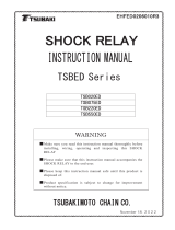
3.2 Terminal layout and internal circuit
Terminal layout Internal circuit
No. Signal name
1) b0
2) B0
3) b1
4) B1
5) b2
6) B2
7) b3
8) B3
9) 24V DC+
10) A0
11) NC
12) A1
13) NC
14) A2
15) NC
16) A3
17) NC
18) 24V DC-
Note 1) Current terminals and a voltage terminals of unused channels should be wired. By this
wiring read data becomes H7FFF.
PT100 IN EH-PT4
RTD
RTD
Internal
power
circuit
Internal current

4. Block Diagram
4-1
4. Block Diagram
4.1 Internal Block Diagram
Figure 4.1 shows the internal block diagram.
Figure 4.1 Internal Block Diagram
Note: V/F conversion refers to the conversion of voltage(V) to frequency(F).
RTD
External grounding
B0
b0
A3
B3
b3
External wiring
CPU Bus
24 V DC−
External power
24V DC
24 V DC+
EH-PT4
V/F
conversion
(Note)
Counter
Timing
control
Input conversion circuit
Constant
current
circuit
Each
part
Switch circuit
Internal
Power
Supply
circuit
A0
Line-
arize
Shielded
wire
Photocoupler insulation
RTD

5. External Wiring
5-1
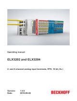
5. External Wiring
5.1 Resistance Temperature Detective Connection Method and External Wiring
Figure 5.1 External Wiring
Note 1: The external wire length shall be less than 200 m for each channel. In addition, the total
resistance of the wires of each channels to be connected to the current terminals (A0 to A3,
B0 to B3) shall be less than 400 ohm.
Note 2: Use shielded cable and connect shielded to functional earth on the both sides or one side,
which depends on the noise environment.
Note 3: The earth terminal on the power supply module and External power supply 24 VDC must be
connected to the functional earth. When functional earth area doesn't do, temperature data
sometimes become unstable. The data becomes unspecified.
b0
B0
b1
B1
b2
B2
b3
B3
+24V
A0
NC
A1
NC
A2
NC
A3
NC
-24V
External power supply
24VDC
Grounding (Note2)
External wiring(Note1)
Use a shielded cable
Make a short-circuit on
unused channel shown as
the figure.
The temperature data
becomes H7FFF.
A0 to 3 : Current terminal
B0 to 3: Current terminal
b0 to 3: Voltage terminal
RTD
RTD
RTD

6. Setting
6-1
6. Setting
6.1 Setting of temperature range
This module can be set to three temperature ranges by the dip switch shown in below.
Table 6.1 Temperature rage setting
Temperature
measurement range
Setting switch
Pt100
-20 to +40 °C
ON
OFF
Pt100
-50 to +400 °C
ON
OFF
Pt1000
-50 to +400 °C
ON
OFF
Note: Do not use the setting which is not written in the table, because the temperature data
becomes undefined.
1 2 3 4 5 6 7 8
1 2 3 4 5 6 7 8
1 2 3 4 5 6 7 8
Setting switch
(Switch 1)
1,2,5 ON
3,6 ON
4,7 ON

7. Collection of Temperature Data
7-1
7. Collection of Temperate Data
7. 1 I/O Allocation
The temperature data of each channel is collected in the CPU as the temperature conversion data
corresponding to the temperature.
(1) I/O assignment
The I/O assignment shall be set as “WX4W" by your programming software or the peripheral
equipment.
(2) I/O allocation
Depending on the module installation position, the temperature conversion data is stored in the
word input number shown below.
Figure 7.1
The setting of n is determined by the module installation position, as shown below.
Allocation address WX n
Word number (0 to 3)
Slot number (0 to 7)
Unit number (0 to 1)
Figure 7.2
WX n0
1
2
3
Channel 1 temperature
conversion data
Channel 2 temperature
conversion data
Channel 3 temperature
conversion data
Channel 4 temperature
conversion data
Slot number
EH-PT4
0 • • • • • • • • • • n
AVR CPU
Page is loading ...
Page is loading ...
Page is loading ...
Page is loading ...
Page is loading ...
Page is loading ...
Page is loading ...
Page is loading ...
Page is loading ...
Page is loading ...
Page is loading ...
Page is loading ...
Page is loading ...
Page is loading ...
Page is loading ...
/