Page is loading ...

STERILMATIC
DIGITAL ELECTRIC STERILIZER
INSTALLATION - OPERATION - MAINTENANCE
Telephone: (802) 658-6600 Fax: (802) 864-0183
www.marketforge.com PN 14-0413 Rev E (11/17)
© 2017 - Market Forge
MODELS
STM-ED
STM-EDX

Your Service Agency’s Address:
Model
Serial number
Sterilizer installed by
Installation checked by

TABLE OF CONTENTS
INSTALLATION
Introduction .............................................................. 2
Service Connections ..................................................... 4
Installation Instructions ................................................... 5
Optional Cold Water Condenser ........................................... 6
Pan Supports and Bafes ................................................. 7
Optional Stands .......................................................... 9
OPERATION
General Operating Instructions ........................................... 10
Minimum Sterilization Times ............................................. 11
Digital Control Panel .................................................... 12
Detailed Operating Instructions ........................................... 13
MAINTENANCE
Cleaning ............................................................... 18
Warranty ............................................................... 19
IMPORTANT
WARNING: Improper installa-
tion, adjustment, alternation,
service or maintenance can
cause property damage, in-
jury or death. Read the instal-
lation, operation and mainte-
nance instructions thoroughly
before installing or servicing
this equipment.
FOR YOUR SAFETY
Do not store or use gasoline or
other ammable vapors or liq-
uids in the vicinity of this or any
other appliance.
The information contained in this
manual is important for the prop-
er installation, use, and mainte-
nance of this sterilizer. Adher-
ence to these procedures and
instructions will result in satis-
factory baking results and long,
trouble free service. Please
read this manual carefully and
retain it for future reference.
ERRORS: Descriptive, typo-
graphic or pictorial errors are
subject to correction. Speci-
cations are subject to change
without notice.

2
INSTALLATION
Introduction
PRODUCT DESCRIPTION
The Market Forge Sterilmatic Sterilizer with Digital Con-
troller (model STM-ED) is a compact, automatic, low cost
steam pressure sterilizer (autoclave).
The sterilizing cylinder is a 3/16” (4.8mm) thick wall, weld-
ed aluminum. The exterior is made of polished stainless
steel. Interior dimensions of 16” (406mm) diameter and
26” (660mm) long with a cubic content of 5,220 cubic
inches (0.085 cubic meters) and has a door opening of
13-1/2” (343mm) wide and 11” (279mm) high. The steril-
izing compartment has a pan capacity of:
• (3) 12” x 20” x 2 ½” (305mm x 508mm x 64mm) or,
• (2) 12” x 20” x 4” (305mm x 508mm x 102mm) or,
• (1) 12” x 20” x 6” (305mm x 508mm x 152mm)
The sterilizer door is a self-sealing type that cannot be
opened until the steam pressure is completely exhausted
from the chamber. The door is 12 gauge stainless steel
and removable for cleaning without tools. The door gas-
ket is one-piece molded, also replaceable without tools
or cement.
The sterilizing cycle is fully automatic with the time, tem-
perature and venting controlled by the microprocessor
based, digital controller.
The sterilizing temperature can be set anywhere in a
range from 225°F (107°C) and 250°F (121°C). There is
an on-board data logger/printer. The data logger records
the time, temperature and pressure for each sterilization
cycle. This data can be stored for future printing or printed
out following each cycle.
OPERATING ENVIRONMENTAL CONDITIONS
This unit is designed for commercial use and to be safe at
least under the following conditions:
• For indoor use only.
• For use at altitudes up to 6500ft (2000m)
• For use at temperatures from 41°F (5°C) to 104°F
(40°C).
• Maximum relative humidity 80% for temperatures up
to 88°F (31°C) decreasing linearly to 50% relative
humidity at 104°F (40°C).
• Main supply voltage uctuations not to exceed ±
10% of nominal voltage.
• Transient overvoltages according to Installation Cat-
egories II (in accordance with IEC 664).
• Pollution Degree 2 (in accordance with IEC 664).
SERVICE & TECHNICAL INFORMATION CONTACT
WARNING
This unit should be serviced by qualied ser-
vice personnel only.
Your Sterilmatic Sterilizer has been developed to answer
the need for a compact, automatic, low-cost steam pres-
sure sterilizer. The following instructions cover installa-
tion. Should service be required, it is readily available by
contacting our authorized service agency located nearest
to you. The name of your local service company can be
obtained on our website, www.mi.com.
INTENDED USE - STERILIZATION CYCLE
This unit is intended to be operated intermittently. After
a pre-heat cycle, the longest period of sterilization (heat-
ing) should be a maximum of 60 minutes. The digital tim-
er allows up to 99 minutes, but it should be kept at no
more than 60 minutes. After each use the unit should be
opened for removal and reloading of product. The water
level should be checked after each use and relled when
necessary.
WATER CONDITIONS
When sterilizing culture mediums that generate sul-
de gas or chlorine gas, the inside of the chamber
must be cleaned and rinsed thoroughly without fail
Market Forge from time to time is asked the question
about using distilled or deionized water for use with our
Sterilizer models STM-ED and STM-EDX. We are always
asked why these water choices are not allowed for use
with our units and what would be recommended. To ad-
dress this situation, we have complied the following as a
means of satisfying these questions:
1. We have found that the use of distilled or deionized
water will aggressively attack the pure coat of Alumi-
num Alclad, which protects the bottom surface from
oxidizing and then eventually pitting (reference: Op-
erating and Maintenance Instructions).
2. In addition pitting can also be caused by several other
external environmental factors. Few examples are as
follows. These conditions have been highlighted in
our documentation.
• Grains of hardness in the water supply should
be as follows (.25 to 2).
• A pH imbalance in the water supply can greatly
affect the life to the aluminum cylinder. The pH
range that would be recommended is between
7.0-8.5.

3
INSTALLATION
• The lack of a positive electrical ground can
cause an electrolytic reaction that will accelerate
pitting.
• Another contribution to accelerate pitting is the
type of cleaning solutions used or the abrasive
scrubbing pads. If a low pH is present with the
detergents being used or an abrasive pad, the
protective Alclad coating will be removed during
the cleaning process.
• Spillage of media being sterilized can also con-
tribute to the accelerated pitting if it is corrosive.
• CHLORINE LEVEL ≤ 1 PPM.
IMPORTANT
Market Forge will not be responsible for dam-
age resulting from the use of hard or corrosive
water, from failure to drain the unit daily, or
from inadequate cleaning procedures.
Introduction

4
INSTALLATION
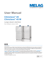
Service Connections
Figure 1
ELECTRICAL SPECIFICATIONS
Domestic
Model
kW Hz
1 Phase
3 Phase
208V 240V 208V 240V
STM-ED
9.3 60 45A - 26A -
12.4 60 - 52A - 30A
Export
Model
kW Hz
1 Phase
3 Phase
220V 240V 220/380V 240/415V
STM-EDX
10.4 50 48A - 16A -
12.4 50 - 52A - 18A
Unit must be grounded. Main supply voltage fluctuations are not to
exceel ± 10% nominal supply voltage.
WATER SUPPLY
Good quality water feed is the responsibility of the owner. Water qual-
ity must be within the following general guidelines.
TDS: 40-125 ppm Hardness: 35-100 ppm Chlorine: <0.2 ppm
Silica: <13 ppm Chlorides: <25 ppm
Chloramine: <0.2 ppm pH: 7.0 - 8.5
The best defense against poor water quality is a water treatment
system designed to meet your water quality conditions.
Appliance to be installed with backflow protection according to fed-
eral, state or local codes.
DIMENSIONS ARE IN INCHES [MM]
D
CONDUIT
15.5
[394]
3.5
[89]
C
A
9.34 [237]
18.69 [475]
B
SEE
NOTE 2
4.75
[121]
B1
25 [635]
1.5 [38]
30 [762]
SEE NOTE 2
B
6 [152]
B1
A
4 [102]
ADJ. LEGS
Customer provided Drain Catch Pan
Approx. 4-6 quarts (3.8-5.7 liters)
STEAM SHIELD
3 [76]
5.63
[143]
23 [584]
1 [25]
C
21 [533] CHAMBER
9 [230]
12 [305]
DOOR IN
OPEN POSITION
9 [228]
CLEARANCE
11 [280]
CLEARANCE
C
D
CONDUIT
3 [76]
Locate electric box as close to
sterilizer as possible and per
local electrical codes
STEAM SHIELD
SERVICE CONNECTIONS
A Drain - 1/2” (13mm) N.P.T. of 3/8” (10mm) OD copper
(see note 1)
B Steam Exhaust Connection - 5/8” (16mm) (see note 2)
C Electrical Connection - (*see electrical specifications
table)
D Power Supply
NOTES:
1. An air break must be provided if a unit drain line is run.
2. Vent exhaust to atmosphere. B1 is actual connection, but
must exit casing at B.
3. Heat of Rejection ( Heat Loss Into the Room) 6,000
BTU’S.
IMPORTANT: Exhaust line must be vented to the outside to elimi-
nate the exhaust steam and the accompanying noise from enter-
ing the room. Use 1/2” (13mm) copper tubing or suitable alternate.
The overall height and length of the line should not rise more then
4’ (1.2 meters) above the unit and exceed 15’ (4.5 meters) with a
minimum of bends. The line should slope downward after leaving
the sterilizer in order to ensure condensate drainage.
IMPORTANT: Failure to comply with this outline will affect the
sterilization process.
When an exhaust condenser is supplied; the following services
must be provided: 1/2” (13mm) cold water: 1” (25mm) waste: 115V
electrical line.

5
INSTALLATION
Installation Instructions
INSTALLATION
Set sterilizer on counter, using the 6” (152mm) legs pro-
vided or assemble the optional stainless steel stand with
under-shelf. If your Sterilmatic includes a water-cooled
exhaust condenser, we recommend the use of the Steril-
matic stand, part number 95-6060. First, level unit in
place, then adjust rear legs to pitch the unit forward 1/4”
(6mm) to insure positive drainage of the cylinder.
ELECTRICAL
Connect to proper electrical supply box and disconnect
switch as shown on one of the following schematic dia-
grams - 208 or 240 volts, single or three phase. Connec-
tion is made from the rear of the unit, through the conduit
to the terminal box located at the front of the unit.
Electric supply connection for STM-ED
Connect to proper electrical supply as indicated on name-
plate on top of unit. The power supply cord is brought in
from the rear of the unit, through the conduit and the con-
nection is made at the terminal box located at the front of
the unit.
Electric supply connection for STM-EDX (export mod-
els)
Connect to proper electrical supply as indicated on name-
plate on top of unit. Connection is made from the rear of
the unit, through the conduit to the terminal box located at
the front of the unit. All control circuits are 220 volts.
In order to accomplish this, a current-carrying grounded
neutral must be provided.
Thus, a three phase system must be 4-wires. Most elec-
trical codes require, and we recommend, that a separate
switch be located within sight of the sterilizer.
OUTSIDE VENTING
Connect 1/2” (13mm) nominal tubing exhaust to outside
vent connection located on top of unit, within the control
housing.
IMPORTANT: Exhaust line must be vented to the out-
side to eliminate the exhausted steam and the accom-
panying noise from entering the room.
Use 1/2” (13mm) copper tubing or suitable alternate. The
overall height and length of the line should not rise more
then 4 feet (1.2 meters) above the unit and exceed 15 feet
(4.5 meters) with a minimum of bends. The line should
slope downward after leaving the sterilizer in order to in-
sure condensate drainage.
WATER-COOLED EXHAUST CONDENSER
If outside venting is not possible, an optional water-cooled
condenser is available for connection to an open drain. If
required order part no. 95-0436 kit.
TRAY SUPPORTS
Install side tray supports. Tray supports are attached by
means of key-hole clearance slots which are slipped over
studs located on the sides of the Sterilmatic chamber.
BAFFLE INSTALLATION
To insure maximum drying of packs, a bafe is supplied
with your Sterilmatic. Place perforated splash bafe in
bottom of the sterilizing chamber. Install small bafe with
no perforation at the rear of the upper tray support chan-
nel.
NOTE: The perforated bafe is not to be used as a shelf
to place media or other items. It is intended to
eliminate splashing.
OPERATION CHECK
To check for proper operation of unit:
1. Close drain valve by turning handle clockwise.
WARNING
DO NOT OPEN DRAIN VALVE WHILE UNIT
IS OPERATING. PREMATURE OPENING MAY
RESULT IN SCALDING OF OPERATOR.
2. Fill chamber with 4 to 5 quarts (3.8 to 4.7 liters) of
ordinary tap water. DO NOT USE DISTILLED OR DE-
IONIZED WATER.
3. Close chamber door.
4. Set exhaust selector to INSTRUMENTS AND PACKS
(fast exhaust) or LIQUIDS (slow exhaust).
5. Set timer to 15 minutes. Cycle will go to completion
automatically.

6
INSTALLATION
Item Part No. Description Qty
1 95-2119 Steam condensing unit 1
2 95-2219 Thermostat Box Assy. 1
3 95-0086 Exhaust line 1
5 15-7057 Copper tubing 3/8 OD 22.25”
6 10-1775
Rd. Hd. Mach. Screw,
1/4-20
2
7 10-2500 Lockwasher, 1/4 2
8 10-2308 Hex Nut, 1/4-20 2
9 10-1812
Rd. Hd. Mach. Screw, 10-
32
2
10 10-2505 Lockwasher, 10 2
11 10-2340 Hex Nut, 10-32 2
12 95-4009 Front Template (7” Lg)
1
13 95-4010 Back Template (11” Lg) 1
SERVICE CONNECTIONS REQUIRED
A 1/2” IPS Cold Water Connection
B 1” IPS Drain Connection (See Note 3)
C 115V Elec. Connection 7/8 Ø knockout (cond. unit)
D Electrical Connection
Figure 2
Optional Cold Water Condenser
Figure 3

7
INSTALLATION
Pan Supports and Bafes
1. Locate the mounting studs on the inside of the cham-
ber. There are two rack mounting studs on each side.
Mounting Studs
Figure 4
2. Taking one pan support and positioning rack so that
the pan stop is facing the rear of the unit and the
wires are facing toward the center of the unit. The
pan stop is a piece of sheet metal welded to the rack
with a 65° bend.
3. Begin to hang the pan support by placing the rear
key-way slot onto the rear mounting stud and slide
the rack until the slot sits on the mounting stud. When
this is done correctly the front mounting stud will be in
position to place the front key-way slot. Slide the rack
down into its correct position.
Keyway Slot
Pan Stop
Figure 5
4. After installing one pan support rack correctly, you
can install the upper bafe. Position the bafe so that
the 45° bend is facing up towards the front of the unit
(see “Figure 6”). Slide the mounting tab onto the at
bend on the pan stop bracket. The bafe should now
stay in place by itself, but in a tilted state (see “Figure
7”).
Baffle
Figure 6
Figure 7

8
INSTALLATION
Pan Supports and Bafes
5. Position the second pan support rack into the cavity
and slide the other mounting tab onto the rack at
bend while the pan support rack is not on the mount-
ing studs. Hang the pan support by placing the rear
key-way slot onto the rear mounting stud and slide
the rack until the slot sits on the mounting stud. When
this is done correctly the front mounting stud will be in
position to place the front key-way slot. Slide the rack
down into its correct position.
6. Place the Perforated Water Bafe so that it sits on the
bottom of the inside of the sterilizer chamber.
Perforated Water Baffle
Figure 8
CAUTION
Do not cover the holes in the Perforated Water
Bafe by using it as a shelf. This will result in
a disrupted ow of steam.

9
INSTALLATION
Optional Stands
STERILMATIC OPEN STAND:
Market Forge Sterilmatic Stand can be supplemented
with an Optional Stand for utility use where maximum
compactness is desired.
The sturdy, stainless steel unit is equipped with adjust-
able leg extensions which allow the unit to be installed
and leveled over existing contours in the oor.
The open design lends itself to maximum sanitary condi-
tions because of the ease with which periodic cleaning
can be done.
Though simple in design and appearance, the sterilmatic
stand is the ideal arrangement for mounting in that it al-
lows secondary air to circulate.
STERILMATIC OPEN STAND WITH CONDENSER
Market Forge can provide the open stand with an optional
steam condenser system for use where steam exhaustion
into the room is undesirable.
The condenser is automatically controlled by the ther-
mostat. The normal factory thermostat setting is 130°F
(54°C). The open under-shelf of the stand gives added
utility providing a handy tabouret for utensils and access
for drainage of water from the sterilizing chamber.
Part No. 50 Hz Description
10-4653 10-4653 Thermostat
10-4035 10-7074 3/8” Solenoid
10-5731 10-5731 1/2” Water Stop Valve
95-2106 95-2106 Water Injection Assy.
95-1680 95-1680 Shelf

10
OPERATION
General Operating Instructions
IMPORTANT
Make sure the drain valve is closed. Fill bot-
tom of the sterilizer chamber with approxi-
mately six quarts of water or just below ledge
at bottom of door opening. (If water supply
is known to be hard or corrosive, a source of
treated water should be used.) DO NOT USE
DISTILLED OR deionized WATER.
1. LOAD STERILIZER: Use proper sterilizer loading
procedures when placing materials in sterilizer cham-
ber. All solid containers or instruments must be placed
so that water or air will not be trapped in them.
2. CLOSE DOOR: Grasp handle, and holding it in verti-
cal position, pull door down until bottom of door rests
in the bottom of door opening. Then rotate handle for-
ward, engaging the lower curved portion under the
horizontal rod in the casting at the bottom of the door
opening. Push handle all the way down and back until
door is locked securely in position.
3. DETERMINE CORRECT STERILIZATION TIMES:
Refer to the table on the following page for minimum
sterilization times table.
NOTE: In no case should the timer be set to less
than 15 minutes. Sterilization will not be ac-
complished in less than 15 minutes exposure
time.
4. When the sterilizer chamber reaches the selected
temperature, the timed Heating/Sterilization cycle will
begin. When the Heating/Sterilization cycle is com-
pleted, the electric supply to the heating elements will
be opened (shut off) automatically. When the chamber
pressure reaches 0 (zero) the door may be opened.
NOTE: Before opening the chamber door be sure
to have the Control Panel Flip Cover in the
‘DOWN’ position. This protects the LCD
screen from coming into contact with too
much steam. At this point you may release
the handle and let go to avoid possible con-
tact with the remaining escaping steam.
When opening the door allow a few seconds
for steam to escape from the chamber before
opening completely.
NOTE: For more detailed Operating Instructions
please refer to “Detailed Operating Instruc-
tions” on page 13.
5. To assist in drying racks, release door handle after
pressure has been attained at start of cycle. Pres-
sure in chamber will keep door closed. The use of a
wire basket will provide better drying for dressings.
At end of sterilizing cycle, release door handle and
open slightly. Do not lift door to open position. This
will allow steam and moisture to escape. Allow door
to remain in this position for 15 to 20 minutes before
removing load. Small packs can be dried successfully
with this procedure. We do not recommend the ster-
ilization of large packs, such as linens. Be sure con-
densate bafes are in position in the chamber.
6. Remove load and check water level for next opera-
tion.
STERILIZATION GUIDE
• PACKS (Linens, gloves, etc.): Use wire basket
to facilitate drying. Be sure condensate bafes are
in place. Place packs on edge and arrange load in
chamber, so that only minimal resistant to passage
of steam through the load will exist.
NOTE: Place gloves in upper two-thirds of chamber.
• JARS, CANISTERS (etc.): Place containers on side
to allow for displacement of air and complete contact
of steam to surfaces. Drying is also facilitated.
• PETRI DISHES, PIPETTES, DESICCATORS (etc.):
Should be inverted.
• UTENSILS, TREATMENT TRAYS: Placed on edges
to facilitate drying.
• INSTRUMENT SETS: Place instruments set in trays
having mesh or perforated bottoms. Place trays at
on shelves.
• COMBINING FABRICS & HARD GOODS: Place
hard goods on lowest shelves.
• PLASTIC UTENSILS: DO NOT stack or nest plastic
items.
• LIQUIDS: Sterilize liquids separately from other sup-
plies or materials. Set vent to slow.
• SMALL ITEMS: Sterilize small items in baskets, or
trays.
IMPORTANT
IF THE EQUIPMENT IS USED IN A MANNER
NOT SPECIFIED BY THE MANUFACTURER,
THE PROTECTION PROVIDED BY THE EQUIP-
MENT MAY BE IMPAIRED.

11
OPERATION
Minimum Sterilization Times
TIME (Minutes) ARTICLES
15 • Glassware, empty, inverted.
• Instruments, metal in covered or open tray, padded or unpadded.
• Needles, unwrapped.
• Pipettes, blood diluting, serological, volumetric, etc
• Tubing glass (6mm), (10mm) inverted
20 • Flasked solutions 75-250 ml.
• Instruments, metal combined with other materials in covered and/or padded tray.
• Instruments wrapped in double thickness muslin.
• Rubber gloves, catheters, drains, tubing, etc. Unwrapped or wrapped in muslin or paper.
30 • Brushes in dispensers, in cans of individually wrapped.
• Dressings, wrapped in paper or muslin, small packs only.
• Flasked solutions 500-1000 ml.
• Syringes, unassembled, individually packaged in muslin or paper.
• Needles, luer, individually packaged in glass tubes or paper.
45 • Flasked solutions 1500-2000 ml.

12
OPERATION
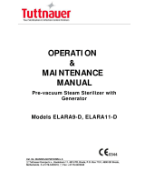
Digital Control Panel
Before operating this unit be sure to have read the Own-
er’s manual for proper setup, service connections and
installation. In addition, the Owner’s manual will cover
sterilization recommendations, daily cleaning procedures
and parts lists.
ITEM DESCRIPTION
1 Control Panel Power - ON ( I ), OFF ( 0 )
2 Reset Button
3 Low Water Indicator Light
4 Down Key
5 Printer Key
6 Preset Keys
7 Up Key
8 Start / Cancel Key
9 Digital LCD Display
10 Temperature Key
11 Time Key
12 Vent Key
13 Print out
14 Printer Door Button
The Digital Controller is made up of the Operational Keys,
Digital LCD Display and the Data Logger/Printer. The op-
erator can set the controller to display in either degrees
Fahrenheit (°F) with pressure in PSI or in degrees Celcius
(°C ) with pressure in kPa.
During operation the Digital LCD Display will show the
actual temperature within the sterilizer chamber, the time
remaining for the sterilizer cycle and the vessel pressure
in digital form and bar form. It will also display the current
cycle state, Heating up, Timing (sterilizing) or Venting.
The three operating parameters that can be set by the
operator are sterilizing Temperature, sterilizing Time and
Venting mode.
The sterilizing temperature can be set in a range from
225°F (107°C) to 250°F (121°C).
The sterilizing Time can be set in Minutes and Seconds
(if desired).
The Venting mode can be set to FAST (approximately 3
minutes) or SLOW (approximately 11 minutes).
To initiate a sterilizing cycle you need to set three param-
eters, Temp, Time and Venting. Or you can set commonly
used values for these parameters into three ‘Preset’ keys.
Each Preset key can store a value for all three param-
eters. The parameter values stored in the Preset keys
can easily be selected before running a sterilization cycle.
This avoids you having to set all three parameters every
time you run the unit.
Each sterilization cycle records the temperature, time and
pressure at one minute intervals during the heat-up cycle,
the sterilization cycle and the venting cycle. These cycles
are described in more detail below. The recorded data
can be printed out after each complete run or printed out
later, on an as-needed basis.
2
11
10 9
7 8
13
1 3 12
4 5 6
14
Figure 9

13
OPERATION
Detailed Operating Instructions
SETUP
Make sure unit is connected to its electrical source. Make
sure unit has recommended amount of water in its cham-
ber. Make sure unit drain is closed. If a ventilation hood
is required, make sure unit is placed accordingly under
the hood.
Be sure that the unit’s door is closed and locked before
operating!
Once the unit has power, push the black Control Panel
Power switch to On ( I ). This will bring power to the con-
trol panel and illuminate the Digital LCD Display screen.
You are now ready to use the unit.
MANUAL PROGRAMMING
The rst step is to decide what form of temperature and
pressure measurement you want to use, Fahrenheit and
PSI or Celsius and kPa. This can be changed at any point
during operation.
Setting units (°F & PSI) or (°C & kPa);
1. Press and hold the UP key and the DOWN key while
simultaneously pressing and releasing the TEMP key
will toggle between (°F/PSI) and (°C/kPa).
Setting Temperature
1. While the unit is powered up but not in use, consid-
ered the ‘Idle State’, the temperature being displayed
is the current temperature within the sterilizer cham-
ber.
2. Pressing and releasing the TEMP key will display the
current set-point temperature for three seconds.
3. To set the target sterilization temperature set-point;
a. Press and hold the TEMP key until the display
goes blank and shows only the temperature.
Now press the appropriate UP or DOWN key to
get to desired set-point.
b. When the full display returns the target set-point
has been set.
Setting Time
1. While in the ‘Idle State’ the Time being displayed is
the current time set-point.
2. To set the target sterilization time set-point;
a. Press and hold the TIME key until the display
goes blank except for the minutes. Now press
the appropriate UP or DOWN key to reach the
desired sterilization set-time minutes.
b. After three seconds the minutes will blank and
the seconds set-point will be displayed. If you
need to set the desired seconds, again, use the
appropriate UP or DOWN keys.
c. If seconds are not required than either don’t
touch any key and after three seconds the full
display will come back and the TIME is now set or
immediately press the TIME key again and that
will also set the time.
Setting VENT mode
1. While in the ‘Idle State’ the VENT mode will be dis-
played as either FAST or SLOW, whichever is active.
2. To set the desired VENT mode (SLOW or FAST);
a. At any point during any cycle the VENT mode
can be toggled simply by pressing and releasing
the VENT key.
Starting the unit
1. Once you have set your desired TEMP, TIME and
VENT type you can now proceed in starting the unit.
2. To start unit;
a. Press the START/CANCEL key
Stopping the unit
1. Once the unit is started it will run through all 3 cycles
automatically (cycles are described below) and nish
in the DONE state (also described below).
2. If at any time throughout the cycle you have to stop or
cancel the cycle just press and hold (for 3 seconds)
the START/CANCEL key.
3. After stopping the unit in this manner the unit will still
have to go through the VENT cycle to release the
pressure within the chamber before you can open the
unit door.

14
OPERATION
Detailed Operating Instructions
Description of cycles
1. HEATING cycle – Once the START/CANCEL key is
pressed the unit will ash the HEATING icon while the
sterilizer is heating up to the sterilization temperature
set-point. While it is heating the set-point TIME is dis-
played and will not change.
2. TIMING (sterilizing) cycle – When the unit reaches its
set-point temperature the unit will enter the steriliza-
tion or TIMING cycle. At this point the unit will display
and count down the sterilization time.
3. VENTING cycle – When the timing (sterilization) cy-
cle time reaches zero the set VENTING cycle begins.
The FAST VENT is programmed to vent for 3 minutes
through the solenoid valve. The SLOW VENT is pro-
grammed to vent for 11 minutes through a bleeder
orice.
a. DONE state – At the completion of the VENTING
cycle the unit will display DONE and a beeper
will sound. The beeper sequence will be ON for
1 second and OFF for 9 seconds. This sequence
will repeat until any key on the control panel is
pressed or 3 minutes have passed.
b. Once in the DONE state it is safe to open the
chamber door. Before opening the chamber door
be sure to have the Control Panel Flip Cover in
the ‘Down’ position. This protects the LCD screen
from coming into contact with too much escaping
steam from the chamber. When the door is left in
the closed position you may notice a rise in the
temperature and pressure on the LCD screen.
You should open the chamber door to allow the
chamber to cool.
NOTE: There is never any harm in releasing the
chamber door latch. If there is pressure in-
side the chamber the door cannot open due
to its design which does not allow the door to
open under pressure.
PRESET KEYS
There are three PRESET keys numbered 1, 2 & 3. In each
key you can save set-point values for the Temperature,
Time and Vent mode. For example, if you commonly need
to sterilize a media that requires specic set-point values,
you can save these specic values into a PRESET key.
This way you don’t need to keep setting the Temp, Time
and Venting info before each running of a sterilization
cycle.
Programming PRESET Keys
To save values into a PRESET key;
1. Press and hold the desired PRESET key (1, 2 or 3).
The display shows the values currently stored in that
preset key. When the “PRESET” icon and the preset
“number” icon in the display start to ash, the values
are now ready to re-program. At this point you can
change any or all of the parameters, Temp, Time,
Vent as described previously.
2. Every three seconds without an UP or DOWN key
press the display will proceed from TEMP, MINUTES,
then to SECONDS waiting for new preset set-points
then exits the program preset state.
3. During this programming state you can advance from
the Temp menu to the Time menu simply by pressing
the TIME key.
4. Likewise, while in the Time menu you can advance
from Time-minutes to Time-seconds simply by press-
ing the TIME key.
5. In addition, while in the Time menu you can go back
to the Temp menu by pressing the TEMP key.
6. At any point during this programming state you can
press the appropriate PRESET number key and that
will store the new values and exit the programming
state.
Using PRESET Keys
1. While the unit is in the ‘Idle State’ simply press the
appropriate PRESET key (1, 2 or 3) to use the values
previously stored into that PRESET key. At this point
you just need to press the START/CANCEL key.

15
OPERATION
Detailed Operating Instructions
Figure 10
Printing/Data Logger
This unit is set up to record the Time, Temperature and
Pressure during all phases of the full sterilization cycle.
All three of these parameters are recorded at one-minute
intervals. The data logging clearly labels the printed out-
put with headers separating the three cycles, HEATING,
STERILIZING and VENTING.
Each run is assigned a unique ID number that is printed at
the top of the printout.
Each unique ID number is made up of two numbers sepa-
rated by a dash (-). (Example; #237-00053)
The rst 3 digit number is a number that never changes. It
is a unique number that identies the sterilizer unit itself.
The last ve digits are incremented by one for every time
the unit is run.
Also included at the end of each printout is the following;
DATE:
OPERATOR:
COMMENTS:
The DATE, OPERATOR and COMMENTS elds can be
hand written in if required.
PRINT Key
In the LCD Display, if the word PRINT is displayed then
the recorded data will be automatically printed at the end
of the full sterilization cycle. Likewise, if the word PRINT
is not displayed then the recorded data will not be printed
automatically after the full sterilization cycle completes.
1. To toggle between PRINT enable and PRINT disable
just press and release the PRINT key. This can be
performed at any time during the Heating, Timing
(Sterilization) or Venting cycles.
Printing previously run cycles
The data logger will store approximately 20 full steriliza-
tion cycles. This number may vary slightly depending on
how long each cycle runs. For example, the data logger
can store more cycles set at 30 minutes versus cycles all
set at 60 minutes.
As stated before each full cycle is assigned a unique ID
number. This number can be used to scroll back through
the data logger and print out the exact cycle you want to
print out. There is also an option to print out ALL the previ-
ous cycles.
To print out selected cycles;
1. Press and hold the PRINT key. The display will show
the ID of the last run cycle. To scroll back through
the cycles just press the DOWN key. Likewise, during

16
OPERATION
Detailed Operating Instructions
the scrolling, you can hit the UP key to scroll forward
through the cycles. At your selected cycle ID number
just press and release the PRINT key.
To print out all the cycles;
1. Press and hold the PRINT key. When the display
shows the last run ID number keep hitting the DOWN
key until the word ‘ALL’ is displayed. Now press and
release the PRINT key.
Printer Paper cutting
The paper will be cut automatically at the end of each
single print or printing ALL.
Printer Paper Changing
Follow these steps to re-load the printing paper;
1. Push the printer door “open” button. Two doors will
open, the inner door and outer door.
2. Remove paper roll spool from printer. Remove black
plastic spindle from center of spent paper roll. DO
NOT DISCARD BLACK PLASTIC SPINDLE!
3. Insert black plastic spindle into new paper roll. Insert
new paper roll into printer. (Note: paper exits from
top of roll)
4. Hold paper tip with one hand and close the inner door
by pressing on the yellow strip.
5. Close black outer door making sure that paper pro-
trudes through the slot.
Figure 11

17
OPERATION
Detailed Operating Instructions
Low Water Reset
If the water inside the chamber is allowed to run dry it will
trigger the Low Water Cut-off. At this point the unit will;
• Shut down all three heating elements
• Light the red Low Water indicator light.
• Start the Venting cycle
• The Data Logger will record the error code
Note The sterilizer’s LCD display may show the
temperature and pressure rising slightly dur-
ing this venting period but that is normal.)
• Once the unit completes the VENTING cycle the
screen will ash ‘DONE’ and display ‘SERVICE’ and
the Beeper will sound.
Steps to Reset the unit
1. The LCD display now shows ‘ERR 06’ and beeper
changes to a constant tone.
Note: An explanation of Error Codes is shown be-
low in the Appendix
Recommended steps but not required:
1. Shut off ‘ON/OFF’ power switch to controller.
2. Wait until unit cools down. Opening the unit door will
help the unit to cool down quicker.
3. When power is restored the buzzer tone will continue
and ‘ERR 06’ will be displayed again.
4. Open the door and add water to the chamber.
5. Once the chamber has cooled enough you can press
the Low Water Cutoff RESET button. Listen for the
‘click’ sound.
If constant tone continues press any menu key to turn
off.
6. The unit is now back in the ‘Idle State’ and ready to
be run again.

18
MAINTENANCE
Cleaning
DAILY CLEANING PROCEDURE (AT THE END OF
EACH DAY):
When sterilizing culture mediums that generate sul-
de gas or chlorine gas, the inside of the chamber
must be cleaned and rinsed thoroughly without fail.
1. Remove bottom splash bafe.
IMPORTANT
STERILIZING CHAMBER MUST BE CLEANED
AND DRAINED DAILY USING THE FOLLOW-
ING PROCEDURE. WASH WETTED PORTION
OF THE CYLINDER THOROUGHLY BY ADDING
A MILD DETERGENT TO WATER IN CYLIN-
DER.
2. If a soft cloth or brush is used with the detergent and
does not completely remove the surface lm, a nylon
soap pad should be used. After washing thoroughly
rinse with clean water. Dry cylinder* and leave door
open overnight.
* The Sterilmatic cylinder is constructed of corrosion re-
sistant Alclad aluminum alloy. The protective properties of
this material afforded to the interior portion of the cylinder
which is exposed to water may be destroyed by allowing
a lm to form. Such a lm can be caused by salts or other
contaminants in the water. Corrosion may also occur if
water is not drained daily.
WEEKLY CLEANING
In addition to the daily cleaning it is necessary to clean
the air intakes on a weekly basis. Air intakes provide nec-
essary cooling air to the internal components. They are
generally located on the rear and sides of the equipment.
/