Page is loading ...

Subject to change without prior notice info@acs.com.hk
www.acs.com.hk
Application Programming Interface V1.09
ACR1252U
NFC Forum Certified
Reader

ACR1252U – Application Programming Interface info@acs.com.hk
Version 1.09
www.acs.com.hk
Page 2 of 80
Table of Contents
1.0. Introduction ............................................................................................................. 4
2.0. Features ................................................................................................................... 5
3.0. Acronyms and Abbreviations ................................................................................. 6
4.0. Architecture ............................................................................................................. 7
5.0. Host Programming (PC-linked) API ........................................................................ 8
5.1. PCSC API .............................................................................................................................. 8
5.1.1. SCardEstablishContext ................................................................................................. 8
5.1.2. SCardListReaders ......................................................................................................... 8
5.1.3. SCardConnect ............................................................................................................... 8
5.1.4. SCardControl ................................................................................................................ 8
5.1.5. ScardTransmit ............................................................................................................... 8
5.1.6. ScardDisconnect ........................................................................................................... 8
5.1.7. APDU Flow .................................................................................................................... 9
5.1.8. Escape Command Flow .............................................................................................. 10
5.2. Contactless Smart Card Protocol ........................................................................................ 11
5.2.1. ATR Generation .......................................................................................................... 11
5.3. Pseudo APDU for Contactless Interface ............................................................................. 14
5.3.1. Get Data ...................................................................................................................... 14
5.4. APDU commands for PCSC 2.0 Part 3 (version 2.02 or above) ......................................... 15
5.4.1. Command and Response APDU Format .................................................................... 15
5.4.2. Manage Session Command ........................................................................................ 17
5.4.3. Transparent Exchange Command .............................................................................. 21
5.4.4. Switch Protocol Command .......................................................................................... 25
5.4.5. PCSC 2.0 Part 3 Example .......................................................................................... 26
5.5. PICC Commands for MIFARE® Classic (1K/4K) Memory Cards........................................ 29
5.5.1. Load Authentication Keys ........................................................................................... 29
5.5.2. Authentication for MIFARE® Classic (1K/4K) ............................................................. 30
5.5.3. Read Binary Blocks ..................................................................................................... 33
5.5.4. Update Binary Blocks .................................................................................................. 34
5.5.5. Value Block Operation (INC, DEC, STORE) .............................................................. 35
5.5.6. Read Value Block ........................................................................................................ 36
5.5.7. Copy Value Block ........................................................................................................ 37
5.6. Accessing PCSC-compliant tags (ISO 14443-4) ................................................................. 38
5.7. Accessing FeliCa tags ......................................................................................................... 40
5.8. Peripherals Control .............................................................................................................. 41
5.8.1. Get Firmware Version ................................................................................................. 41
5.8.2. LED Control ................................................................................................................. 42
5.8.3. LED Status .................................................................................................................. 43
5.8.4. Buzzer Control ............................................................................................................ 44
5.8.5. Buzzer Status .............................................................................................................. 45
5.8.6. Set LED and Buzzer Status Indicator Behavior for PICC Interface ............................ 46
5.8.7. Read LED and Buzzer Status Indicator Behavior for PICC Interface ......................... 47
5.8.8. Set Automatic PICC Polling ........................................................................................ 48
5.8.9. Read Automatic PICC Polling ..................................................................................... 50
5.8.10. Set PICC Operating Parameter .................................................................................. 51
5.8.11. Read PICC Operating Parameter ............................................................................... 52
5.8.12. Set Auto PPS .............................................................................................................. 53
5.8.13. Read Auto PPS ........................................................................................................... 54
5.8.14. Set Serial Number ....................................................................................................... 55
5.8.15. Set and lock Serial Number ........................................................................................ 56
5.8.16. Read Serial Number.................................................................................................... 57
5.8.17. Unlock Serial Number ................................................................................................. 58
5.9. NFC Peer-to-Peer Mode-related Commands ...................................................................... 59
5.9.1. Initiator Mode-related Commands ............................................................................... 59
5.9.2. Target Mode-related Commands ................................................................................ 63

ACR1252U – Application Programming Interface info@acs.com.hk
Version 1.09
www.acs.com.hk
Page 3 of 80
5.10. NFC Card Emulation Mode-related Commands .................................................................. 69
5.10.1. Enter Card Emulation Mode ........................................................................................ 69
5.10.2. Read Card Emulation Data (MIFARE® Ultralight® or FeliCa) .................................... 71
5.10.3. Write Card Emulation Data (MIFARE® Ultralight® or FeliCa) .................................... 72
5.10.4. Set Card Emulation of MIFARE® Ultralight® UID ...................................................... 72
5.10.5. Set Card Emulation FeliCa IDm .................................................................................. 73
5.10.6. Set Card Emulation Lock Data in NFC ....................................................................... 73
5.11. ACR122U Compatible Commands ...................................................................................... 74
5.11.1. Bi-color LED and Buzzer Control ................................................................................ 74
5.11.2. Get Firmware Version ................................................................................................. 76
5.11.3. Get the PICC Operating Parameter ............................................................................ 77
5.11.4. Set the PICC Operating Parameter ............................................................................ 78
Appendix A. SNEP Message .......................................................................................... 79
Appendix B. Escape Command Example ..................................................................... 80
List of Figures
Figure 1 : ACR1252U Architecture ......................................................................................................... 7
Figure 2 : ACR1252U APDU Flow ......................................................................................................... 9
Figure 3 : ACR1252U Escape Command Flow.................................................................................... 10
Figure 4 : Peer-to-Peer Flow for Initiator Mode .................................................................................... 59
Figure 5 : Peer-to-Peer Flow for Target Mode ..................................................................................... 63
List of Tables
Table 1 : Acronyms and Abbreviations ................................................................................................... 6
Table 2 : MIFARE® Classic 1K Memory Map ...................................................................................... 31
Table 3 : MIFARE® Classic 4K Memory Map ...................................................................................... 31
Table 4 : MIFARE® Ultralight® Memory Map ...................................................................................... 32
Table 5 : MIFARE® Ultralight® Memory Map (52 bytes) ..................................................................... 70
Table 6 : FeliCa Memory Map (160 bytes) ........................................................................................... 71

ACR1252U – Application Programming Interface info@acs.com.hk
Version 1.09
www.acs.com.hk
Page 4 of 80
1.0. Introduction
The ACR1252U NFC Forum Certified reader is a USB PC-linked contactless card reader/writer with a
SAM (Secure Access Module) slot, which can be used together with a SAM card for high level
security in contactless transactions. It is an NFC card reader/writer, and capable to support card
emulation and peer-to-peer communication modes. The ACR1252U reader is also NFC library
compliant to support Bluetooth and Wi-Fi NFC pairing/log-in.
ACR1252U is compliant to ISO 14443 Parts 1 to 4 supporting contactless card, MIFARE® cards,
FeliCa cards and ISO 18092 NFC tags.
ACR1252U has two reader interfaces, namely the PICC and SAM interface. Both interfaces follow the
PC/SC specifications. This API document will discuss in detail how the PC/SC APDU commands were
implemented for the contactless interface and device peripherals of ACR1252U.

ACR1252U – Application Programming Interface info@acs.com.hk
Version 1.09
www.acs.com.hk
Page 5 of 80
2.0. Features
• USB 2.0 Full Speed (12 Mbps)
• Microsoft® CCID Compliant for both SAM and PICC interface
• Smart Card Reader:
o Read/Write speed of up to 424 Kbps
o Built-in antenna for contactless tag access, with card reading distance of up to 50 mm
(depending on tag type)
o Support for ISO 14443 Part 4 Type A and B Cards, MIFARE® Classic, MIFARE® Mini,
MIFARE® Ultralight®, FeliCa, Topaz, and all four types of NFC (ISO/IEC 18092 tags)
o Built-in anti-collision feature (only one tag is accessed at a time)
o NFC Support
Card reader/writer mode
Peer-to-Peer mode
Card emulation mode
o ISO 7816-compliant SAM slot (Class A)
• Application Programming Interface:
o Supports PC/SC
o Supports CT-API (through wrapper on top of PC/SC)
• Built-in peripherals
o User-controllable bi-color LED
o User-controllable buzzer
• USB Firmware Upgradability
• Supports Android
™
3.1 and later
• Compliant with the following standards:
o ISO 18092 (NFCIP-1)
o ISO 14443 Parts 1-4
o ISO 7816 Class A (for SAM slot)
o NFC Forum
o FeliCa Performance Certification
o PC/SC
o CCID
o CE
o FCC
o RoHS 2
o REACH
o J-LIS (Japan)
o VCCI (Japan)
o MIC (Japan)
o KC (Korea)
o Microsoft® WHQL

ACR1252U – Application Programming Interface info@acs.com.hk
Version 1.09
www.acs.com.hk
Page 6 of 80
3.0. Acronyms and Abbreviations
Acronym/Abbreviation Description
ATR Attribute Request and Attribute Response
DEP
Data Exchange Protocol Request and Data Exchange Protocol
Response
DSL Deselect Request and Deselect Response
PSL Parameter Selection Request and Parameter Selection Response
RLS Release Request and Release Response
WUP Wakeup Request and Wakeup Response
DID Device ID
BS Sending bit duration
BR Receiving bit duration
PP Protocol Parameters
Gi Optional information field for Initiator
PFB Control information for transaction
FSL maximum value for the Frame Length
LLCP Logical Link Control Protocol
Table 1: Acronyms and Abbreviations

ACR1252U – Application Programming Interface info@acs.com.hk
Version 1.09
www.acs.com.hk
Page 7 of 80
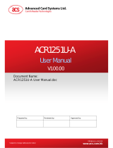
4.0. Architecture
For communication architecture, the protocol used between ACR1252U and the computer is CCID
protocol. All communications between PICC and SAM are PC/SC compliant.
Figure 1: ACR1252U Architecture
ACR1252 PCSC
SAM Interface
PCSC Layer
ISO 7816 Parts 1-4
SAM Interface
ISO 14443 Parts 1-4 /
ISO 18092
PICC Interface
SAM (Socket)
PICC
(Built-in Antenna)
USB
Interface
(CCID)
Physical
Interface
ACR1252U
ACR1252 PCSC
PICC Interface
T=CL & T=1
Emulation

ACR1252U – Application Programming Interface info@acs.com.hk
Version 1.09
www.acs.com.hk
Page 8 of 80
5.0. Host Programming (PC-linked) API
5.1. PCSC API
This section will describe some of the PCSC API for application programming usage. For more
details, please refer to Microsoft MSDN Library or PCSC workgroup.
5.1.1. SCardEstablishContext
The SCardEstablishContext function establishes the resource manager context within which database
operations are performed.
Refer to:
http://msdn.microsoft.com/en-us/library/windows/desktop/aa379479%28v=vs.85%29.aspx
5.1.2. SCardListReaders
The SCardListReaders function provides the list of readers within a set of named reader groups,
eliminating duplicates.
The caller supplies a list of reader groups, and receives the list of readers within the named groups.
Unrecognized group names are ignored. This function only returns readers within the named groups
that are currently attached to the system and available for use.
Refer to:
http://msdn.microsoft.com/en-us/library/windows/desktop/aa379793%28v=vs.85%29.aspx
5.1.3. SCardConnect
The SCardConnect function establishes a connection (using a specific resource manager context)
between the calling application and a smart card contained by a specific reader. If no card exists in
the specified reader, an error is returned.
Refer to:
http://msdn.microsoft.com/en-us/library/windows/desktop/aa379473%28v=vs.85%29.aspx
5.1.4. SCardControl
The SCardControl function gives you direct control of the reader. You can call it any time after a
successful call to SCardConnect and before a successful call to SCardDisconnect. The effect on the
state of the reader depends on the control code.
Refer to:
http://msdn.microsoft.com/en-us/library/windows/desktop/aa379474%28v=vs.85%29.aspx
Note: Commands from
Peripherals Control are using this API for sending.
5.1.5. ScardTransmit
The SCardTransmit function sends a service request to the smart card and expects to receive data
back from the card.
Refer to:
http://msdn.microsoft.com/en-us/library/windows/desktop/aa379804%28v=vs.85%29.aspx
Note: APDU Commands (i.e. the commands sent to connected card and
Pseudo APDU for
Contactless Interface) are using this API for sending.
5.1.6. ScardDisconnect
The SCardDisconnect function terminates a connection previously opened between the calling
application and a smart card in the target reader.
Refer to:
http://msdn.microsoft.com/en-us/library/windows/desktop/aa379475%28v=vs.85%29.aspx

ACR1252U – Application Programming Interface info@acs.com.hk
Version 1.09
www.acs.com.hk
Page 9 of 80
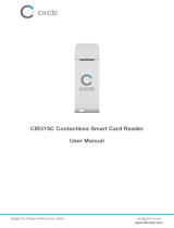
5.1.7. APDU Flow
Figure 2: ACR1252U APDU Flow
SCardEstablishContext
SCardListReaders
Reader
present?
SCardConnect
Connection
successful?
SCardTransmit
SCardDisconnect
Start
End
Yes
No
Yes
No

ACR1252U – Application Programming Interface info@acs.com.hk
Version 1.09
www.acs.com.hk
Page 10 of 80
5.1.8. Escape Command Flow
Figure 3: ACR1252U Escape Command Flow
SCardEstablishContext
SCardListReaders
Reader
present?
SCardConnect
SCardControl
SCardDisconnect
Start
End
Yes
No

ACR1252U – Application Programming Interface info@acs.com.hk
Version 1.09
www.acs.com.hk
Page 11 of 80
5.2. Contactless Smart Card Protocol
5.2.1. ATR Generation
If the reader detects a PICC, an ATR will be sent to the PCSC driver for identifying the PICC.
5.2.1.1. ATR Format for ISO 14443 Part 3 PICCs
Byte Value Designation Description
0 3Bh Initial Header
1 8Nh T0
Higher nibble 8 means: no TA1, TB1, TC1 only
TD1 is following.
Lower nibble N is the number of historical bytes
(HistByte 0 to HistByte N-1)
2 80h TD1
Higher nibble 8 means: no TA2, TB2, TC2 only
TD2 is following.
Lower nibble 0 means T = 0
3 01h TD2
Higher nibble 0 means no TA3, TB3, TC3, TD3
following.
Lower nibble 1 means T = 1
4
To
3+N
80h T1
Category indicator byte, 80 means A status
indicator may be present in an optional
COMPACT-TLV data object
4Fh
Tk
Application identifier Presence Indicator
0Ch Length
RID
Registered Application Provider Identifier (RID) #
A0 00 00 03 06
SS Byte for standard
C0 .. C1h Bytes for card name
00 00 00 00h RFU RFU # 00 00 00 00
4+N UU TCK Exclusive-oring of all the bytes T0 to Tk
Example:
ATR for MIFARE Classic 1K = {3B 8F 80 01 80 4F 0C A0 00 00 03 06 03 00 01 00 00 00 00 6Ah}
Where:
Length (YY) = 0Ch
RID = {A0 00 00 03 06h} (PC/SC Workgroup)
Standard (SS) = 03h (ISO 14443A, Part 3)
Card Name (C0 .. C1) = {00 01h} (MIFARE Classic 1K)
Standard (SS) = 03h: ISO 14443A, Part 3
= 11h: FeliCa

ACR1252U – Application Programming Interface info@acs.com.hk
Version 1.09
www.acs.com.hk
Page 12 of 80
Card Name (C0 .. C1)
00 01: MIFARE Classic 1K
00 38: MIFARE Plus SL2 2K
00 02: MIFARE Classic 4K
00 39: MIFARE Plus SL2 4K
00 03: MIFARE Ultralight
00 30: Topaz and Jewel
00 26: MIFARE Mini
00 3B: FeliCa
00 3A: MIFARE Ultralight C
FF 28: JCOP 30
00 36: MIFARE Plus SL1 2K
FF [SAK]: undefined tags
00 37: MIFARE Plus SL1 4K
5.2.1.2. ATR Format for ISO 14443 Part 4 PICCs
Byte Value Designation Description
0 3Bh Initial Header
1 8Nh T0
Higher nibble 8 means: no TA1, TB1, TC1 only
TD1 is following.
Lower nibble N is the number of historical bytes
(HistByte 0 to HistByte N-1)
2 80h TD1
Higher nibble 8 means: no TA2, TB2, TC2 only
TD2 is following.
Lower nibble 0 means T = 0
3 01h TD2
Higher nibble 0 means no TA3, TB3, TC3, TD3
following.
Lower nibble 1 means T = 1
4
to
3 + N
XX T1 Historical Bytes:
ISO 14443-A:
The historical bytes from ATS response. Refer to
the ISO14443-4 specification.
ISO 14443-B:
Byte1-4 Byte5-7 Byte8
Application
Data from
ATQB
Protocol Info
Byte from
ATQB
Higher
nibble=MBLI
from ATTRIB
command
Lower nibble
(RFU)=0
XX
XX
XX
Tk
4+N UU TCK Exclusive-oring of all the bytes T0 to Tk

ACR1252U – Application Programming Interface info@acs.com.hk
Version 1.09
www.acs.com.hk
Page 13 of 80
Example 1:
ATR for MIFARE® DESFire® = {3B 81 80 01 80 80h} // 6 bytes of ATR
Note: Use the APDU “FF CA 01 00 00h” to distinguish the ISO 14443A-4 and ISO 14443B-4 PICCs,
and retrieve the full ATS if available. ISO 14443A-3 or ISO 14443B-3/4 PICCs do have ATS returned.
APDU Command = FF CA 01 00 00h
APDU Response = 06 75 77 81 02 80 90 00h
ATS = {06 75 77 81 02 80h}
Example 2:
ATR for EZ-Link = {3B 88 80 01 1C 2D 94 11 F7 71 85 00 BEh}
Application Data of ATQB = 1C 2D 94 11h
Protocol Information of ATQB = F7 71 85h
MBLI of ATTRIB = 00h

ACR1252U – Application Programming Interface info@acs.com.hk
Version 1.09
www.acs.com.hk
Page 14 of 80
5.3. Pseudo APDU for Contactless Interface
5.3.1. Get Data
This command returns the serial number or ATS of the “connected PICC”.
Get UID APDU Format (5 Bytes)
Command Class INS P1 P2 Le
Get Data FFh CAh
00h
01h
00h
00h
(Max Length)
If P1 = 00h, Get UID Response Format (UID + 2 Bytes)
Response Data Out
Result
UID
(LSB)
… …
UID
(MSB)
SW1 SW2
If P1 = 01h, Get ATS of a ISO 14443 A card (ATS + 2 Bytes)
Response Data Out
Result ATS SW1 SW2
Response Codes
Results SW1 SW2 Meaning
Success 90h 00h The operation is completed successfully.
Warning 62h 82h
End of UID/ATS reached before Le bytes (Le
is greater than UID Length).
Error 6Ch
XXh
Wrong length (wrong number Le: ‘XX’
encodes the exact number) if Le is less than
the available UID length.
Error 63h 00h The operation is failed.
Error 6Ah 81h Function not supported
Examples:
To get the serial number of the “connected PICC”:
UINT8 GET_UID[5] = {FF, CA, 00, 00, 00};
To get the ATS of the “connected ISO 14443 A PICC”:
UINT8 GET_ATS[5] = {FF, CA, 01, 00, 00};

ACR1252U – Application Programming Interface info@acs.com.hk
Version 1.09
www.acs.com.hk
Page 15 of 80
5.4. APDU commands for PCSC 2.0 Part 3 (version 2.02 or above)
PCSC2.0 Part 3 commands are used to transparently pass data from an application to a contactless
tag, return the received data transparently to the application and protocol, and switch the protocol
simultaneously.
5.4.1. Command and Response APDU Format
Command Format
CLA INS P1 P2 Lc Data In
FFh C2h 00h Function DataLen Data[DataLen]
Where:
Functions 1 byte.
00h = Manage Session
01h = Transparent Exchange
02h = Switch Protocol
Other = RFU
Response Format
Data Out SW1 SW2
Data Field BER-TLV encoded
Every command returns SW1 and SW2 together with the response data field (if available). The SW1
SW2 is based on ISO 7816. SW1 SW2 from the C0 data object below should also be used.
C0 data element Format
Tag Length (1 byte) SW2
C0h 03h Error Status
Error Status Description
Error Status Description
XX SW1 SW2
XX = number of the bad data object in the APDU
00 = general error of APDU
01 = error in the 1
st
data object
02 = error in the 2
nd
data object
00 90 00h No error occurred
XX 62 82h Data object XX warning, requested information not available
XX 63 00h No information
XX 63 01h Execution stopped due to failure in other data object
XX 6A 81h Data object XX not supported
XX 67 00h Data object XX with unexpected length

ACR1252U – Application Programming Interface info@acs.com.hk
Version 1.09
www.acs.com.hk
Page 16 of 80
Error Status Description
XX 6A 80h Data object XX with unexpected vale
XX 64 00h Data Object XX execution error (no response from IFD)
XX 64 01h Data Object XX execution error (no response from ICC)
XX 6F 00h Data object XX failed, no precise diagnosis
The first value byte indicates the number of the erroneous data object XX, while the last two bytes
indicate the explanation of the error. SW1 SW2 values based on ISO 7816 are allowed.
If there are more than one data object in the C-APDU field and one data object failed, IFD can
process the following data objects if they do not depend on the failed data objects.

ACR1252U – Application Programming Interface info@acs.com.hk
Version 1.09
www.acs.com.hk
Page 17 of 80
5.4.2. Manage Session Command
This command is used to manage the transparent session. This includes starting and ending a
transparent session. Through this command, you can also manage the operation environment and the
capabilities of the IFD within the transparent session.
Manage Session Command
Command Class INS P1 P2 Lc Data In
Manage Session FFh C2h 00h 00h DataLen
DataObject
(N bytes)
Where:
Data Object (1 byte)
Tag Data Object
80h Version Data Object
81h Start Transparent Session
82h End Transparent Session
83h Turn Off RF Field
84h Turn On RF Field
5F 46h Timer
FF 6Dh Get Parameter
FF 6Eh Set Parameter
Manage Session Response Data Object
Tag Data Object
C0h Generic Error status
80h Version data object
FF 6Dh IFD parameter data object
5.4.2.1. Start Session Data Object
This command is used to start a transparent session. Once the session has started, auto-polling will
be disabled until the session is ended.
Start Session Data Object
Tag Length (1 byte) Value
81h 00h -

ACR1252U – Application Programming Interface info@acs.com.hk
Version 1.09
www.acs.com.hk
Page 18 of 80
5.4.2.2. End Session Data Object
This command ends the transparent session. The auto-polling will be reset to the state before the
session has started.
End Session Data Object
Tag Length (1 byte) Value
82h 00h -
5.4.2.3. Version Data Object
This command returns the version number of the IFD handler.
Version Data Object
Tag Length (1 byte) Value
80h 03h Major Minor
Build
5.4.2.4. Turn Off the RF Data Object
This command turns off the antenna field.
Turn off RF Field Data Object
Tag Length (1 byte) Value
83h 00h -
5.4.2.5. Turn On the RF Data Object
This command turns on the antenna field.
Turn on the RF Field Data Object
Tag Length (1 byte) Value
84h 00h -
5.4.2.6. Timer Data Object
This command creates a 32-bit timer data object in unit of 1 µs.
Example: If there is timer data object with 5000 µs between RF Turn Off Data Object and RF Turn
On Data Object, the reader will turn off the RF field for about 5000µs before it is turned on.
Timer Data Object
Tag Length (1 byte) Value
5F 46h 04h Timer (4 bytes)

ACR1252U – Application Programming Interface info@acs.com.hk
Version 1.09
www.acs.com.hk
Page 19 of 80
5.4.2.7. Get Parameter Data Object
This command gets the different parameters from the IFD.
Get Parameter Data Object
Tag Length (1 byte)
Value
Tag Len Value
FF 6Dh Var TLV_Objects
TLV_Objects
Parameters Requested Tag Length
Frame size for IFD integer (FSDI) 01h 00h
Frame size for ICC integer (FSCI) 02h 00h
Frame waiting time integer (FWTI) 03h 00h
Max. Communication Speed supported by the IFD 04h 00h
Communication Speed of the ICC 05h 00h
Modulation Index 06h 00h
PCB for ISO/IEC14443 07h 00h
CID for ISO/IEC14443 08h 00h
NAD for ISO/IEC14443 09h 00h
Param 1 – 4 for for ISO/IEC14443 type B 0Ah 00h
5.4.2.8. Set Parameter Data Object
This command sets different parameters from the IFD.
Set Parameter Data Object
Tag Length (1 byte)
Value
Tag Len Value
FF 6Eh Var TLV_Objects
TLV_Objects
Parameters Requested Tag Length
Frame size for IFD integer (FSDI) 01h 01h
Frame size for ICC integer (FSCI) 02h 01h
Frame waiting time integer (FWTI) 03h 01h
Max. Communication Speed supported by the IFD 04h 01h
Communication Speed of the ICC 05h 01h
Modulation Index 06h 01h

ACR1252U – Application Programming Interface info@acs.com.hk
Version 1.09
www.acs.com.hk
Page 20 of 80
Parameters Requested Tag Length
PCB for ISO/IEC14443 07h 01h
CID for ISO/IEC14443 08h 01h
NAD for ISO/IEC14443 09h 01h
Param 1 – 4 for for ISO/IEC14443 type B 0Ah 04h
/