Page is loading ...

VersaView 6186-M
Industrial Flat
Panel Monitors
1200M, 1500M, 1700M, 2000M
User Manual
Allen-Bradley Spares

Important User Information
Solid state equipment has operational characteristics differing from those of
electromechanical equipment. Safety Guidelines for the Application,
Installation and Maintenance of Solid State Controls (Publication SGI-1.1
available from your local Rockwell Automation sales office or online at
http://www.ab.com/manuals/gi) describes some important differences
between solid state equipment and hard-wired electromechanical devices.
Because of this difference, and also because of the wide variety of uses for
solid state equipment, all persons responsible for applying this equipment
must satisfy themselves that each intended application of this equipment is
acceptable.
In no event will Rockwell Automation, Inc. be responsible or liable for
indirect or consequential damages resulting from the use or application of
this equipment.
The examples and diagrams in this manual are included solely for illustrative
purposes. Because of the many variables and requirements associated with
any particular installation, Rockwell Automation, Inc. cannot assume
responsibility or liability for actual use based on the examples and diagrams.
No patent liability is assumed by Rockwell Automation, Inc. with respect to
use of information, circuits, equipment, or software described in this manual.
Reproduction of the contents of this manual, in whole or in part, without
written permission of Rockwell Automation, Inc. is prohibited.
Throughout this manual we use notes to make you aware of safety
considerations.
WARNING
Identifies information about practices or circumstances
that can cause an explosion in a hazardous environment,
which may lead to personal injury or death, property
damage, or economic loss.
IMPORTANT
Identifies information that is critical for successful
application and understanding of the product.
ATTENTION
Identifies information about practices or circumstances
that can lead to personal injury or death, property
damage, or economic loss. Attentions help you:
• identify a hazard
• avoid a hazard
• recognize the consequence
SHOCK HAZARD
Labels may be located on or inside the drive to alert
people that dangerous voltage may be present.
BURN HAZARD
Labels may be located on or inside the drive to alert
people that surfaces may be dangerous temperatures.

1 Publication 6186M-UM001D-EN-P
Table of Contents
Preface
Who Should Use This Manual . . . . . . . . . . . . . . . . . . Preface-1
Purpose of This Manual. . . . . . . . . . . . . . . . . . . . . . . Preface-1
Contents of This Manual . . . . . . . . . . . . . . . . . . . . . . Preface-2
Manual Conventions . . . . . . . . . . . . . . . . . . . . . . . . . Preface-3
Allen-Bradley Support . . . . . . . . . . . . . . . . . . . . . . . . Preface-3
Chapter 1
System Features
Description. . . . . . . . . . . . . . . . . . . . . . . . . . . . . . . . . . . . 1-1
Package Contents . . . . . . . . . . . . . . . . . . . . . . . . . . . . . . . 1-1
Part Numbers . . . . . . . . . . . . . . . . . . . . . . . . . . . . . . . . . . 1-2
Chapter 2
Installation
Before Unpacking the Monitor. . . . . . . . . . . . . . . . . . . . . . 2-1
Hazardous Locations . . . . . . . . . . . . . . . . . . . . . . . . . . . . . 2-1
Installation Guidelines. . . . . . . . . . . . . . . . . . . . . . . . . . . . 2-2
Enclosures . . . . . . . . . . . . . . . . . . . . . . . . . . . . . . . . . . . . 2-3
Mounting Dimensions . . . . . . . . . . . . . . . . . . . . . . . . . . . . 2-4
VersaView 1200M Mounting Dimensions. . . . . . . . . . . . 2-4
VersaView 1500M Mounting Dimensions. . . . . . . . . . . . 2-4
VersaView 1700M Mounting Dimensions. . . . . . . . . . . . 2-5
VersaView 2000M Mounting Dimensions. . . . . . . . . . . . 2-5
Mounting Cutouts . . . . . . . . . . . . . . . . . . . . . . . . . . . . . . . 2-6
Installing Monitor in Panel. . . . . . . . . . . . . . . . . . . . . . . . . 2-7
Mounting Hardware . . . . . . . . . . . . . . . . . . . . . . . . . . . 2-7
Tools Required . . . . . . . . . . . . . . . . . . . . . . . . . . . . . . 2-7
Panel Mounting Guidelines . . . . . . . . . . . . . . . . . . . . . 2-8
Installing Panel Mount Monitor. . . . . . . . . . . . . . . . . . . 2-8
Installing Monitor in a Rack. . . . . . . . . . . . . . . . . . . . . . . . 2-10
Tools Needed for Rack Mount Installation. . . . . . . . . . . 2-10
Rack Mounting Guidelines . . . . . . . . . . . . . . . . . . . . . . 2-10
Installing Monitor Into a Rack. . . . . . . . . . . . . . . . . . . . 2-11
Installing Monitor on a Bench or Tabletop . . . . . . . . . . . . . 2-12
Tools Needed for Arm Mounting . . . . . . . . . . . . . . . . . 2-12
Bench/Tabletop Mounting Guidelines. . . . . . . . . . . . . . 2-12
Mounting Monitor on a Benchtop or Tabletop . . . . . . . 2-13
Installing Monitor on Wall . . . . . . . . . . . . . . . . . . . . . . . . . 2-14
Tools Needed for Wall Mounting . . . . . . . . . . . . . . . . . 2-14
Mounting Monitor on a Wall. . . . . . . . . . . . . . . . . . . . . 2-14
Making Connections . . . . . . . . . . . . . . . . . . . . . . . . . . . . . 2-15
Monitor Connections . . . . . . . . . . . . . . . . . . . . . . . . . . 2-15
Connecting a Host Video Source . . . . . . . . . . . . . . . . . 2-16
Connecting the Optional Touchscreen Interface . . . . . . 2-16
Connecting AC Power . . . . . . . . . . . . . . . . . . . . . . . . . 2-17
Connecting DC Power (Terminal Block, VersaView 1500M,
1700M, 2000M Only) . . . . . . . . . . . . . . . . . . . . . . . . . . 2-18
Securing Cables . . . . . . . . . . . . . . . . . . . . . . . . . . . . . . 2-19
Allen-Bradley Spares

Publication 6186M-UM001D-EN-P
Table of Contents 2
Chapter 3
Configuring the Video Setup
Chapter Objective . . . . . . . . . . . . . . . . . . . . . . . . . . . . . . . 3-1
Setting the Monitor Type . . . . . . . . . . . . . . . . . . . . . . . . . . 3-1
Checking and Changing
the Display Resolution . . . . . . . . . . . . . . . . . . . . . . . . . . . 3-2
Adjusting Your Monitor . . . . . . . . . . . . . . . . . . . . . . . . . . . 3-4
Chapter 4
Performing Routine Maintenance
Chapter Objective . . . . . . . . . . . . . . . . . . . . . . . . . . . . . . . 4-1
Cleaning . . . . . . . . . . . . . . . . . . . . . . . . . . . . . . . . . . . . . . 4-1
Replacing a Line Cord . . . . . . . . . . . . . . . . . . . . . . . . . . . . 4-1
Other Maintenance . . . . . . . . . . . . . . . . . . . . . . . . . . . . . . 4-1
Chapter 5
System Troubleshooting
Chapter Objective . . . . . . . . . . . . . . . . . . . . . . . . . . . . . . . 5-1
Self-Test . . . . . . . . . . . . . . . . . . . . . . . . . . . . . . . . . . . . . . 5-1
Troubleshooting Solutions . . . . . . . . . . . . . . . . . . . . . . . . . 5-2
Allen-Bradley Support . . . . . . . . . . . . . . . . . . . . . . . . . . . . 5-3
Appendix A - Touchscreen Serial Interface
Appendix B - Video Cables
Appendix C - Product Specifications

1 Publication 6186M-UM001D-EN-P
Preface
Read this preface to familiarize yourself with the rest of the manual.
The preface covers the following topics:
• who should use this manual
• the purpose of the manual
• the contents of the manual
• conventions used in this manual
• Allen-Bradley support
Who Should Use This
Manual
Use this manual if you are responsible for installing, using, or
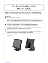
troubleshooting VersaView 6186-M Industrial Flat Panel Monitors.
Purpose of This Manual
This manual is a user guide for the VersaView 6186-M Industrial Flat
Panel Monitors. It gives an overview of the system and describes
procedures used to:
• install a 6186-M monitor in a panel or enclosure
• make connections to a 6186-M monitor
• configure a 6186-M monitor’s video setup
• troubleshoot a 6186-M monitor
Allen-Bradley Spares

Publication 6186M-UM001D-EN-P
Preface 2
Contents of This Manual
Chapter Title Contents
Preface Describes the purpose, background and
scope of this manual. Also specifies the
intended audience.
1 System Features Describes the features and capabilities of
the 6186-M monitors.
2 Installation Explains how to install a 6186-M monitor in
a panel, rack, bench/tabletop, or wall. Also,
how to connect power and external video
sources.
3 Configuiring the Video Setup Explains how to setup and configure
6186-M monitors.
4 Performing Routine
Maintenance
Describes cleaning and other maintenance.
5 System Troubleshooting Explains how to interpret and correct
problems with the 6186-M monitors.
Appendix A Touchscreen Serial Interface Describes setting up and enabling the
touchscreen for 6186-M monitors equipped
with a touchscreen interface.
Appendix B Video Cables Describes the HD-15 or DVI connector
cables you can use to connect your monitor
to the host computer.
Appendix C Product Specifications Specifications for the 6186-M monitors.

Publication 6186M-UM001D-EN-P
Preface 3
Manual Conventions
The following conventions are used throughout this manual:
• Bulleted lists such as this one provide information, not
procedural steps.
• Numbered lists provide sequential steps or hierarchical
information.
Allen-Bradley Support
Allen-Bradley offers support services worldwide, with over 75
Sales/Support Offices, 512 authorized Distributors and 260 authorized
Systems Integrators located throughout the United States, plus
Allen-Bradley representatives in every major country in the world.
Local Product Support
Contact your local Allen-Bradley representative for:
• sales and order support
• product technical training
• warranty support
• support service agreements
Technical Product Assistance
Before you contact Rockwell Automation for technical assistance,
please review the troubleshooting information contained in this
publication.
If the problem persists, call your local Rockwell Automation
representative, or contact Rockwell Automation in one of the
following ways:
Phone United
States/Canada
1.440.646.5800
Outside United
States/Canada
You can access the phone number for your
country via the Internet:
1. Go to http://www.ab.com
2. Click on Product Support
(http://support.automation.rockwell.com)
3. Under Support Centers, click on Contact
Information
Internet
⇒
1. Go to http://www.ab.com
2. Click on Product Support
(http://support.automation.rockwell.com)
Allen-Bradley Spares

Publication 6186M-UM001D-EN-P
Preface 4

1 Publication 6186M-UM001D-EN-P
Chapter
1
System Features
Description
The VersaView 6186-M Industrial Flat Panel Monitor offers the
following:
• Bright (250 nits) 16.7M color (24-bit) Active Matrix TFT display
• Video formats supported from 640x480 to 1600x1200
• Wide viewing angles
• Optional resistive and capacitive antiglare touchscreens
• One-button automatic screen setup
• Rear panel keypad with lockout feature
• NEMA Types 1, 12, 4X (indoor use only) and IP65
equivalent ratings
• 90…264V AC, 12V DC, or 24V DC input power supply
• Space efficient enclosure (<2.9 in. [74 mm] deep)
• Optional rack, bench, and wall mount adapter brackets
Package Contents
The shipping cartons contain the following items:
• Monitor
• CD containing ScreenSet Monitor Setup Utility, drivers, and
documentation
• Package of panel mounting hardware
• AC power adapter and cord
• HD-15 Video cable
• Stylus (monitors with touchscreen option only)
• RS-232 serial extension cable (monitors with touchscreen option
only)
• Cable retention tie wraps
• installation guide
Allen-Bradley Spares

Publication 6186M-UM001D-EN-P
1-2 System Features
Part Numbers
Catalog Number Display Size Bezel Touchscreen
6186-M12AL 12 inch Aluminum None
6186-M12ALTR Resistive Touch
6186-M15AL 15 inch Aluminum None
6186-M15ALTR Resistive Touch
6186-M15ALTC Capacitive Touch
6186-M15SS Stainless Steel None
6186-M15SSTR Resistive Touch
6186-M17AL 17 inch Aluminum None
6186-M17ALTR Resistive Touch
6186-M17ALTC Capacitive Touch
6186-M17SS Stainless Steel None
6186-M17SSTR Resistive Touch
6186-M20AL 20 inch Aluminum None
6186-M20ALTR Resistive Touch
6186-M20RK Rack Mount only
Aluminum
None
6186-M20RKTR Resistive Touch
6186-M20SS Stainless Steel None
6186-M20SSTR Resistive Touch
VersaView Monitor Mounting Adapters Cat. No.
1200M Rack Adapter 6189V-MRA12
1500M Rack Adapter 6189V-MRA15
1700M Rack Adapter 6189V-MRA17
Bench/Table Top Adapter (all models) 6189V-MBA
Wall Mount Adapter (all models) 6189V-MWA
6185-B to 1200M Mounting Adapter 6189V-MMA12
6185-C/6185-H to 1500M Mounting Adapter 6189V-MMA15
6185-D/6185-J to 1700M Mounting Adapter 6189V-MMA17
Mounting Clips 6189V-CLPS
VersaView Monitor Cables and Power Supplies Cat. No.
Analog Video Cable, 4.6 m (15 ft) 6189-SDNC21
Touch Screen Cable, 4.6 m (15 ft) 6189-SE2903
External AC Power Supply, 90…264V ac 6189V-MPS
External AC Power Supply DIN Rail Mounting Kit 6189V-MMAPS
Digital Video Cable, 2 m (6.5 ft) 6189V-DVICBL2
Digital Video Cable, 5 m (16.4 ft) 6189V-DVICBL5

1 Publication 6186M-UM001D-EN-P
Chapter
2
Installation
Before Unpacking the
Monitor
Before unpacking your new monitor, inspect the shipping carton for
damage. If damage is visible, immediately contact the shipper and
request assistance. Otherwise, proceed with unpacking.
Hazardous Locations
This equipment is suitable for:
• Class I, Division 2 Groups A, B, C, D
• Class II, Division 2 Groups F, G
• Class III, Division 1
• or non-hazardous locations
The following statement applies to use in hazardous locations.
The VersaView Flat Panel Monitors and AC adapter have an operating
temperature code of T4 (maximum operating temperature of 55°C or
131°F). Do not install the terminals in environments where
atmospheric gases have ignition temperature less than 55°C or 131°F.
TIP
Make sure you keep all the original packaging for
the monitor in case you need to return the monitor
for repair. Both the inner and outer packing cartons
should be used to ensure adequate protection for
any units returned for service.
WARNING
Explosion Hazard
• Substitution of components may impair
suitability for hazardous locations.
• Do not disconnect equipment unless power has
been switched off and area is known to be
non-hazardous.
• Do not connect or disconnect components
unless power has been switched off.
• All wiring must comply with N.E.C articles
501-4(b), 502-4(b), 503-3(b) as appropriate.
• Peripheral equipment must be suitable for the
location it is used in.
Allen-Bradley Spares

Publication 6186M-UM001D-EN-P
2-2 Installation
Installation Guidelines
Follow these guidelines to help ensure that the monitor provides safe
and reliable service.
• Ensure that sufficient power is available at the site.
Do not install the terminals in environments where atmospheric gases
have ignition temperature less than 55°C or 131°F.
• Ensure that sufficient space is available around air inlets and
outlets to provide the circulation necessary for cooling. Never
allow air passages to become obstructed.
• The ambient air temperature must not exceed the specified
maximum temperature. You may need a user-supplied fan, heat
exchanger, or air conditioner to meet this condition in some
installations.
• The humidity of the ambient air must not exceed specified
limits. In very dry environments, static charges build up very
readily. Proper grounding of the equipment through the AC
power cord can help reduce the likelihood of static discharges,
which may cause shocks and damage electronic components.
• Leave the monitor's enclosure or cover in place at all times
during operation. The cover provides protection against high
voltages inside the monitor and inhibits radio-frequency
emissions that might interfere with other equipment.
ATTENTION
In order to maintain an electrically safe installation, a
6186-M monitor must be connected to Earth ground
when installed. Installing 6186-M in a panel,
enclosure or rack that is already connected to Earth
ground will satisfy this requirement. Otherwise,
connect your monitor to Earth ground using a
16 AWG or larger external wire.
The ground wire should have green insulation with
a yellow stripe for easy identification.
TIP
Remember that heat rises. The temperature at the
top of an enclosure is often much higher than the
rest of the enclosure if air is not circulating.
IMPORTANT
This monitor is designed to operate at a range of
extremes. However, you should not continuously
operate the monitor at the highest end of the
specified temperature range.
While the product will operate at its highest
specified temperature, the overall life span of any
electronic device is shortened when it operates at its
highest rated temperature.

Publication 6186M-UM001D-EN-P
Installation 2-3
Enclosures
Mount the VersaView monitor in a panel or enclosure to protect the
internal circuitry. All units that are not rack-mount, ship with a
gasketed bezel to meet NEMA Type 1, 12, 4X (indoor use only) and
IEC IP65 only when mounted in a panel or enclosure with an
equivalent rating.
ATTENTION
Environment and Enclosure
This equipment is intended for use in a Pollution
Degree 2 industrial environment, in overvoltage
Category II applications (as defined in IEC
publication 60664-1), at altitudes up to 2000 meters
without derating.
This equipment is considered Group 1, Class A
industrial equipment according to IEC/CISPR
Publication 22. Without appropriate precautions,
there may be potential difficulties ensuring
electromagnetic compatibility in other environments
due to conducted, as well as radiated, disturbance.
This equipment is supplied as “open type”
equipment. It must be mounted within an enclosure
that is suitably designed for those specific
environmental conditions that will be present and
appropriately designed to prevent personal injury
resulting from accessibility to live parts. The interior
of the enclosure must be accessible only by the use
of a tool. Subsequent sections of this publication
may contain additional information regarding
specific enclosure type ratings that are required to
comply with certain product safety certifications.
See NEMA Standards publication 250 and IEC
publication 60529, as applicable, for explanations of
the degrees of protection provided by different types
of enclosure. Also, see the appropriate sections in
this publication, as well as the Allen-Bradley
publication 1770-4.1 (“Industrial Automation Wiring
and Grounding Guidelines”), for additional
installation requirements pertaining to this
equipment.
Allen-Bradley Spares

Publication 6186M-UM001D-EN-P
2-4 Installation
Mounting Dimensions
The following illustrations show the mounting dimensions for the
VersaView 6186-M Industrial Flat Panel Monitor. All measurements are
in mm [inches].
VersaView 1200M Mounting Dimensions
VersaView 1500M Mounting Dimensions
Mounting clip slots for panel mounting
(see page 2-8 for details)
224.0 [8.82]
110.0 [4.33]
31.2 [1.23]
56.10 [2.21]
110.0 [4.33]
340.0 [13.39]
260.0 [10.24]
235.0 [9.25]
315.0 [12.40]
8.0 [0.31]
56.1 [2.21]
Mounting clip slots for
panel mounting
(see page 2-8 for details)
410.00 [16.14]
383.6 [15.10]
281.9 [11.10]
160.0 [6.30]
160.0 [6.30]
58.0 [2.28]
29.5 [1.16]
309.0 [12.2]
140.0 [5.51]
282.6 [11.13]
8.0 [0.31]
58.0 [2.28]

Publication 6186M-UM001D-EN-P
Installation 2-5
VersaView 1700M Mounting Dimensions
VersaView 2000M Mounting Dimensions
Mounting clip slots for panel
mounting (see page 2-8 for details)
326.0 [12.84]
422.0 [16.61]
150.00 [5.91]150.00 [5.91]
54.8 [2.16]
30.2 [1.19]
452.0 [17.80]
356.0 [14.02]
8.0 [0.31]
54.8 [2.16]
160.0 [6.30]
328.0 [12.91]
447 [17.6]
116 [4.57]
319.3 [12.57]
116 [4.57]110 [4.33]
483 [19.0]
17.8 [0.685]
74 [2.9]
399 [15.7]]
362 [14.25]
120 [4.72]
120 [4.72]
Mounting clip slots for
panel mounting
(see page 2-8 for details)
34.6 [1.36]
Allen-Bradley Spares

Publication 6186M-UM001D-EN-P
2-6 Installation
Mounting Cutouts
The following figure provides the dimensions for making a panel or
enclosure cutout for the VersaView 6186-M Industrial Flat Panel
Monitor. All measurements are in mm [inches].
Conversion
Adapters
Description
6189V-MMA12 Mounting adapter for converting from 6185-B to 1200M
6189V-MMA15 Mounting adapter for converting from 6185-C or J to 1500M
6189V-MMA17 Mounting adapter for converting from 6185-H or D to 1700M
VersaView 1200M Monitor
VersaView 1500M Monitor
VersaView 1700M Monitor
324.0 [12.76]
386.6 [15.22]
424.0 [16.69]
254.0 [10.0]
285.6 [11.24]
329.5 [12.97]
VersaView 2000M Monitor
449.6 [17.70]
363.5 [14.31]

Publication 6186M-UM001D-EN-P
Installation 2-7
Installing Monitor in Panel
Panel mount monitors are designed to provide protection against
water and dust to NEMA Types 1, 12, 4X (indoor use only) or
IP65 equivalent standards.
Slides or shelves are not required because panel mount monitors are
designed to be supported by the panel in which they are installed.
Mounting Hardware
The 6186-M is shipped with the following mounting hardware for
panel mounting:
Tools Required
In addition to the tools required to make the cutout, you will need the
following tools:
• #2 Phillips torque screwdriver
Item Description Used For Quantity
Mounting Clips Panel Mounting 8 (VersaView 1200M)
10 (VersaView 1500M and 1700M)
14 (VersaView 2000M, non
rack-mount versions only)
Allen-Bradley Spares

Publication 6186M-UM001D-EN-P
2-8 Installation
Panel Mounting Guidelines
Observe the following precautions when installing the unit in a panel:
• Confirm that there is adequate space behind the panel.
– Allow at least 26 mm (1.0 in.) on the sides and bottom and
51 mm (2.0 in.) on the top for ventilation.
– A cabinet with a minimum depth of 74 mm (2.9 in.) is
sufficient.
• Take precautions so that metal cuttings do not enter any
components that are already installed in the panel.
• Supporting panels should be at least 14 gauge to ensure proper
sealing against water and dust, and to provide proper support.
The mounting hardware supplied accommodates panels up to
6.25 mm (0.25 in.) thick.
Installing Panel Mount Monitor
1. Prepare panel cutout for monitor. Refer to cutout drawings on
page 2-4.
2. If access to the rear of the monitor is not available following
installation, attach the cables to the monitor at this time. Refer
to Monitor Connections on page 2-15 for complete details.
3. Make sure the monitor’s sealing gasket is properly positioned on
the monitor. This gasket forms a compression type seal. Do not
use sealing compounds.
4. Place the monitor in the panel cutout.
IMPORTANT
Supporting panels must be cut to specifications
before installation.
ATTENTION
Failure to follow these warnings may result in
personal injury or damage to the panel components.

Publication 6186M-UM001D-EN-P
Installation 2-9
5. Install the mounting clips. The mounting clips slide into the slots
on the top, side and bottom of the monitor.
6. Gradually tighten the clips one at a time around the bezel using
the specified sequence. Note that the sequence begins with the
center clips and continues to the corner clips.
Repeat this process at least three times until the clips are
hand-tight and the gasket is compressed uniformly against the
panel.
7. Tighten mounting clips to a torque of 10 in-lbs (1.1 N•m) in the
sequence shown in step 6. Do not over-tighten.
Mounting Clips for VersaView 1500M /1700M
(The number of mounting clips varies by model)
Torque
Sequence
Torque
Sequence
8
157
26
43
715
628
93
410
VersaView 1500M and 1700MVersaView 1200M
Torque
Sequence
14 1 5
13
4
VersaView 2000M
6
11 10 2 9
12
7
3
8
ATTENTION
Tighten mounting clips to a torque of 10 in-lbs (1.1
N•m) to provide a proper seal and prevent damage
to the monitor. Rockwell Automation assumes no
responsibility for water or chemical damage to the
monitor or other equipment within the enclosure
because of improper installation.
Allen-Bradley Spares

Publication 6186M-UM001D-EN-P
2-10 Installation
Installing Monitor in a Rack
The rack-mount version of the 2000M monitor installs directly into a
rack. You can install other VersaView monitors into a rack using the
appropriate rack adapter:
Tools Needed for Rack Mount Installation
You will need the following tools:
• Rack adapter kit
• #2 Phillips screwdriver
Rack Mounting Guidelines
Observe the following precautions when installing this unit in a rack:
• The cabinet must be tall enough to accommodate the monitor’s
panel height.
• The cabinet must be deep enough to accommodate the
monitor’s depth while providing rear clearance for cabling and
airflow. The following cabinet depths are sufficient:
– 74 mm (2.9 in.)
• No slides or shelves are required because the rack mount
monitor is designed to be supported by the rack in which it is
installed.
Adapter Catalog Number Description
6189V-MRA12 Rack adapter for VersaView 1200M
6189V-MRA15 Rack adapter for VersaView 1500M
6189V-MRA17 Rack adapter for VersaView 1700M
/