Tripp Lite 1400VA Owner's manual

Category
Uninterruptible power supplies (UPSs)
Type
Owner's manual
Owner’s Manual
1111 W. 35th Street Chicago, IL 60609 USA
Customer Support: (773) 869-1234 • www.tripplite.com
Important Safety Instructions
2
Mounting
3
Connection
6
Basic Operation
8
Storage and Service
11
Español
Copyright ©2002 Tripp Lite. All rights reserved. SmartPro
®
is a registered trademark of Tripp Lite.
SmartPro
®
2U Rackmount
120V Input/Output UPS Systems • Intelligent • Line-Interactive • Extended Run
Models: 1400—3000 VA
13
Battery Replacement
12
Specifications
12
Français
25
200212046 93-2107 SmartPro 2U Owner’s Manual.qxd 1/6/2003 2:21 PM Page 1
2
Important Safety Instructions
SAVE THESE INSTRUCTIONS
This manual contains important instructions that should be followed during the installation,
operation and storage of all Tripp Lite UPS Systems. Failure to heed these warnings will void
your warranty.
UPS Location Warnings
Use caution when lifting UPS. Because of the considerable weight of all Rackmount UPS
systems, at least two people should assist in lifting and installing them.
Install your UPS indoors, away from excess moisture or heat, dust or direct sunlight.
For best performance, the ambient temperature near your UPS should be between 0° C and
40° C (between 32° F and 104° F).
Leave adequate space around all sides of the UPS for proper ventilation. Do not obstruct its
vents or fan openings.
UPS Connection Warnings
The UPS contains its own energy source (battery). The output terminals may be live even
when the UPS is not connected to an AC supply.
Connect your UPS to a properly grounded AC power outlet. Do not modify the UPS’s plug
in a way that would eliminate the UPS's connection to ground. Do not use adapters that
eliminate the UPS’s connection to ground.
Do not plug your UPS into itself; this will damage the UPS and void your warranty.
If you are connecting your UPS to a motor-powered AC generator, the generator must provide
filtered, frequency-regulated computer-grade output. Connecting your UPS to a generator will
void its Ultimate Lifetime Insurance.
Equipment Connection Warnings
Do not use Tripp Lite UPS Systems for life support applications in which a malfunction or
failure of a Tripp Lite UPS System could cause failure or significantly alter the performance
of a life-support device.
Do not connect surge suppressors to the output of your UPS. This may damage your UPS and
will void both the surge suppressor and UPS warranties.
Battery Warnings
Except for battery replacement, your UPS does not require routine maintenance. Do not open
your UPS for any reason. There are no user-serviceable parts inside.
Battery replacement must be performed by qualified service personnel. Because batteries
present a risk of electrical shock and burn from high short-circuit current, qualified service
personnel should observe proper precautions: Use tools with insulated handles and replace
the existing batteries with the same number and type of new batteries (Sealed Lead-Acid).
Do not open the batteries. Do not short or bridge the battery terminals with any object.
During hot-swap battery replacement, the UPS will not provide backup power in the event of
a blackout or other power interruptions.
Do not operate UPS without batteries.
Do not dispose of the batteries in a fire. The UPS batteries are recyclable. Refer to local codes
for disposal requirements, or in the USA only, refer to these sources for recycling information:
• 1-800-SAV-LEAD (1-800-728-5323)
• 1-800-8-BATTERY (1-800-8-228-8379)
• www.rbrc.com
When adding external battery packs, connect only Tripp Lite-recommended battery packs of
the correct voltage and type. Do not connect or disconnect battery packs when the UPS is
operating on battery power.
200212046 93-2107 SmartPro 2U Owner’s Manual.qxd 1/6/2003 2:21 PM Page 2
3
Mounting
Your equipment may be rackmounted in 4-post rack enclosures using the included rack shelves
(UPSRMRII Adjustable Rackmount Shelf Kit) and the following suggested mounting procedures.
These procedures are for common enclosure types and may not be appropriate for all rack enclosures.
You must determine the fitness of rackmount hardware and procedures before mounting. If this
hardware or these procedures are not suitable for your application, contact your rack enclosure’s
manufacturer for a solution.
Mount one piece of equipment in a 4-post rack section using the Single Unit Installation procedure,
or one piece of equipment in a 2-post rack using the 2-Post (Telecom) Installation procedure. If you have
two UPSRMRII shelf kits and a sufficiently deep rack, you may mount two pieces of equipment in
a 4-post rack section using the Back-to-Back Installation procedure. Your UPS also may be positioned
safely in an upright position without mounting screws with the addition of a 2U Tower Stand, sold
separately from Tripp Lite.
Single Unit Installation
Connect the two segments of each shelf (A) using the
included screws and nuts (B). Leave the screws slightly
loose so that the shelves can be adjusted in the next step.
Adjust each shelf to fit your rack, then mount them in
the lowest available space of your rack with the
screws, nuts and washers provided (C). Note that the
support ledges should face inward. Tighten the screws
that connect the shelf segments (B).
Attach mounting ears (D) to the front mounting holes
of your equipment (E) using the screws provided (F).
The ears should face forward.
Using an assistant if necessary, lift your equipment
and slide it onto the mounting shelves. Attach your
equipment to the rack by passing the screws, nuts and
washers provided (G) through its mounting ears and
into the rack rails.
1
2
3
A
B
C
B
E
D
F
G
1
2
3
4
4
200212046 93-2107 SmartPro 2U Owner’s Manual.qxd 1/6/2003 2:21 PM Page 3
4
Mounting
Back-to-Back Installation
Connect the shelved sections from two UPSRMRII
kits (A) to the unshelved sections (B) using the included
screws and nuts (C). Note: Two unshelved sections
will be left over. Leave the screws slightly loose so
that the shelves can be adjusted in the next step.
Adjust each shelf to fit your rack, then mount them in
the lowest available space of your rack with the
screws, nuts and washers provided (D). Note that the
support ledges should face inward. Tighten the screws
that connect the shelf segments (C).
Attach mounting ears (E) to the front mounting holes of
your equipment (F) using the screws provided (G). The
ears should face forward.
Using an assistant if necessary, lift your equipment
and slide it onto the mounting shelves. Attach your
equipment to the rack by passing the screws, nuts and
washers provided (H) through its mounting ears and
into the rack rails.
D
C
F
E
H
G
C
A
B
1
2
3
4
1
2
3
4
200212046 93-2107 SmartPro 2U Owner’s Manual.qxd 1/6/2003 2:22 PM Page 4
5
Color Selection
Select UPS systems can be configured to match black or grey equipment. To match grey equipment,
mount the grey mounting ears in front. To match black equipment, switch the grey front panel on the
unit for the black front panel (included with select models), and mount the black mounting ears in
front. (See mounting instructions for exact mounting ear placement.)
To switch the front panel of the UPS, first unscrew the six screws on the front face of the unit, then
remove the front panel. Next, unscrew the two screws that attach the LED board to the inside of the
front panel, then remove the LED board without disconnecting the ribbon cable that connects it to
the UPS. Screw the LED board to the new front face and screw the new front face to the UPS.
Mounting
2-Post (Telecom) Installation
Mount the shelved sections (A) of your UPSRMRII kit
on the back side of your rack. Mount them in the lowest
available space of your rack with with the screws, nuts
and washers provided (B). Note that the support ledges
should face inward.
Attach mounting ears (C) to the front mounting holes of
your equipment (D) using the screws provided (E). The
ears should face backward.
Using an assistant if necessary, lift your equipment
and slide it onto the mounting shelves. Attach your
equipment to the rack by passing the screws, nuts and
washers provided (F) through its mounting ears and
into the rack rails.
1
2
3
A
D
C
F
B
E
1
2
3
200212046 93-2107 SmartPro 2U Owner’s Manual.qxd 1/6/2003 2:22 PM Page 5
6
Connection
Plug your UPS’s Line Cord into
an electrical outlet.
Once your UPS is plugged in, the UPS will enter STANDBY
mode. The fan will activate and the “ ” LED will
begin flashing. The UPS system’s outlets will not be
active until the UPS is turned ON.
SMART1400RM2U and SMART1500RMXL2U
models require connection to a 15-amp dedicated circuit.
SMART2200RMXL2U and SMART2600RM2U models
are fitted with plugs for connection to a 20-amp dedicated
circuit, but may be reconfigured for use with a 15-amp
dedicated circuit (see “Switching Plugs” below).
SMART3000RM2U models are fitted with twist-lock
plugs for connection to a 30-amp dedicated circuit, but
may be reconfigured for use with a 20-amp dedicated
circuit (see “Switching Plugs” below).
Switching Plugs: Plug switching should only be done
by a qualified electrician. Switching plugs will change
the output capacity of your UPS; see Specifications.
Plug your equipment into your UPS.
Your UPS is designed to support only computer equipment.
You will overload your UPS if you connect household
appliances, laser printers or surge suppressors to the
UPS’s Outlets.
Turn your UPS ON
Press the “POWER” button
• Hold the button for a moment, until the “ ”
LED stops flashing and illuminates constantly
Release the button
Your UPS is now ON and its AC outlets are active.
1
2
1
2
3
SMART2200RMXL2U plug
(NEMA 5-20P) shown
SMART3000RM2U shown
3
200212046 93-2107 SmartPro 2U Owner’s Manual.qxd 1/6/2003 2:22 PM Page 6
7
Connection (optional)
Your UPS will function properly without these connections.
Serial Port Connection
Using the serial cable provided, connect a serial port from a
computer to a serial port on your UPS. Install on the computer
the Tripp Lite power protection software appropriate to its
operating system. If your UPS features two serial ports, a
second serial computer may be connected.
USB Port Connection
Using the USB cable provided, connect a USB port from a
computer to a USB port on your UPS. Install on the comput-
er the Tripp Lite power protection software appropriate to
its operating system. If your UPS features two USB ports,
a second USB computer may be connected.
EPO Port Connection
Using the RJ-11 cable provided, connect the Emergency
Power Off (EPO) port of your UPS to a user-supplied normally
closed or normally open switch according to the circuit diagram
at the right. The EPO port is not a phone line surge
suppressor; do not connect a phone line to this port.
External Battery Pack Connection
Since your UPS has internal batteries, external batteries are
only needed to extend runtime. Adding external batteries
will increase recharge time as well as runtime.
The diagram to the right shows the location of your UPS’s
External Battery Connector, where you will insert the cable that
is attached to your battery pack. Complete installation and
mounting instructions for your battery pack appear in the
battery pack’s owner’s manual. Make sure that cables are fully
inserted into their connectors. Small sparks may result during
battery connection; this is normal.
Serial Connection: SMART3000RM2U shown
USB Connection: SMART3000RM2U shown
EPO Connection: SMART3000RM2U shown
EPO Circuit Diagram
External Battery Connection:
SMART3000RM2U shown
200212046 93-2107 SmartPro 2U Owner’s Manual.qxd 1/6/2003 2:22 PM Page 7
Use the POWER button to switch your UPS between its four modes of operation.
OFF: No indicator lights are on. The UPS is completely shut down for storage
or shipping. If the UPS is connected to AC power, it will start up in STANDBY
mode. If the UPS is not connected to AC power and the POWER button is
pressed for two seconds, the UPS will “cold start” into INVERT mode.
STANDBY: The “ ” light is flashing. The UPS is receiving AC power and
using it to charge its internal batteries, but its outlets are not active. Pressing the
POWER button while the UPS is in STANDBY will put the UPS in the ON
mode. Unplugging the UPS or cutting AC power while the UPS is in STANDBY
will put the UPS in the OFF mode.
ON: The “ ” light is on. The UPS is receiving AC power, charging its bat-
teries and delivering power to connected equipment. If AC power is lost while
the UPS is ON (i.e. a blackout occurs), the UPS will switch into INVERT
mode. Pressing the POWER button while the UPS is ON will put the UPS in
STANDBY mode.
INVERT: The “ ” light is flashing. The UPS is powering connected equip-
ment from battery backup. If AC power is restored, the UPS will switch to the
ON mode. Pressing the POWER button while the UPS is in INVERT will put
the UPS into the OFF mode. If the UPS is in INVERT and its batteries are
drained, the UPS will switch to the OFF mode until AC power is restored, then
switch to the ON mode.
Use the MUTE/TEST button to do two things:
Silence Alarm:Your UPS has three alarms. The first, the INVERT alarm, emits
four short beeps every ten seconds when the UPS is in INVERT mode, to warn
you that AC power has failed. The second, the OVERLOAD alarm, emits short,
rapid beeps when the UPS is in INVERT mode if the total power draw of con-
nected equipment exceeds the UPS's output capacity, to warn you to reduce the
load. The third, the Low Battery alarm, emits a constant beep when the UPS is
in INVERT mode and its batteries are very nearly depleted, to warn you that
connected equipment must shut down. To silence the INVERT or OVERLOAD
alarms, press the MUTE/TEST button. The LOW BATTERY alarm will only
stop when the UPS switches to the OFF or ON mode.
Self-Test Batteries and Alarms: If your UPS is in the ON mode and has a load
connected, you may test its batteries by pressing the MUTE/TEST button for
two seconds. The UPS will switch to INVERT mode for several seconds.
Normally, the INVERT alarm (four short beeps) will sound, indicating that the
system is working properly. If the OVERLOAD alarm (short, rapid beeps)
sounds, reduce the load on the UPS. If the LOW BATTERY alarm (a constant
beep) sounds, your UPS's batteries may need replacing or they may simply be
less than fully charged. Let the UPS charge for 12 hours, then perform a second
self-test. If the LOW BATTERY alarm sounds again, contact Tripp Lite for
service. Do not unplug your UPS to test its batteries, or you will remove safe
electrical grounding and may introduce a damaging surge into your network
connections.
8
Basic Operation
Buttons (Front Panel)
+
200212046 93-2107 SmartPro 2U Owner’s Manual.qxd 1/6/2003 2:23 PM Page 8
9
Basic Operation
continued
Indicator Lights (Front Panel)
All Indicator Light descriptions apply when the UPS is plugged into a wall outlet
and turned ON.
POWER: Lights green when the UPS is receiving AC power. Illuminates con-
stantly when the UPS is in the ON mode, indicating that batteries are charging
and connected equipment is receiving filtered AC power. Flashes while in
STANDBY mode to indicate that batteries are charging but connected equip-
ment is not receiving power.
VOLTAGE CORRECTION: Lights green whenever your UPS is automatically
correcting high or low AC line voltage. The UPS will also click gently. These
are normal, automatic operations of your UPS, and no action is required on your part.
BATTERY CHARGE: This multicolored light displays 7 separate UPS battery
charge conditions. It will turn from red (low) to yellow (medium) to green (full)
to show you the level of battery charge. If the light is constant, your UPS is in
the ON or STANDBY mode, operating from line power, and the battery is
charging. If the light is flashing, your UPS is in the INVERT mode, operating
from battery, and the battery is discharging. If the light is flashing red, your UPS
is in INVERT and is nearly out of power: you should save files and shut down
your equipment immediately.
OUTPUT LOAD: This multicolored light shows how heavy your UPS’s load
is. Steady green indicates a light load, steady yellow a medium load. When the
light is red, your UPS is supporting a load above 85% of its capacity. If the red
light begins flashing, then your UPS is severely overloaded. Immediately
remove load from the UPS until the light stops flashing.
BATTERY WARNING: Lights red if your UPS’s self-test (initiated with the
Mute/Test Switch) reveals a low battery charge or internal fault. If this light
turns on, let the UPS charge for 12 hours then perform a second self-test. If the
light stays on, contact Tripp Lite for service.
200212046 93-2107 SmartPro 2U Owner’s Manual.qxd 1/6/2003 2:23 PM Page 9
10
Basic Operation
continued
Other UPS Features (Rear Panel)
AC Receptacles: Your UPS features 15-amp AC outlets, and select models also
feature 20-amp and 30- amp AC outlets. These output receptacles provide your
connected equipment with AC line power during normal operation and battery
power during blackouts and brownouts. The UPS protects equipment connected
to these receptacles against damaging surges and line noise. If you have a seri-
al or USB connection to your UPS, you can remotely reboot connected equipment
by turning the receptacles OFF and ON using Tripp Lite's PowerAlert Software.
Select models have their receptacles divided into one or more load banks
(labelled “LOAD 1, etc.) which maybe be remotely switched OFF and ON using
Tripp Lite UPS software without interrupting power to equipment connected to
the other outlets. Select models also feature outlets labelled “UNSWITCHED”,
which may not be remotely switched off. See software instructions for details.
Smart Serial Port(s): Your UPS features 1 or more serial ports that may be
used to connect the UPS to a serial port on any workstation or server. Use with
Tripp Lite cabling and PowerAlert Software to monitor and manage network
power and automatically save open files and shut down equipment during a
blackout. See Connection section.
Smart USB Port(s): Your UPS features 1 or more USB ports that may be used to
connect the UPS to a USB port on any workstation or server. Use with Tripp Lite
cabling and PowerAlert Software to monitor and manage network power and
automatically save open files and shut down equipment during a blackout. See
Connection.
EPO (Emergency Power Off) Port: Your UPS features a EPO port that may
be used to connect the UPS to a contact closure switch to enable emergency
inverter shutdown. See Connection.
Accessory Slot: Remove the small cover panel from this slot to install optional
accessories to remotely monitor and control your UPS. Refer to your accessory’s
manual for installation instructions. Contact Tripp Lite Customer Support at
(773) 869-1234 for more information, including a list of available SNMP, network
management and connectivity products.
15 amp/120V
NEMA 5-15R
20 amp/120V
NEMA 5-20R
30 amp/120V
NEMA L5-30R
20 amp/120V
NEMA L5-20R
200212046 93-2107 SmartPro 2U Owner’s Manual.qxd 1/6/2003 2:23 PM Page 10
11
Storage and Service
Storage
Before storing your UPS, place it in the OFF mode by putting it in STANDBY, then unplugging it (See
Basic Operation). If you store your UPS for an extended period of time, recharge the UPS batteries
once every three months by following Step 1 in the Connection section and allowing the UPS to
charge for 4-6 hours before placing it back in storage. If you leave your UPS batteries discharged
for an extended period of time, they will suffer a permanent loss of capacity.
Service
If returning your UPS for service, contact your local Tripp Lite dealer or distributor. They will refer
you to a service center. Please carefully pack the UPS using the ORIGINAL PACKING MATERIAL
that came with the unit. Enclose a letter describing the symptoms of the problem. If the UPS is within
the 2 year warranty period, enclose a copy of your sales receipt.
Basic Operation
continued
Ground Screw: Use this to connect any equipment that requires a chassis ground.
External Battery Connector (Select Models Only): Use to connect Tripp Lite
external battery packs for additional runtime. The specifications section of this
manual lists the Tripp Lite external battery packs that are compatible with your
model. Refer to instructions available with the battery pack for complete con-
nection information and safety warnings.
Input Breaker: Prevents high input current from damaging the UPS or the
attached load. If this breaker trips, make sure your UPS is connected to nominal
120V AC power before resetting the circuit breaker by pushing the breaker
switch in to reset.
Output Breaker(s) (Select Models Only): Your UPS may feature one or more
breakers that protect your UPS from output overload. If one or more breakers
trip, remove some of the load on the circuit(s) and allow the UPS to cool before
resetting the circuit(s) by pressing the breaker switch(es).
200212046 93-2107 SmartPro 2U Owner’s Manual.qxd 1/6/2003 2:23 PM Page 11
12
Battery Replacement
Model: SMART1400RM2U SMART1500RMXL2U
Series: AGSM1400Y2U29 AGSM1400Y2U29
Output Capacity (VA/Watts): 1400/940 1500/940
Battery Runtime in Minutes
(Half Load/Full Load): 30+/12+* 30+/12+*
Battery Recharge Time: 2-4 hrs.* 2-4 hrs.*
Approvals: UL, cUL, NOM UL, cUL, NOM
Model: SMART2200RMXL2U SMART2600RM2U SMART3000RM2U
Series: AGSM2200Y2U29 AGSM3000Y2U29 AGSM3000Y2U29
Output Capacity (VA/Watts): 2200/1600 2600/2100 3000/2250
(1440/1307 (2200/1787 (2200/1787
with 15-amp plug) with 20-amp plug) with 20-amp plug)
Battery Runtime in Minutes
(Half Load/Full Load): 20+/8+* 18+/6+* 13+/4+*
Battery Recharge Time: 2-4 hrs.* 2-4 hrs.* 2-4 hrs.*
Approvals: UL, cUL, NOM UL, cUL, NOM UL, cUL, NOM
*Battery Runtime for these models can be increased with the addition of optional external battery packs. Adding external battery packs will also increase recharge time.
All Models: Input Voltage (120V); Input Frequency (60 Hz); Voltage-Regulated Output Voltage Range (120V ±9%); On-Battery Output Voltage Range (120V ± 5%);
Output Waveform Line Mode (filtered sinewave); Output Waveform Battery Mode (PWM sine wave); AC Surge Suppression (exceeds IEEE 587 Cat. A & B stan-
dards); AC Noise Attenuation (>40 dB); AC TVSS Protection Modes (H to N, H to G, N to G); Compatible Battery Packs (BP48V242U and BP48V603U).
This device complies with part 15 of the FCC Rules. Operation is subject to the following two conditions: (1) This device may not cause harmful interference, and
(2) this device must accept any interference received, including interference that may cause undesired operation.
Note: This equipment has been tested and found to comply with the limits for a Class A digital device, pursuant to part 15 of the FCC Rules. These limits are
designed to provide reasonable protection against harmful interference when the equipment is operated in a commercial environment. This equipment generates,
uses, and can radiate radio frequency energy and, if not installed and used in accordance with the instruction manual, may cause harmful interference to radio
communications. Operation of this equipment in a residential area is likely to cause harmful interference in which case the user will be required to correct the inter-
ference at his own expense.
Tripp Lite has a policy of continuous improvement. Specifications are subject to change without notice.
Specifications
Under normal conditions, the original batteries in your UPS will
last many years. Battery replacement should be performed
only by qualified service personnel. When replacing the
batteries, qualified service personnel should refer to
“Battery Warnings” in the Safety section and use the following
procedure. The batteries are designed for hot-swap replacement,
but some users may wish to put the UPS in the OFF mode
and disconnect equipment before proceeding. Note:
Batteries cartridges are heavy. Replacement may require an
assistant.
1. Unscrew the six screws on the front face of the unit and remove the front panel. Allow it to dan-
gle by the ribbon cable connecting the LED panel to the UPS.
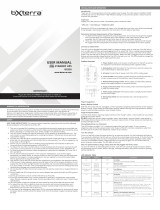
2. Slide the internal battery cartridges partially out of the UPS towards the front until their electri-
cal connection (A) may be disconnected.
3. Remove batteries from the UPS completely and dispose of them properly.
4. Examine the detailed connection diagram on the inside surface of the UPS system’s front panel.
5. Connect replacement batteries exactly according to the diagram, making sure that the input and
output cables (A) are connected as before, black to black and red to red. Reassemble the UPS by
reversing the steps above. Note: your new batteries should be allowed to charge for 2-4 hours
before they support a load.
A
200212046 93-2107 SmartPro 2U Owner’s Manual.qxd 1/6/2003 2:23 PM Page 12
  • Page 1 1
  • Page 2 2
  • Page 3 3
  • Page 4 4
  • Page 5 5
  • Page 6 6
  • Page 7 7
  • Page 8 8
  • Page 9 9
  • Page 10 10
  • Page 11 11
  • Page 12 12
  • Page 13 13
  • Page 14 14
  • Page 15 15
  • Page 16 16
  • Page 17 17
  • Page 18 18
  • Page 19 19
  • Page 20 20
  • Page 21 21
  • Page 22 22
  • Page 23 23
  • Page 24 24
  • Page 25 25
  • Page 26 26
  • Page 27 27
  • Page 28 28
  • Page 29 29
  • Page 30 30
  • Page 31 31
  • Page 32 32
  • Page 33 33
  • Page 34 34
  • Page 35 35
  • Page 36 36

Tripp Lite 1400VA Owner's manual

Category
Uninterruptible power supplies (UPSs)
Type
Owner's manual

Ask a question and I''ll find the answer in the document

Finding information in a document is now easier with AI