Florence 1570-8DBAF Installation guide

Type
Installation guide

This manual is also suitable for

www.orencemailboxes.com
Page 1 of 1691194 Rev G
INSTALLATION MANUAL
All Types - 1570 “F” Series
www.orencemailboxes.com
Page 2 of 16
91194 Rev G
TABLE OF CONTENTS
DESCRIPTION PAGE
GENERAL INFORMATION & ADVISORIES 2
PRODUCT INFORMATION 3
GET TO KNOW YOUR CBU 4
HARDWARE AND COMPONENTS 5
CONCRETE FOUNDATION PREPARATION 6
PEDESTAL INSTALLATION AND LEVELING 8
PEDESTAL TO CBU CABINET INSTALLATION 10
MASTER ACCESS DOOR ARROW LOCK INSTALLATION 12
PARCEL ARROW LOCK INSTALLATION 14
SECURITY TOOL - IMPORTANT NOTICE FOR USPS INSTALLERS 16
GENERAL INFORMATION AND ADVISORIES
CAUTION -- Transportation
• Lay boxes flat. Do not stand on end as box could fall over and cause injury.
• Cluster Box Units (CBU) are heavy. Use caution when lifting and carrying to avoid injury.
CAUTION -- Handling
• Use caution when lifting and carrying Cluster Box Units (CBU) to avoid injury.
• Pinch hazard exists when placing unit on foundation.
• Keep fingers and hands clear to avoid injury.
CAUTION -- Installation
• Cluster Box Units (CBU) are heavy. Do not stand CBU up without support to prevent tipping.
• Units may tip off unsecured anchors, possibly resulting in the CBU colliding with a person
and causing serious injury.
• CBU is also front-heavy when master load doors are open. Unit should be anchored or held
in place until secured to foundation. Installer should support unit or have assistance holding
the unit in place before opening the master load doors. Failure to do so could result in seri-
ous injury.
AT TENTION!
www.orencemailboxes.com
Page 3 of 1691194 Rev G
TYPE I TYPE II TYPE III TYPE IV TYPE V TYPE VI
INSTALLED HEIGHT
62 62 62 62 62 62
DEPTH
18 18 18 18 18 18
WIDTH
30 - 1/2” 30 - 1/2” 30 - 1/2” 30 - 1/2” 30 - 1/2” 30 - 1/2”
PEDESTAL HEIGHT
28 - 1/2” 28 - 1/2” 14 - 1/2” 14 - 1/2” 28 - 1/2” 14 - 1/2”
WEIGHT (WITHOUT PEDESTAL)*
107 LBS 111 LBS 147 LBS 137 LBS 112 LBS 148 LBS
WEIGHT (WITH PEDESTAL)*
125 LBS 129 LBS 162 LBS 152 LBS 130 LBS 163 LBS
QTY OF STANDARD COMPARTMENTS
8 12 16 13 4 8
STANDARD COMPARTMENT HEIGHT
3” 3” 3” 4-3/4” 6 - 1/2” 3”
QTY OF PARCEL COMPARTMENTS
2 1 2 1 2 4
PARCEL COMPARTMENT HEIGHT
10”, 13” 10 10”, 13” 10 10”, 13” 10”, 13”
* Weights do NOT include packaging - product only.
Note: For installation of Florence vogue
TM
decorative CBU accessories, please refer to manual located within the
vogue
TM
product packaging.
Florence vital
TM
cluster box units are
an officially licenced product of the
US Postal Service for centralized mail
delivery.
License #1CDSEQ-08-B-0012
1570-8 (TYPE I) 1570-12 (TYPE II) 1570-16 (TYPE III) 1570-13 (TYPE IV) 1570-4T5 (TYPE V)
1570-8T6 (TYPE VI)
CBU PRODUCT INFORMATION
vital™ cluster box units - 1570 Series
www.orencemailboxes.com
Page 4 of 16
91194 Rev G
GET TO KNOW YOUR FLORENCE CBU
vital™ cluster box unit - 1570 “F” Series
Before the assembly process begins, please review the illustration below. The major components that you
will be working with, and that are referred to in this instruction manual, are identified so as you are installing
your vital™ cluster box unit (CBU), you will be familiar with the terms that are used.
Cabinet
Pedestal
Rubber
Pad
Pedestal
Base
Pedestal
Column
Pedestal
Top Plate
Model 1570-16 shown for illustration purposes
www.orencemailboxes.com
Page 5 of 1691194 Rev G
HARDWARE AND COMPONENTS
vital
cluster box unit - 1570 “F” Series
NOTE: Anchors are not included with this product. Anchoring system selection coincides with type of
installation planned and should be purchased separately.
Outdoor Installation – anchoring systems for concrete pads are discussed in the next
section,
Concrete Foundation Preparation”.
The CBU cabinet and pedestal are packaged separately. Below is a list of components and hardware you
will receive in each package.
• Pedestal Package
• Template - guide to locate pedestal base anchors
• Rubber Pad - installed between ground and pedestal base
• Pedestal - fully assembled
• Cabinet Package
• CBU mailboxes and parcel lockers in protective cabinet
• Hardware kit in plastic bag (shipped inside unit compartment) that includes:
• Pedestal hardware
• Tenant keys
• Parcel keys and tags
• Installation manual
• Cleaning instructions
• Parcel door hardware (in plastic bag inside cabinet) - (2) McGard and (3) two-way screws;
(4) Arrow Lock nuts; and panel lock covers attached with temporary plastic fasteners.
www.orencemailboxes.com
Page 6 of 16
91194 Rev G
CONCRETE FOUNDATION PREPARATION
vital
cluster box unit - 1570 “F” Series
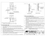
MATCH EXISTING GRADE IN PAVED AREAS
PEDESTAL
h* MIN.
(OPTIONAL-PLEASE SEE NEW CONCRETE NOTE
1
ON PAGE 7) COMPACT GRAVEL OR CRUSHED
STONE (OMIT WHERE SOLID ROCK OCCURS)
(OPTIONAL-PLEASE SEE NEW CONCRETE NOTE 1 ON PAGE 7
)
FIRM UNDISTURBED SOIL OR WELL-COMPACTED FILL
MOUNTING NUT / WASHER (NOT INCLUDED)
RUBBER PAD
REFER TO ANCHOR BOLTS RECOMMENDATIONS
ON PAGE 7, TABLE
2
10” TYP
4” TYP
4’’ MIN
TYP
BOX OUTLINE
w*
4’’ MIN
TYP
d*
2w*
2’-10TYP
(4) 1/2-13 ANCHOR
BOLTS; USE TEMPLATE
TO ALIGN PROPERLY
(TYPICAL)
4’’ MIN
TYP
4’’ MIN
TYP
*Pad recommendations for “h/d/w” outlined on page 7, Table 1
BOX OUTLINEBOX OUTLINE
www.orencemailboxes.com
Page 7 of 1691194 Rev G
NEW CONCRETE BASE:
1) Depending on climatic and soil conditions in the area of installation, optional foundation
material may be necessary as shown. Consult local building codes for recommendations.
2) Refer to Table 1 for thickness (h), width (w), and depth (d) of the concrete pad alternatives.
3) Concrete shall have a compressive strength of 3000 psi @ 28 days, contain 4% min ~ 6%
max air entrapment and be placed with a 3.50~4.50 slump in accordance to 301.
4) Use wire mesh as per (Standard) or fiber reinforced concrete as per (Standard).
EXISTING CONCRETE BASE:
1) Existing concrete pad must be at least 48” wide.
2) Concrete base and anchor bolts may be reused if:
a. existing ½” diameter expansion anchor bolts are firmly embedded in the concrete and
not damaged or corroded;
b. concrete foundation is not damaged; and
c. bolt hole pattern of the new unit matches the installed anchor bolts.
3) Additional considerations include:
a. if concrete is only 4” thick, then option ‘ b’ in Table 2 below cannot be used
b. any unused, existing anchor bolts must be cut flush to the level of the concrete surface
c. if concrete is damaged, replacement of foundation pad is required
CONCRETE FOUNDATION PREPARATION
vital
cluster box unit - 1570 “F” Series
TABLE 1: Pad Recommendations
h (Thickness) w (Width) min d (Depth) min
4” 47” 47”
5” 44” 44”
6” 42” 42”
7” 40” 40”
8” 39” 39”
TABLE 2
Expansion Anchor Bolt Recommendations
(or equivalent)
a. Hilti Kwik Bolt II (www.hilti.com)
- 1/2 inch diameter x 5 1/2 inches overall length
- Galvanized
- KB II 12-512, Stainless Steel
Minimum embedment in concrete must be at least
3 1/2 inches
b. ITW Ramset Redhead Turbolt (www.hilti.com)
- 1/2 inch diameter x 7 inches overall length
- Galvanized
Minimum embedment in concrete must be at least
4 1/8 inches
c. Rawl Stud (www.rawl.com)
- 1/2 inch diameter x 5 1/2 inches overall length
- Galvanized
Minimum embedment in concrete must be at least
4 inches
www.orencemailboxes.com
Page 8 of 16
91194 Rev G
PEDESTAL INSTALLATION AND LEVELING
vital
cluster box unit - 1570 “F” Series
In the event the concrete pad the CBU is being installed on is not level, the pedestal may be adjusted.
There are a number of leveling techniques used by construction professionals; however, the following
leveling method is being suggested as one alternative to consider.
If embedded anchors are not already in place in existing concrete, determine placement and location for
anchors. (See “Concrete Foundation Preparation” guide in previous section for anchor recommendations
and placement dimensions.)
• Tape pedestal base template to concrete in proper location(s).
• Drill holes through template to proper depth.
• Remove template and debris.
• Pound anchors in place.
1. Install Anchors (Skip if existing concrete and anchors are already in place)
• Place rubber pad over anchors onto concrete pad.
• Place pedestal over rubber pad and check if level.
• If leveling is required, shim pedestal with up to 3 washers on a given bolt.
• Washers, if required, should be placed between rubber pad and bottom of pedestal base.
• Check for level.
2. Use Pedestal to Check for Level
• Pedestal can now be installed according to anchoring hardware manufacturers instructions.
(Anchor hardware shown for illustration purposes - not included with unit. For anchoring system
information, please see “Concrete Foundation Preparation” section, page 7.)
• Continue to next section to install CBU cabinet to pedestal.
3. Install Pedestal to Concrete
PART # DESCRIPTION
9112 9 PEDESTAL FOR TYPE I, II, V
91121 PEDESTAL FOR TYPE III, IV, VI
91500 RUBBER PAD
REQUIRED TOOLS
REFER TO ANCHORING MFG INSTRUCTIONS
www.orencemailboxes.com
Page 9 of 1691194 Rev G
PEDESTAL INSTALLATION AND LEVELING
2
/
3.
www.orencemailboxes.com
Page 10 of 16
91194 Rev G
PART # DESCRIPTION
86089B 3/8-16 HEX NUT
86101 3/8-16 X 1.25 CARRIAGE BOLT
91079 FLOATING SHELF
9112 9 PEDESTAL FOR TYPE I, II, V
91121 PEDESTAL FOR TYPE III, IV, VI
86097 3/8” X .688 OD LOCK WASHER
REQUIRED TOOLS
9/16” SOCKET WRENCH
Open master loading doors until hold open arm engages.
Remove left and right side 91079 floating shelves, exposing mounting holes in base of unit.
Place unit on pedestal.
From underneath unit, insert four (4) 86101 carriage bolts upward.
From inside parcel compartments, add four (4) 86097 lock washers and tighten four (4)
86089B hex nuts. Torque to 22 foot-pounds.
Replace left and right side 91079 floating shelves.
Close master loading doors by first lifting slightly on the master hold open arm and then
shutting each door.
Installation of unit is now complete. Contact local USPS personnel to install Arrow Locks and
place unit into service.
PEDESTAL TO CBU CABINET INSTALLATION
vital
cluster box unit - 1570 “F” Series
1.
2.
3.
4.
5.
6.
7.
www.orencemailboxes.com
Page 11 of 1691194 Rev G
PEDESTAL TO CABINET INSTALLATION
Model 1570-16 shown for illustration purposes
1.
2/6.
4.
86101
91079
86089B
86097
3.
5.
7.
www.orencemailboxes.com
Page 12 of 16
91194 Rev G
PART # DESCRIPTION
86091 10-32 LOCK NUT
92300 ARROW LOCK SECURITY BRACKET
92303 LOCK SUPPORT PLATE
ARROW LOCK (USPS PROPRIETARY LOCK)
REQUIRED TOOLS
3/8” SOCKET WRENCH
MASTER ACCESS DOOR ARROW LOCK INSTALLATION
vital
cluster box unit - 1570 “F” Series
(to be completed by USPS personnel)
NOTE:
For USPS applications:
1) Arrow Lock is installed by US Postal Service personnel only. Contact your local Post Office to
arrange installation of Arrow Lock.
For Non-USPS applications:
1) Please disregard instructions related to Arrow Lock throughout this manual.
2) Master access door and parcel door private lock mechanisms will be installed at factory unless
otherwise specified by customer.
1.
2.
3.
4.
5.
6.
Open master access door.
Remove five (5) 86091 lock nuts, as well as 92303 lock support plate.
Dispose of plastic shipping spacers.
Place Arrow Lock into the Arrow Lock security bracket and position on door.
Replace one (1) 86091 lock nut in the rear position to secure Arrow Lock security
bracket.
Install 92303 lock support plate as shown.
Replace remaining four (4) 86091 lock nuts. Torque 25 to 30 inch-pounds
(overtightening may keep Arrow Lock from operating correctly).
www.orencemailboxes.com
Page 13 of 1691194 Rev G
MASTER ACCESS DOOR ARROW LOCK INSTALLATION
Model 1570-16 shown for illustration purposes
86091
ARROW LOCK
(If CBU is used for private delivery
purposes, please see the note on
pg 12 for Non-USPS application)
3/5.
92303
6.
4.
PLASTIC
SHIPPING
SPACER
2.
1.
86091
PLASTIC
SHIPPING
SPACER
86091
2.
ARROW LOCK
(If CBU is used for private delivery
purposes, please see the note on
pg 12 for Non-USPS application)
86091
4.
92303
6.
3/5.
www.orencemailboxes.com
Page 14 of 16
91194 Rev G
PARCEL ARROW LOCK INSTALLATION
vital
cluster box unit - 1570 “F” Series
(to be completed by USPS personnel)
PART # DESCRIPTION
84993 10-32 x .312 UNF-2A 18-8 SS
PASSIVATED MCGARD
84994 10-32 X .375 UNF-2A 18-8 SS
PASSIVATED 1-WAY TAMPER PROOF
86091 10-32 LOCK NUT
912 5 5 LATCHING ASSEMBLY COVER
912 5 9 ARROW LOCK COVER
ARROW LOCK (USPS PROPRIETARY LOCK)
Open parcel door, remove and discard four (4) plastic shipping retainers; two on latching
assembly cover and two on Arrow Lock cover.
Remove plastic bag of fasteners. All fasteners necessary to install postal lock are included in
one parcel door.
Install Arrow Lock as shown and secure with four (4) 86091 lock nuts. Torque
to 25 to 30 inch-pounds (overtightening may keep Arrow Lock from operating correctly).
Install latching assembly cover 91255 using two (2) 84994 fasteners.
Install Arrow Lock cover 91259 using two (2) 84993 McGard fasteners.
Remove label from cover. Repeat steps 1 - 6 for any additional parcel lockers within unit.
1.
2.
3.
4.
5.
6.
NOTE:
For USPS applications:
1) Arrow Lock is installed by US Postal Service personnel only. Contact your local Post Office to
arrange installation of Arrow Lock.
For Non-USPS applications:
1) Please disregard instructions related to Arrow Lock throughout this manual.
2) Master access door and parcel door private lock mechanisms will be installed at factory unless
otherwise specified by customer.
3) McGard fasteners and screwdriver not necessary for non-USPS (private delivery) applications.
REQUIRED TOOLS
FLAT SCREWDRIVER
USPS PROPRIETARY MCGARD TOOL
(See Page 16 for McGard procurement info.)
3/8” SOCKET WRENCH
PLIERS
www.orencemailboxes.com
Page 15 of 1691194 Rev G
PARCEL ARROW LOCK INSTALLATION
Model 1570-16 shown for illustration purposes
3.
4.
86091
91255
91259
84993
84994
5.
1/2.
6.
PLASTIC
SHIPPING
RETAINERS
1.
(If CBU is used for private delivery
purposes, please see the note on
pg 14 for Non-USPS application)
www.orencemailboxes.com
Page 16 of 16
91194 Rev G
IMPORTANT NOTICE FOR USPS INSTALLERS
USPS personnel must have a McGard screwdriver to install
and service the parcel Arrow Lock cover on the Florence vital
TM
cluster box unit.
(McGard Screwdrivers can be ordered by USPS personnel on the eBuy2 ordering system)
Note: Florence Manufacturing does not provide or sell the McGard Screwdriver
NOTE:
For USPS applications:
1) Arrow Lock is installed by US Postal Service personnel only. Contact your local Post Office to
arrange installation of Arrow Lock and place unit into service.
For Non-USPS applications:
1) Please disregard instructions related to Arrow Lock throughout this manual.
2) Master access door and parcel door private lock mechanisms will be installed at factory unless
otherwise specified by customer.
3) McGard fasteners and screwdriver not necessary for Non-USPS (private delivery) applications.
REPLACEMENT PARTS / MAINTENANCE
For a complete listing of all available replacement parts and/or maintenance procedures
for the vital™ 1570 series CBU by Florence, please refer to the vital™ Maintenance Manual
which may be downloaded from www.florencemailboxes.com/downloads.
Service parts are available for purchase through an Authorized Florence Dealer
and online at www.florencemailboxes.com/store.
Thank you for purchasing Florence products!
SECURITY TOOL REQUIREMENTS
  • Page 1 1
  • Page 2 2
  • Page 3 3
  • Page 4 4
  • Page 5 5
  • Page 6 6
  • Page 7 7
  • Page 8 8
  • Page 9 9
  • Page 10 10
  • Page 11 11
  • Page 12 12
  • Page 13 13
  • Page 14 14
  • Page 15 15
  • Page 16 16

Florence 1570-8DBAF Installation guide

Type
Installation guide
This manual is also suitable for

Ask a question and I''ll find the answer in the document

Finding information in a document is now easier with AI